Scholtes TI 8624 400 Operating Instructions Manual
- Categoria
- Fogões
- Tipo
- Operating Instructions Manual
Este manual também é adequado para

IT
Istruzioni per luso
PIANO COTTURA
Italiano, 1
IT
Français, 21
Deutsch, 41Nederlands, 31
English,11
GB FR
DENL
TI 8624
TI 8624 400
TI 7624
TI 7624 400
TI 6514
TI 6514 400
TI 6523
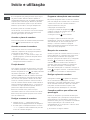
Sommario
Installazione, 2-4
Posizionamento
Collegamento elettrico
Descrizione dellapparecchio, 5
Pannello di controllo
Avvio e utilizzo, 6-7
Accensione del piano cottura
Accensione delle zone di cottura
Funzione booster
Spegnimento delle zone di cottura
Programmazione della durata di una cottura
Blocco dei comandi
Spegnimento del piano cottura
Consigli pratici per luso dellapparecchio
Dispositivi di sicurezza
Precauzioni e consigli, 8
Sicurezza generale
Smaltimento
Manutenzione e cura, 9
Escludere la corrente elettrica
Pulire lapparecchio
Smontare il piano
Descrizione tecnica dei modelli, 10
Português, 51
PT
Español, 61
ES

2
IT
È importante conservare questo libretto per poterlo
consultare in ogni momento. In caso di vendita, di
cessione o di trasloco, assicurarsi che resti insieme
allapparecchio per informare il nuovo proprietario sul
funzionamento e sui relativi avvertimenti.
Leggere attentamente le istruzioni: ci sono importanti
informazioni sullinstallazione, sulluso e sulla sicurezza.
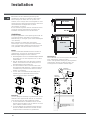
Posizionamento
Gli imballaggi non sono giocattoli per bambini e vanno
eliminati secondo le norme per la raccolta differenziata
(vedi Precauzioni e consigli).
Linstallazione va effettuata secondo queste istruzioni e
da personale professionalmente qualificato. Una errata
installazione può causare danni a persone, animali o cose.
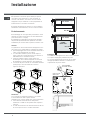
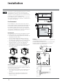
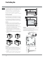
Incasso
Per garantire un buon funzionamento dellapparecchio è
necessario che il mobile abbia le caratteristiche adatte:
il piano dappoggio deve essere di materiale resistente al
calore, a una temperatura di circa 100°C;
se si desidera installare il piano cottura sopra un
forno, questo deve essere provvisto di un sistema di
raffreddamento a ventilazione forzata;
evitare di installare il piano cottura sopra una
lavastoviglie: alloccorrenza frapporre un elemento
di separazione a tenuta stagna fra i due apparecchi;
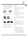
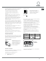
a seconda del piano cottura che si desidera installare
(vedi figure), il vano del mobile deve avere le
seguenti dimensioni:
Aerazione
Per consentire unadeguata aerazione e per evitare
il surriscaldamento delle superfici attorno
allapparecchio, il piano cottura deve essere posizionato:
a una distanza minima di 40 mm dalla parete
retrostante e di 600 mm da qualsiasi altra superficie
verticale;
in modo da mantenere una distanza minima di 20 mm
fra il vano per lincasso e il mobile sottostante.
5 mm
min. 20 mm
min. 20 mm
min. 40 mm
CASSETTO
5 mm
min. 40 mm
FORNO
VENTILATO
Fissaggio
Linstallazione dellapparecchio deve essere effettuata
su un piano dappoggio perfettamente piano.
Le eventuali deformazioni provocate da un errato
fissaggio potrebbero alterare le caratteristiche e
le prestazioni del piano cottura.
Installazione
560 +/- 1
490 +/- 1
48
590
520
560 +/- 1
490 +/- 1
48
574
504
690
520
560 +/- 1
490 +/- 1
48
785
750 +/- 1
510
490+/- 1
48
LATO ANTERIORE
DEL PIANO COTTURA
PIANO DI
APPOGGIO
30
40
PIANO COTTURA
ROVESCIATO

IT
3
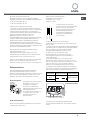
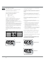
La lunghezza della vite di regolazione dei ganci
di fissaggio va impostata prima del loro montaggio,
in base allo spessore del piano dappoggio:
spessore di 30 mm: vite 23 mm;
spessore di 40 mm: vite 13 mm.
Per il fissaggio agire come segue:
1. Con le viti corte senza punta, avvitare le 4 molle di
centraggio nei fori posti al centro di ogni lato del piano;
2. inserire il piano cottura nel vano del mobile, centrarlo
ed esercitare una adeguata pressione sullintero
perimetro affinché il piano di cottura aderisca bene al
piano dappoggio.
3. per i piani con profili laterali: dopo aver inserito il
piano cottura nel mobile, inserire i 4 ganci di fissaggio
(ognuno con il suo perno) sul perimetro inferiore del
piano cottura, avvitandoli con le viti lunghe con punta
finché il vetro non aderisce al piano dappoggio.
È indispensabile che le viti delle molle di centraggio
rimangano accessibili.
In conformità alle norme di sicurezza, una volta
incassato lapparecchio, non debbono essere possibili
eventuali contatti con le parti elettriche.
Tutte le parti che assicurano la protezione debbono
essere fissate in modo tale da non poter essere tolte
senza laiuto di qualche utensile.
Collegamento elettrico
Lallacciamento elettrico del piano cottura e quello di
un eventuale forno da incasso devono essere realizzati
separatamente, sia per ragioni di sicurezza elettrica sia
per facilitare le operazioni di estrazione del forno.
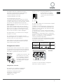
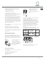
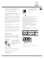
Morsettiera
Lapparecchio è provvisto, nella
parte inferiore, di una scatola
per il collegamento a differenti
tipi di alimentazione elettrica
(limmagine è indicativa e può
non corrispondere al modello
acquistato).
Collegamento monofase
Leventuale cavo in dotazione è predisposto
unicamente per questo tipo di installazioni.
Caratteristiche dellimpianto elettrico:
Tensione tipo e frequenza di rete
230/240V 1+N ~ 50 Hz
230V 2 ~ 50 Hz
Se il piano è dotato di cavo
di alimentazione già collegato,
allacciarlo alla rete rispettando
il colore dei fili come da schema
a fianco.
Se il piano non è dotato di cavo alimentazione collegato,
procedere come segue:
1. Utilizzare il cavo di alimentazione in dotazione (ove
presente) o un cavo di alimentazione appropriato, tipo
H05VV-F o di valore superiore, delle dimensioni adatte
(sezione cavo: 2,5 mm).
2. Servendosi di un cacciavite, far leva sulle linguette
del coperchio della morsettiera e aprirla (vedi immagine
Morsettiera).
3. La morsettiera è già predisposta per il collegamento
monofase: accertarsi che i cavallotti di collegamento tra i
morsetti 1 e 2 e quelli tra 4 e 5 siano in posizione
corretta (vedi immagine Monofase).
4. Posizionare i fili in accordo con il disegno e la tabella
che seguono ed effettuare il collegamento stringendo a
fondo tutte le viti dei morsetti.
Monofase
5. Fissare il cavo di alimentazione nellapposito
fermacavo e chiudere il coperchio.
PIANO COTTURA
ROVESCIATO
Blu
Marrone
N
Neutre
L
Phase
Verde / Giallo
Terre
LN
12345
5
FaseCavallotto Neutro Terra
1
2
3
4
Tensione tipo e
frequenza rete
Collegamenti elettrici Morsettiera
230/240V 1+N ~
50 Hz
Monofase
230V 2 ~ 50 Hz

4
IT
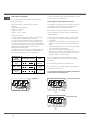
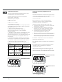
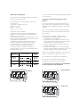
Altri tipi di collegamento
Leventuale cavo in dotazione non è utilizzabile per
questi tipi di installazione.
Se limpianto elettrico corrisponde a una delle seguenti
caratteristiche:
Tensione tipo e frequenza di rete
400V 2 - N ~ 50 Hz
230V 3 ~ 50 Hz
230V 2 + 2 - N ~ 50 Hz
procedere come segue:
1. Utilizzare un cavo di alimentazione appropriato, tipo
H05RR-F o di valore superiore, delle dimensioni adatte
(sezione cavo: 1,5 mm).
2. Servendosi di un cacciavite, far leva sulle linguette del
coperchio della morsettiera e aprirla (vedi immagine
Morsettiera).
3. Svitare la vite del serracavo e le viti dei morsetti
relativi al tipo di allaccio necessario e posizionare i
cavallotti di collegamento secondo la tabella e i disegni
che seguono.
4. Posizionare i fili in accordo con la tabella e i disegni
che seguono ed effettuare il collegamento stringendo a
fondo tutte le viti dei morsetti.
Bifase
5. Fissare il cavo di alimentazione nellapposito
fermacavo e chiudere il coperchio.
Allacciamento del cavo di alimentazione alla rete
In caso di collegamento diretto alla rete è necessario
interporre tra lapparecchio e la rete un interruttore
onnipolare con apertura minima fra i contatti di 3 mm.
Linstallatore è responsabile del corretto collegamento
elettrico e dellosservanza delle norme di sicurezza.
Prima di effettuare lallacciamento accertarsi che:
la presa abbia la messa a terra e sia a norma di
legge;
la presa sia in grado di sopportare il carico massimo
di potenza della macchina, indicato nella
targhetta caratteristiche posta sullapparecchio;
la tensione di alimentazione sia compresa nei valori
della targhetta caratteristiche;
la presa sia compatibile con la spina
dellapparecchio. In caso contrario sostituire la presa
o la spina; non usare prolunghe e multiple.
Ad apparecchio installato, il cavo elettrico e la presa
della corrente devono essere facilmente raggiungibili.
Il cavo non deve subire piegature o compressioni.
Il cavo deve essere controllato periodicamente e
sostituito solo da tecnici autorizzati.
Lazienda declina ogni responsabilità qualora
queste norme non vengano rispettate.
Trifase 400 2+N
Trifase 230
L1
L2
N2N1
12 34
5
L1 L2 L3
12345
L1 L2 N
12345
Fase Neutro TerraFase Neutro
5
1
2
3
4
5
Fase NeutroCavallotto Terra
1
2
3
4
Fase
5
Fase FaseCavallotto Terra
1
2
3
4
Fase
Tensione tipo e
frequenza rete
Collegamenti elettrici Morsettiera
400V 2-N ~
50 Hz
Trifase 400
2+N
230V 3 ~ 50 Hz Trifase 230
230V 2+2-N ~
50 Hz
Bifase

IT
5
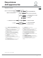
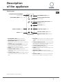
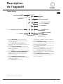
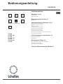
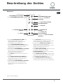
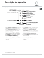
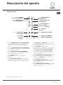
Display TIMER DI PROGRAMMAZIONE visualizza
le scelte relative alla programmazione (vedi Avvio e
utilizzo).
Tasti TIMER DI PROGRAMMAZIONE per regolare
la programmazione di ciascuna zona di cottura
(vedi Avvio e utilizzo).
Spie ZONA DI COTTURA PROGRAMMATA
indicano che la zona di cottura relativa è stata
programmata (vedi Avvio e utilizzo).
Tasto ON/OFF per accendere e spegnere
lapparecchio.
Tasto BLOCCO DEI COMANDI per impedire
modifiche fortuite alle regolazioni del piano cottura
(vedi Avvio e utilizzo).
Spia COMANDI BLOCCATI segnala lavvenuto
blocco dei comandi (vedi Avvio e utilizzo).
Tasto BOOSTER per accendere la
sovralimentazione - 3000 W - della zona di cottura
(vedi Avvio e utilizzo).
Spia
ZONA DI COTTURA SELEZIONATA indica
che la zona di cottura relativa è stata selezionata e
quindi sono possibili le varie regolazioni
Tasto SELEZIONE ZONA DI COTTURA per
selezionare la zona di cottura desiderata
Indicatore POTENZA segnala visivamente il livello
di calore raggiunto.
Tasto AUMENTO POTENZA per accendere la
piastra e regolare la potenza (vedi Avvio e utilizzo).
Tasto DIMINUZIONE POTENZA per regolare la
potenza e spegnere la piastra (vedi Avvio e
utilizzo).
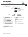
Pannello di controllo
Descrizione
dellapparecchio
15
0
00
5.
Tasto
AUMENTO POTENZA
Tasto
DIMINUZIONE POTENZA
Tasti
TIMER DI PROGRAMMAZIONE*
Spie
ZONA DI COTTURA PROGRAMMATA*
Display
TIMER DI PROGRAMMAZIONE*
Tasto
ON/OFF
Tasto
BLOCCO DEI COMANDI
Spia
COMANDI BLOCCATI
Indicatore
POTENZA
Tasto
BOOSTER*
Spia
ZONA DI COTTURA SELEZIONATA
Tasto SELEZIONE ZONA DI COTTURA
*
Presente solo in alcuni modelli.

6
IT
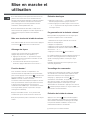
La colla applicata sulle guarnizioni lascia alcune
tracce di grasso sul vetro. Prima di utilizzare
lapparecchio, si raccomanda di eliminarle con un
prodotto specifico per la manutenzione non abrasivo.
Durante le prime ore di funzionamento è possibile
avvertire un odore di gomma, che comunque
scomparirà presto.
Quando il piano cottura viene collegato
elettricamente, dopo acuni secondi viene emesso un
breve segnale acustico. Soltanto a questo punto è
possibile accendere il piano cottura.
Accensione del piano cottura
Laccensione del piano cottura avviene tenendo
premuto il tasto
per circa un secondo.
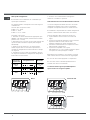
Accensione delle zone di cottura
Ciascuna zona di cottura viene azionata tramite il
dispositivo di regolazione della potenza composto da
due tasti (- e +).
Premere il tasto + per attivare la piastra, poi
impostare la potenza desiderata agendo sui tasti -
e +.
Per impostare direttamente la potenza massima,
premere brevemente il tasto -.
Funzione booster*
Per accelerare i tempi di riscaldamento, nelle zone di
cottura posteriori è possibile attivare la funzione
booster premendo il tasto
.Sul diaply indicatore
della potenza appare P. Questa funzione
sovralimenta a 3000 W la zona di cottura interessata.
Il booster si interrompe automaticamente dopo 4
minuti. Finché il booster di una delle zone di cottura
posteriori è attivo, la zona
di cottura anteriore relativa è limitata alla potenza
massima di 600 W (es: se è attivo il booster nella
piastra posteriore sinistra, si abbassa la potenza della
piastra anteriore sinistra).
Zone di cottura ovali*: possono essere sovralimentate
soltanto se è attivato lintero ovale.
Non mettere due pentole piccole sulle zone di cottura
ovali.
Spegnimento delle zone di cottura
Premere il tasto -: la potenza della zona di cottura
scende progressivamente, fino allo spegnimento.
Oppure premere contemporaneamente i tasti - e
+: la potenza torna immediatamente a 0 e la zona
di cottura si spegne.
Programmazione della durata
di una cottura*
È possibile programmare tutte le zone di cottura per
una durata compresa tra 1 e 99 minuti.
1. Selezionare la zona di cottura tramite il tasto di
selezione corrispondente.
2. Regolarne la temperatura.
3. Premere il tasto di programamzione
.
3. Impostare la durata di cottura desiderata tramite i
tasti - e +.
4. Confermare premendo il tasto
.
Il conto alla rovescia del timer ha inizio
immediatamente. La fine della cottura programmata è
indicata da un segnale acustico (per la durata di 1
minuto) e la zona di cottura si spegne.
Ripetere la procedura sopra descritta per ogni piastra
che si intende programmare.
Blocco dei comandi
Quando il piano cottura è in funzione, è possibile
bloccare i comandi per evitare il rischio di modifiche
fortuite alle regolazioni (bambini, operazioni di pulizia,
ecc.). Premendo il tasto
i comandi si bloccano e la
spia che si trova sopra al tasto si accende. Per
tornare ad agire sulle regolazioni (es. interrompere la
cottura) è necessario sbloccare i comandi: premere il
tasto
per qualche istante, la spia si spegne e i
comandi si sbloccano.
Spegnimento del piano cottura
Premendo il tasto lapparecchio si spegne.
Se i comandi dellapparecchio sono stati bloccati,
continueranno ad essere bloccati anche dopo aver
riacceso il piano di cottura. Per poter riaccendere il
piano è necessario prima sbloccare i comandi.
Avvio e utilizzo
*
Presente solo in alcuni modelli.

IT
7
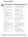
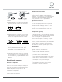
Consigli pratici per luso
dellapparecchio
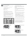
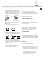
Adoperare recipienti di cottura il cui materiale di
fabbricazione sia compatibile con il principio
dellinduzione (materiale ferromagnetico). Si
raccomanda luso di pentole in: ghisa, acciaio
smaltato o inox speciale per induzione. Per sincerarsi
della compatibilità di un recipiente è sufficiente fare
una prova con una calamita.
Inoltre, per ottenere le migliori prestazioni dal piano di
cottura:
Adoperare pentole con fondo piatto e di elevato
spessore, per essere certi che aderiscano
perfettamente alla zona riscaldante.
Adoperare pentole di diametro sufficiente a coprire
completamente la zona riscaldante, in modo da
garantire lo sfruttamento di tutto il calore
disponibile.
Accertarsi che il fondo delle pentole sia sempre
perfettamente asciutto e pulito, per garantire la
corretta aderenza e una lunga durata, sia alle zone
di cottura che alle pentole stesse.
Evitare di utilizzare le stesse pentole utilizzate
sui bruciatori a gas: la concentrazione di calore sui
bruciatori a gas può deformare il fondo della
pentola, che perde aderenza.
Dispositivi di sicurezza
Rilevamento dei recipienti
Ciascuna zona di cottura è provvista di un dispositivo
di rilevamento della pentola. La piastra emette calore
unicamente in presenza di una pentola di dimensioni
adeguate alla zona di cottura stessa. La spia
lampeggiante può indicare:
una pentola incompatibile
una pentola di diametro insufficiente
il sollevamento della pentola
Indicatori di calore residuo
Finché la temperatura delle zone di cottura rimane
superiore a 60°C, anche dopo larresto gli indicatori di
calore residuo situati vicino alla zona di cottura
relativa restano accesi per prevenire il rischio di ustioni.
Surriscaldamento
In caso di surriscaldamento dei componenti
elettronici, il piano cottura si spegne automaticamente
e sul display appare . Questo messaggio
scompare e il piano torna utilizzabile non appena la
temperatura è scesa a un livello accettabile.
Interruttore di sicurezza
Lapparecchio è dotato di un interruttore di sicurezza
che spegne le zone di cottura automaticamente
quando viene raggiunto un tempo limite di utilizzo a
un dato livello di potenza. Durante linterruzione di
sicurezza, il display indica 0.
Esempio: la piastra posteriore destra è impostata su 5,
mentre la piastra anteriore sinistra su 2. La posteriore
destra si spegnerà dopo 3 ore di funzionamento, la
anteriore sinistra dopo 10 ore.
Segnale acustico
Alcune anomalie, quali:
un oggetto (pentola, posata, ecc.) posto per oltre
10 secondi sullarea dei comandi,
un versamento sullarea dei comandi,
una pressione esercitata a lungo su un tasto,
possono provocare lemissione di un segnale
acustico. Rimuovere la causa del
malfunzionamento per interrompere il segnale
acustico. In queste situazioni i comandi si bloccano
automaticamente: per sbloccarli premere il tasto
[icona chiave], le impostazioni vengono mantenute.
Se la causa dellanomalia non viene rimossa, il
segnale acustico persiste e il piano si spegne.
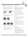
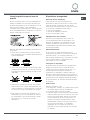
MATERIALE ADATTO MATERIALE NON ADATTO
Ghisa
Acciaio smaltato
Inox speciale
Rame,
Alluminio, Vetro, Terracotta,
Ceramica, Inox non magnetico

8
IT
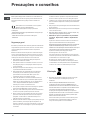
Precauzioni e consigli
Lapparecchio è stato progettato e costruito
in conformità alle norme internazionali di sicurezza.
Queste avvertenze sono fornite per ragioni di sicurezza
e devono essere lette attentamente.
Questa apparecchiatura è conforme alle
seguenti Direttive Comunitarie:
- 73/23/CEE del 19/02/73 (Bassa Tensione) e successive
modificazioni
- 89/336/CEE del 03/05/89 (Compatibilità
Elettromagnetica) e successive modificazioni
- 93/68/CEE del 22/07/93 e successive modificazioni.
- 2002/96/CE
Sicurezza generale
Controllare che la presa d'aria tramite la griglia del
ventilatore non sia mai ostruita. Il piano da incasso,
infatti, necessita di una corretta aerazione per il
raffreddamento dei componenti elettronici.
È sconsigliata l'installazione di un piano cottura a
induzione sopra un frigorifero sottotavolo (calore) o
sopra una lavatrice (vibrazioni). Lo spazio necessario
per la ventilazione degli elementi elettronici sarebbe
infatti insufficiente.
Lapparecchio è stato concepito per un uso di tipo
non professionale allinterno dellabitazione.
Lapparecchio non va installato allaperto, nemmeno
se lo spazio è riparato, perché è molto pericoloso
lasciarlo esposto a pioggia e temporali.
Non toccare la macchina a piedi nudi o con le mani
o i piedi bagnati o umidi.
Lapparecchio deve essere usato per cuocere
alimenti, solo da persone adulte e secondo le
istruzioni riportate in questo libretto. Non utilizzare
il piano come superficie di appoggio, né come
tagliere.
Il piano in vetroceramica è resistente agli urti
meccanici, tuttavia può incrinarsi (o eventualmente
frantumarsi) se colpito con un oggetto appuntito,
quale un utensile. In questi casi, scollegare
immediatamente lapparecchio dalla rete di
alimentazione e rivolgersi allAssistenza.
Se la superficie del piano è incrinata, spegnere
l'apparecchio per evitare la possibilità di scosse
elettriche.
Evitare che il cavo di alimentazione di altri
elettrodomestici entri in contatto con parti calde
del piano cottura.
Non dimenticare che la temperatura delle zone di
cottura rimane piuttosto elevata per almeno trenta
minuti dopo lo spegnimento. Il calore residuo è
segnalato anche da un indicatore (vedi Avvio e utilizzo).
Tenere a debita distanza dal piano cottura qualsiasi
oggetto che potrebbe fondere, ad esempio oggetti in
plastica, in alluminio o prodotti con un elevato
contenuto di zucchero. Fare particolare attenzione a
imballaggi e pellicole in plastica o alluminio:
se dimenticati sulle superfici ancora calde o tiepide
possono causare un grave danno al piano.
Assicurarsi che i manici delle pentole siano sempre
rivolti verso linterno del piano cottura per evitare che
vengano urtati accidentalmente.
Non staccare la spina dalla presa della corrente
tirando il cavo, bensì afferrando la spina.
Non fare pulizia o manutenzione senza aver prima
staccato la spina dalla rete elettrica.
Non posare oggetti metallici (coltelli, cucchiai,
coperchi, ecc.) sul piano perchè possono diventare
caldi.
Avvertenza per i portatori di pacemaker o altri
dispositivi medici impiantabili attivi:
Il piano cottura è conforme a tutte le normative vigenti
in materia di interferenze elettromagnetiche.
Questo prodotto è pertanto perfettamente rispondente
a tutti i requisiti di legge (direttive 89/336/CEE). È stato
progettato in modo da non creare inferenze ad altre
apparecchiature elettriche utilizzate, a condizione che
anche queste siano conformi alle suddette normative.
Il piano cottura a induzione genera campi
elettromagnetici a breve portata.
Per evitare ogni rischio di interferenze tra il piano di
cottura e il pacemaker, quest'ultimo dovrà essere
realizzato in conformità alle normative vigenti.
A tale riguardo, possiamo garantire unicamente la
conformità del nostro prodotto. Per informazioni sulla
conformità o eventuali problemi di incompatibilità, si
prega di rivolgersi al proprio medico curante o alla
casa produttrice del pacemaker.
Smaltimento
Smaltimento del materiale di imballaggio: attenersi
alle norme locali, così gli imballaggi potranno essere
riutilizzati.
La direttiva Europea 2002/96/CE sui rifiuti di
apparecchiature elettriche ed elettroniche (RAEE),
prevede che gli elettrodomestici non debbano essere
smaltiti nel normale flusso dei rifiuti solidi urbani. Gli
apparecchi dismessi devono essere raccolti
separatamente per ottimizzare il tasso di recupero e
riciclaggio dei materiali che li compongono ed
impedire potenziali danni per la salute e lambiente. Il
simbolo del cestino barrato è riportato su tutti i
prodotti per ricordare gli obblighi di raccolta separata.
Per ulteriori informazioni, sulla corretta dismissione
degli elettrodomestici, i detentori potranno rivolgersi al
servizio pubblico preposto o ai rivenditori.

IT
9
Manutenzione e cura
Escludere la corrente elettrica
Prima di ogni operazione isolare lapparecchio dalla
rete di alimentazione elettrica.
Pulire lapparecchio
Evitare luso di detergenti abrasivi o corrosivi, quali
i prodotti in bombolette spray per barbecue e forni,
smacchiatori e prodotti antiruggine, i detersivi in
polvere e le spugne con superficie abrasiva:
possono graffiare irrimediabilmente la superficie.
Non utilizzare mai pulitori a vapore o ad alta
pressione per la pulizia dellapparecchio.
Per una manutenzione ordinaria, è sufficiente
lavare il piano con una spugna umida,
asciugando quindi con una carta assorbente per
cucina.
Se il piano è particolarmente sporco, strofinare con
un prodotto specifico per la pulizia delle superfici in
vetroceramica, sciacquare e asciugare.
Per rimuovere gli accumuli di sporco più consistenti
servirsi dellapposito raschietto fornito in dotazione.
Intervenire non appena possibile, senza attendere
che lapparecchio si sia raffreddato, per evitare
lincrostazione dei residui. Eccellenti risultati si
possono ottenere usando una spugnetta in filo
dacciaio inossidabile - specifica per piani in
vetroceramica - imbevuta di acqua e sapone.
Il raschietto in dotazione è tagliente: utilizzarlo con
attenzione.
In caso sul piano cottura si fossero accidentalmente
fusi oggetti o materiali quali plastica o zucchero,
rimuoverli con il raschietto immediatamente, finché
la superficie è ancora calda.
Una volta pulito, il piano può essere trattato con
un prodotto specifico per la manutenzione e la
protezione: la pellicola invisibile lasciata da questo
prodotto protegge la superficie in caso di
scolamenti durante la cottura. Si raccomanda
di eseguire queste operazioni con lapparecchio
tiepido o freddo.
Ricordarsi sempre di risciacquare con acqua pulita
e asciugare accuratamente il piano: i residui di
prodotti potrebbero infatti incrostarsi durante la
successiva cottura.
Telaio in acciaio inox
(solo nei modelli con cornice)
Lacciaio inossidabile può macchiarsi per effetto
di unacqua molto calcarea lasciata per un periodo di
tempo prolungato a contatto dello stesso oppure a
causa di prodotti per la pulizia contenenti fosforo. Si
consiglia di sciacquare abbondantemente e
asciugare con cura dopo la pulizia del piano. In caso
di versamenti dacqua, intervenire rapidamente
asciugando con cura.
Smontare il piano
Nel caso si renda necessario smontare il piano
cottura:
1. togliere le viti che fissano le molle di centraggio sui lati;
2. allentare le viti dei ganci di fissaggio sugli angoli;
3. estrarre il piano cottura dal vano del mobile.
Raccomandiamo di evitare di accedere ai
meccanismi interni per tentare una riparazione.
In caso di guasto, contattare lAssistenza.

10
IT
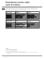
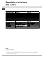
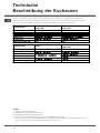
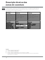
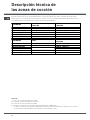
Descrizione tecnica delle
zone di cottura
Il sistema a induzione è il procedimento di cottura più rapido che esista. A differenza delle piastre tradizionali,
non è la zona di cottura che si riscalda: il calore viene generato direttamente allinterno della pentola, la quale
dovrà possedere necessariamente un fondo in materiale ferromagnetico.
Legenda:
I = zona di cottura a induzione semplice
IO= zona di cottura a induzione ovale
ID = zona di cottura a induzione doppia
B = booster: la zona di cottura può essere sovralimentata a 3000 W
* = la potenza massima è limitata a 600 W finché è attivo il booster nella zona di cottura posteriore relativa (vedi
Avvio e utilizzo).
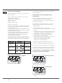
PIANI COTTURA
TI 8624
TI 8624 400
TI 7624
TI 7624 400
Zone di cottura Potenza Potenza
Posteriore destro IO 1200/2400 W B 3000 W ID 2400 W B 3000 W
Anteriore destro I 1200 W 600 W se* I 1200 W 600 W se*
Anteriore sinistro ID 2400 W B 3000 W IO 1200/2400 W B 3000 W
Posteriore sinistro I 1200 W 600 W se* I 1200 W 600 W se *
Potenza max totale 7200 7200
PIANI COTTURA TI 6523
TI 6514
TI 6514 400
Zone di cottura Potenza Potenza
Posteriore destro I 1200 W 600 W se* ID 1800 W B 3000 W
Anteriore destro I 1200 W 600 W se*
Anteriore sinistro
IO 1200/2400 W B 3000 W
I 1800 W
Posteriore sinistro ID 1800 W B 3000 W I 1200 W
Potenza max totale 6600 W 6600 W

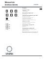
GB
Operating Instructions
HOB
English,11
GB
TI 8624
TI 8624 400
TI 7624
TI 7624 400
TI 6514
TI 6514 400
TI 6523
Contents
Installation, 12-14
Positioning
Electrical connections
Description of the appliance, 15
Control panel
Start-up and use, 16-17
Switching on the hob
Switching on the cooking zones
Booster function
Switching off the cooking zones
Programming the cooking time
Control panel lock
Spegnimento del piano cottura
Practical advice on using the appliance
Safety devices
Precautions and tips, 18
General safety
Disposal
Maintenance and care, 19
Switching the appliance off
Cleaning the appliance
Removing the hob
Technical description of models, 20
Italiano, 1
Français, 21
Deutsch, 41Nederlands, 31
FR
DENL
IT
Português, 51
PT
Español, 61
ES

12
GB
Before operating your new appliance please read this
instruction booklet carefully. It contains important
information for safe use, installation and care of the
appliance.
Please keep these operating instructions for future
reference. Pass them on to possible new owners of the
appliance.
Positioning
Keep packaging material out of the reach of children. It
can become a choking or suffocation hazard (see
Precautions and tips).
The appliance must be installed by a qualified person
according to the instructions provided. Incorrect
installation may damage property or cause harm to
people or animals.
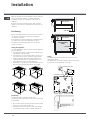
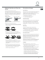
Fitting the appliance
Use the appropriate cabinet to ensure that the appliance
functions properly.
The supporting surface must be heat-resistant up to a
temperature of around 100°C
if the appliance is to be installed above an oven, the
oven must have a forced ventilation cooling system
avoid installing the hob above a dishwasher: if this
cannot be avoided, place a separation device at a
static distance between the two appliances
depending on the hob you want to install the cabinet
must have the following dimensions (see figure):
Ventilation
To allow adequate ventilation and to avoid
overheating of the surrounding surfaces the hob should
be positioned:
At a minimum of 40 mm from the back panel and 600
mm from any other vertical surfaces.
maintaining a minimum distance of 20 mm between
the installation cavity and the cabinet underneath.
5 mm
min. 20 mm
min. 20 mm
min. 40 mm
COMPARTMENT
5 mm
min. 40 mm
FAN-ASSISTED
OVEN
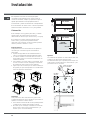
Fixing
The appliance must be installed on a perfectly level
supporting surface.
Any deformities caused by improper fixing could change
the features and the operation of the hob.
Installation
560 +/- 1
490 +/- 1
48
590
520
560 +/- 1
490 +/- 1
48
574
504
690
520
560 +/- 1
490 +/- 1
48
785
750 +/- 1
510
490+/- 1
48
FRONT SIDE OF HOB
30
40
SUPPORTING
SURFACE
UNDERSIDE OF HOB
h Wortop

GB
13
If the hob has a supply cable fitted,
connect it to the mains, using the
colours as a guide (see diagram).
If the hob does not have a supply cable fitted, proceed
as follows:
1. Use the supply cable provided (where applicable) or
a suitable supply cable, H05VV-F or higher, with the right
dimensions (cable section: 2.5 mm).
2. To open the terminal board, insert a screwdriver into
the side tabs of the cover (see Terminal board picture).
3. The terminal board is designed for single-phase
connection: make sure the connection supports between
springs 1 and 2 and those between 4 and 5 are in the
right position (see Single-phase picture).
4. Position the wires according to the following diagram
and table and connect the appliance by tightening all
the screws for the springs as much as possible.
Single-phase
5. Secure the power supply cable by fastening the
clamp screw then put the cover back on.
The thickness of the supporting surface should be taken
into account when choosing screws for the fixing hooks:
thickness of 30 mm: 23 mm screws
thickness of 40 mm: 13 mm screws
Fix the appliance as follows:
1. Use short flat-bottomed screws to fix the 4 alignment
springs in the holes provided in the centre of each side
of the hob.
2. Insert the hob in the cavity, make sure it is in a central
position and push down on the whole perimeter until the
hob is stuck to the supporting surface.
3. for hobs with raised sides: after inserting the hob into
its cavity, insert the 4 fixing hooks (each has its own pin)
into the lower edges of the hob, using the long pointed
screws to fix it in place, until the glass is stuck to the
supporting surface.
The screws for the alignment springs must remain
accessible.
In order to adhere to safety standards, the appliance
must not come into contact with electrical parts once it
has been installed.
All parts that ensure the safe operation of the appliance
must not be removable without the aid of a tool.
Electrical connection
The electrical connection of the hob and any built-in
oven must be carried out separately, both for safety
purposes and to make extracting the oven easier.
Terminal board
On the lower part of the
appliance there is a connection
box for the different types of
electricity supply (the picture is
only an indication and is not an
exact representation of the
purchased model).
Single-phase connection
The cable provided should only be used for this type of
installation.
Mains supply characteristics:
Voltage and mains frequency
230/240V 1+N ~ 50 Hz
230V 2 ~ 50 Hz
UNDERSIDE OF HOB
5
1
2
3
4
U-bolt
connection support
Phase Neutral Earth
Blue
Brown
N
Neutral
L
Live
Green/Yellow
Earth
Voltage and
mains
frequency
Electrical connections
Terminal
board
230/240V 1+N ~
50 Hz
230V 2 ~ 50 Hz
Single-
phase
LN
12345

14
GB
Other types of connection
The cable provided is not suitable for the following
types of installation.
If the mains supply corresponds with one of the
following:
Voltage and mains frequency
400V 2 - N ~ 50 Hz
230V 3 ~ 50 Hz
230V 2 + 2 - N ~ 50 Hz
proceed as follows:
1. Use a suitable supply cable, H05RR-F or higher, with
the right dimensions (cable section: 1.5 mm).
2. To open the terminal board, insert a screwdriver into
the side tabs of the cover (see Terminal board picture).
3. Loosen the cable clamp screw and the terminal board
screws according to the type of connection required and
position the connection supports as shown in the
following table and diagrams.
4. Position the wires according to the following table and
diagrams and connect the appliance by tightening all
the screws for the springs as much as possible.
Two-phase
5. Secure the power supply cable by fastening the clamp
screw then put the cover back on.
Connecting the supply cable to the mains
If the appliance is being connected directly to the mains
an omnipolar circuit-breaker must be installed with a
minimum opening of 3 mm between contacts.
The installer must ensure that the correct electrical
connection has been made and that it is compliant with
safety regulations.
Before connecting to the power supply, make sure that:
The appliance is earthed and the plug is compliant
with the law.
The socket can withstand the maximum power of the
appliance, which is indicated on the attached data
plate.
The power supply voltage is in the range between the
values indicated on the data plate.
The socket is compatible with the plug of the
appliance. If the socket is incompatible with the plug,
ask an authorised technician to replace it. Do not use
extension cords or multiple sockets.
Once the appliance has been installed, the power
supply cable and the electrical socket must be easily
accessible.
The cable must not be bent or compressed.
The cable must be checked regularly and replaced by
authorised technicians only.
The manufacturer declines any liability should these
safety measures not be observed.
Three-phase 400 2+N
Three-phase 230
Phase Neutral EarthPhase Neutral
5
1
2
3
4
5
1
2
3
4
U-bolt
connection
support
PhasePhase Neutral Earth
5
1
2
3
4
U-bolt
connection
support
Phase PhasePhase Earth
Voltage and
mains
frequency
Electrical connections
Terminal
board
400V 2-N ~
50 Hz
Three-phase
400 2+N
230V 3 ~ 50 Hz
Three-phase
230
230V 2+2-N ~
50 Hz
Two-phase
L1
L2
N2N1
12 34
5
L1 L2 L3
12345
L1 L2 N
12345

GB
15
PROGRAMME TIMER display shows the
programme chosen (see Start-up and use).
PROGRAMME TIMER button controls the
programmes for each cooking zone (see Start-up
and use).
COOKING ZONE PROGRAMMED indicator light
shows that a particular cooking zone has been
programmed (see Start-up and use).
ON/OFF button switches the appliance on and off.
CONTROL PANEL LOCK button prevents
accidental changes to the hob settings (see Start-
up and use).
CONTROL PANEL LOCK indicator light shows the
control panel has been locked (see Start-up and
use).
BOOSTER button switches on the booster function
- 3000W - of the cooking zone (see Start-up and
use).
COOKING ZONE SELECTED
indicator light shows
that a particular cooking zone has been selected
and so various controls may be used.
COOKING ZONE SELECTOR
button can be used
to select the required cooking zone.
POWER indicator provides a visual display for the
current heat level.
INCREASE POWER button switches on the
hotplate and controls the power (see Start-up and
use).
REDUCE POWER button controls the power and
switches off the hotplate (see Start-up and use).
Control panel
Description
of the appliance
15
0
00
5.
INCREASE POWER
button
REDUCE POWER
button
PROGRAMME TIMER
button*
COOKING ZONE PROGRAMMED
indicator light*
PROGRAMME TIMER
display*
ON/OFF
button
CONTROL PANEL LOCK
button
CONTROL PANEL LOCK
indicator
light
POWER
indicator
BOOSTER
button*
COOKING ZONE SELECTED
indicator light
COOKING ZONE SELECTOR button
*
Only available on certain models.

16
GB
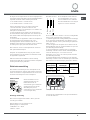
The glue applied on the gaskets leaves traces of
grease on the glass. Before using the appliance, we
recommend you remove these with a special non-
abrasive cleaning product. During the first few hours
of use there may be a smell of rubber which will
disappear very quickly.
A few seconds after the hob is connected to the
electricity supply, a buzzer will sound. The hob may
now be switched on.
Switching on the hob
To switch the hob on, press and hold the button
for about a second.
Switching on the cooking zones
Each cooking zone is controlled by a device
consisting of two buttons (- and +).
Press the + button to activate the hotplate, then
set the power to the level required using the - and
+ buttons.
To set the power to maximum, hold down the -
button briefly.
Booster function*
The booster function for the rear cooking zones may
be used to shorten heating-up times. It is activated by
pressing the
button. P appears on the power
indicator display. This function boosts the power of
the relevant zone to 3000W.
It stops automatically after 4 minutes. Until the booster
of one of the rear zones is activated, the front zones
have a maximum power of 600 W (e.g. if the left rear
hotplate booster is activated, the power of the left front
hotplate decreases).
Oval cooking zones*: may be used with the booster
only if the whole oval is activated.
Do not put two small pans on the oval cooking
zones.
Switching off the cooking zones
Press the -button: the power of the cooking zone
will progressively decrease until it is switched off.
Alternatively, the - and + buttons may be
pressed simultaneously. This immediately returns
the power setting to 0 and the cooking zone
switches off.
Programming the cooking duration*
All the cooking zones may be programmed for a
length of time between 1 and 99 minutes.
1. Select the cooking zone with the corresponding
button.
2. Set the temperature.
3. Press the
button.
3. Set the cooking time using the - and + buttons.
4. Confirm the settings by pressing the
button.
The timer begins counting down immediately. A buzzer
sounds for about 1 minute and the cooking zone switches
off when the set programme has finished.
Repeat the above procedure for each hotplate you
wish to programme.
Control panel lock
When the hob is switched on, it is possible to lock the
oven controls to avoid accidental changes to the
settings (by children, during cleaning, etc.). Press the
button to lock the control panel and the indicator
light above the button will be lit. To use any of the
controls (e.g. to stop cooking), you must switch off
this function: press the
button for a few moments,
the indicator light will switch off and the lock function
is removed.
Switching off the hob
Press the button to switch the appliance off.
If the control panel lock is on, the controls will
continue to be locked even after the hob is switched
on again. In order to switch the hob on again, you
must first remove the lock function.
Start-up and use
*
Only available on certain models.

GB
17
Practical advice on using the appliance
Use cookware made from materials that are
compatible with the induction principle (ferromagnetic
material). We especially recommend pans made from:
cast iron, coated steel or special stainless steel
adapted for induction. Us ea magnet to test the
compatibility of the cookware.
In addition, to obtain the best results from your hob:
Use pans with a thick, flat base to fully utilise the
cooking zone.
Always use pans with a diameter that is large
enough to cover the hotplate fully, in order to use all
the available heat.
Make sure that the base of the cookware is always
dry and clean, to fully utilise and extend the life of
both the cooking zones and cookware.
Avoid using the same cookware that has been used
on gas burners: the heat concentration on gas
burners may deform the base of the pan, causing it
not to fit correctly.
Safety devices
Pan sensor
Each cooking zone is fitted with a pan sensor device.
The hotplate only emits heat when a pan with suitable
measurements for the cooking zone is placed on it. If
the indicator light is flashing, it may indicate:
an incompatible pan
a pan that is too small
the pan has been taken away
Residual heat indicators
While the temperature of the cooking zone remains
above 60°C, even after the programme has finished,
the residual heat indicators placed near the relevant
cooking zone remain lit to prevent the risk of burns.
Overheating protection
If the electronic elements overheat, the hob switches
off automatically and appears on the display.
When the temperature has reached an appropriate
level, this message disappears and the hob may be
used again.
Safety switch
The appliance has a safety switch that automatically
switches off the cooking zones when they have been
in operation for a certain amount of time at a given
power level. When the safety switch has been
triggered, the display shows 0.
For example: the right rear hotplate is set to 5 and will
switch off after 3 hours of continuous operation, while
the front left hotplate is set to 2 and will switch off after
10 hours.
Buzzer
This can indicate several irregularities:
an object (a pan, cutlery, etc.) has been placed on
the control panel for more than 10 seconds
something has been spilt on the control panel
a button has been pressed for too long
All the above can cause the buzzer to sound.
Remove the cause of the malfunction to stop the
buzzer. The control panel locks automatically in
these situations: to unlock it press the button [key
icon], the settings will have been maintained. If the
cause of the problem is not removed, the buzzer will
keep sounding and the hob will switch off.
*
SUITABLE
UNSUITABLE
Cast iron
Enamelled steel
Special stainless steel
Copper,
Aluminium, Glass, Earthenware,
Ceramic, non magnetic Stainless steel

18
GB
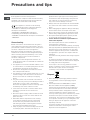
This appliance has been designed and
manufactured in compliance with international safety
standards. The following warnings are provided for
safety reasons and must be read carefully.
This appliance conforms to the following
European Economic Community directives:
- 73/23/EEC of 19/02/73 (Low Voltage) and
subsequent amendments
- 89/336/EEC of 03/05/89 (Electromagnetic
Compatibility) and subsequent amendments
- 93/68/EEC of 22/07/93 and subsequent amendments
- 2002/96/EC
General safety
Make sure that the air inlet behind the fan grille is
never obstructed. The built-in hob should, in fact, be
provided with suitable ventilation for the cooling of the
electronic components used in the appliance.
We advise against the installation of an induction
hob above an under-the-counter refrigerator (heat) or
above a washing machine (vibrations). In fact, there
would be insufficient space for the ventilation of
electronic components.
This appliance was designed for domestic use
inside the home and is not intended for commercial
or industrial use.
The appliance must not be installed outdoors, even
in covered areas. It is extremely dangerous to leave
the appliance exposed to rain and storms.
Do not touch the appliance with bare feet or with
wet or damp hands and feet.
The appliance must be used by adults only, to cook
food according to the instructions in this manual.
Do not use the hob as a worktop or chopping
board.
The glass ceramic hob is resistant to mechanical
shocks, but it may crack (or even break) if hit with a
sharp object such as a tool. If this happens,
disconnect the appliance from the electricity mains
immediately and contact a Service Centre.
If the surface of the hob is cracked, switch off the
appliance to prevent electric shocks from
occurring.
Ensure that power supply cables of other electrical
appliances do not come into contact with the hot
parts of the hob.
Remember that the temperature of the cooking
zones remains relatively high for at least thirty
minutes after they have been switched off. An
indicator light provides a warning when residual
heat is present (see Start-up and use).
Keep any object that could melt away from the hob,
for example plastic and aluminium objects, or
Precautions and tips
products with a high sugar content. Keep plastic
and aluminium film and packaging away from the
hob: if placed on surfaces that are still hot, they
may cause serious damage to the hob.
Always make sure pan handles are turned towards
the centre of the hob in order to avoid accidental
burns.
When unplugging the appliance always pull the plug
from the mains socket, do not pull on the cable.
Never carry out any cleaning or maintenance work
without having unplugged the plug from the mains.
Do not place metal objects (knives, spoons, pan lids,
etc.) on the hob as they may become hot.
For the attention of wearers of pacemakers or
other active implants:
The hob complies with all current standards on
electromagnetic interference.
Your induction hob is therefore perfectly in keeping
with legal requirements (89/336/CEE directives). It is
designed not to create interference on any other
electrical apparatus being used on condition that
the apparatus in question also complies with this
legislation.
Your induction hob generates short-range magnetic
fields.
To avoid any interference between your induction
hob and a pacemaker, the latter must be designed
to comply with relevant regulations.
In this respect, we can only guarantee our own
product conformity. Please consult the pacemaker
manufacturer or your doctor concerning its
conformity or any possible incompatibility.
Disposal
When disposing of packaging material: observe
local legislation so that the packaging may be
reused.
The European Directive 2002/96/EC on Waste
Electrical and Electronic Equipment (WEEE),
requires that old household electrical appliances
must not be disposed of in the normal unsorted
municipal waste stream. Old appliances must be
collected separately in order to optimise the
recovery and recycling of the materials they contain
and reduce the impact on human health and the
environment. The crossed out wheeled bin symbol
on the product reminds you of your obligation, that
when you dispose of the appliance it must be
separately collected.
Consumers should contact their local authority or
retailer for information concerning the correct
disposal of their old appliance.

GB
19
Maintenance and care
Switching the appliance off
Disconnect your appliance from the electricity supply
before carrying out any work on it.
Cleaning the appliance
Do not use abrasive or corrosive detergents (for
example, spray cans for cleaning barbecues and
ovens), stain removers, anti-rust products, powder
detergents or sponges with abrasive surfaces: these
may scratch the surface.
Never use steam cleaners or pressure cleaners on
the appliance.
It is usually enough to wash the hob with a damp
sponge and dry it with absorbent kitchen roll.
If the hob is particularly dirty, rub with a special
glass ceramic cleaning product, rinse and dry.
To remove more stubborn dirt, use the scraper
provided. Remove spills as soon as possible,
without waiting for the appliance to cool, to avoid
residues forming crusty deposits. You can obtain
excellent results by using a rust-proof steel wire
sponge - specifically designed for glass ceramic
surfaces - soaked in soapy water.
The scraper provided is sharp: be careful when
using it.
If plastic or sugary substances are accidentally
melted on the hob, remove them immediately with
the scraper, while the surface is still hot.
Once it is clean, the hob may be treated with a
special maintenance and protection product: the
invisible film left by this product protects the
surface from drips during cooking. This should be
done while the appliance is warm or cold.
Always remember to rinse the appliance with clean
water and dry the hob thoroughly: residues can
become encrusted during cooking.
Stainless steel frame (only for models with outer
frame)
Rust-proof steel can be marked by hard water that has
been left on the surface for a long time, or by cleaning
products containing phosphorus. After cleaning, it is
advisable to rinse the surface well and dry it
thoroughly. If water is spilt on the surface, dry it
quickly and thoroughly.
Removing the hob
If it is necessary to remove the hob:
1. loosen the screws fixing the alignment springs on
each side
2. loosen the screws holding the fixing hooks in each
corner
3. take the hob out of its installation cavity
Do not attempt to repair the appliance yourself.
If the appliance breaks down, contact a Service
Centre.

20
GB
Technical description of
cooking zones
The induction system is the quickest existing way of cooking. Unlike traditional hotplates where the cooking zone
heats up, with the induction system heat is generated directly inside ferromagnetic based pans.
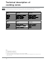
Key:
I = single induction cooking zone
OI= oval induction cooking zone
DI = double induction cooking zone
B = booster: the power of the cooking zone may be boosted to 3000W
* = the maximum power is limited to 600 W until the booster is activated for the appropriate rear cooking zone (see
Start-up and use).
HOBS
TI 8624
TI 8624 400
TI 7624
TI 7624 400
Cooking zones Wattage Wattage
Back right IO 1200/2400 W B 3000 W ID 2400 W B 3000 W
Front right I 1200 W 600 W se* I 1200 W 600 W se*
Front left ID 2400 W B 3000 W IO 1200/2400 W B 3000 W
Back left I 1200 W 600 W se* I 1200 W 600 W se *
Maximium total wattage 7200 7200
HOBS TI 6523
TI 6514
TI 6514 400
Cooking zones Wattage Wattage
Back right I 1200 W 600 W se* ID 1800 W B 3000 W
Front right I 1200 W 600 W se*
Front left
IO 1200/2400 W B 3000 W
I 1800 W
Back left ID 1800 W B 3000 W I 1200 W
Maximium total wattage 6600 W 6600 W
A página está carregando...
A página está carregando...
A página está carregando...
A página está carregando...
A página está carregando...
A página está carregando...
A página está carregando...
A página está carregando...
A página está carregando...
A página está carregando...
A página está carregando...
A página está carregando...
A página está carregando...
A página está carregando...
A página está carregando...
A página está carregando...
A página está carregando...
A página está carregando...
A página está carregando...
A página está carregando...
A página está carregando...
A página está carregando...
A página está carregando...
A página está carregando...
A página está carregando...
A página está carregando...
A página está carregando...
A página está carregando...
A página está carregando...
A página está carregando...
A página está carregando...
A página está carregando...
A página está carregando...
A página está carregando...
A página está carregando...
A página está carregando...
A página está carregando...
A página está carregando...
A página está carregando...
A página está carregando...
A página está carregando...
A página está carregando...
A página está carregando...
A página está carregando...
A página está carregando...
A página está carregando...
A página está carregando...
A página está carregando...
A página está carregando...
A página está carregando...
A página está carregando...
A página está carregando...
-
 1
1
-
 2
2
-
 3
3
-
 4
4
-
 5
5
-
 6
6
-
 7
7
-
 8
8
-
 9
9
-
 10
10
-
 11
11
-
 12
12
-
 13
13
-
 14
14
-
 15
15
-
 16
16
-
 17
17
-
 18
18
-
 19
19
-
 20
20
-
 21
21
-
 22
22
-
 23
23
-
 24
24
-
 25
25
-
 26
26
-
 27
27
-
 28
28
-
 29
29
-
 30
30
-
 31
31
-
 32
32
-
 33
33
-
 34
34
-
 35
35
-
 36
36
-
 37
37
-
 38
38
-
 39
39
-
 40
40
-
 41
41
-
 42
42
-
 43
43
-
 44
44
-
 45
45
-
 46
46
-
 47
47
-
 48
48
-
 49
49
-
 50
50
-
 51
51
-
 52
52
-
 53
53
-
 54
54
-
 55
55
-
 56
56
-
 57
57
-
 58
58
-
 59
59
-
 60
60
-
 61
61
-
 62
62
-
 63
63
-
 64
64
-
 65
65
-
 66
66
-
 67
67
-
 68
68
-
 69
69
-
 70
70
-
 71
71
-
 72
72


Scholtes TI 8624 400 Operating Instructions Manual
- Categoria
- Fogões
- Tipo
- Operating Instructions Manual
- Este manual também é adequado para
em outras línguas
- español: Scholtes TI 8624 400
- français: Scholtes TI 8624 400
- italiano: Scholtes TI 8624 400
- English: Scholtes TI 8624 400
- Nederlands: Scholtes TI 8624 400
- Deutsch: Scholtes TI 8624 400
Artigos relacionados
Outros documentos
-
Whirlpool TT 6013 T (NR) Guia de usuario
-
-
-
Indesit TK 63 T BI Manual do proprietário
-
Whirlpool TK 63 T BI Manual do proprietário
-
-
-
Whirlpool KBT 6412 I IX/HA Guia de usuario
-
-
Indesit KBT 6124 ID IX Manual do proprietário