
Motors | Automation | Energy | Transmission & Distribution | Coatings
Frequency Inverter
Convertidor de Frecuencia
Inversor de Frequência
CFW100 V3.1X
Quick Reference of Parameters, Alarms and Faults
Referencia Rápida de los Parámetros, Alarmas y Fallas
Referência Rápida dos Parâmetros, Alarmes e Falhas


Quick Reference of Parameters, Alarms and Faults
Series: CFW100
Language: English
Document: 10006259370 / 01
Software version: 3.1X
Build 1180
Publication Date: 04/2019

SUMMARY OF REVISIONS
Version Revision Description
3.0X R00 First edition.
3.1X R01
General Revision.

English
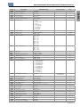
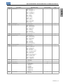
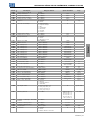
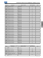
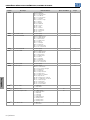
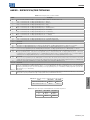
QUICK REFERENCE OF PARAMETERS, ALARMS AND FAULTS
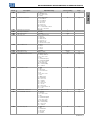
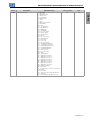
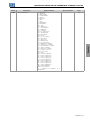
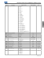
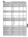
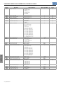
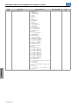
Param. Description Adjustable Range Factory Setting Prop.
P000 Access to Parameters 0 to 9999 1
P001 Speed Reference 0 to 9999 ro
P002 Output Speed (Motor) 0 to 9999 ro
P003 Motor Current 0.0 to 10.0 A ro
P004 DC Link Voltage 0 to 524 V ro
P005 Output Frequency (Motor) 0.0 to 400.0 Hz ro
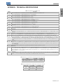
P006 Inverter Status 0 = Ready
1 = Run
2 = Undervoltage
3 = Fault
4 = Self-Tuning
5 = Configuration
6 = DC Braking
7 = Reserved
8 = Fire Mode
ro
P007 Output Voltage 0 to 240 V ro
P009 Motor Torque -200.0 to 200.0 % ro, VVW
P011 Power Factor 0.00 to 1.00 ro
P012 DI8 to DI1 Status 0 to FF (hexa)
Bit 0 = DI1
Bit 1 = DI2
Bit 2 = DI3
Bit 3 = DI4
Bit 4 = DI5
Bit 5 = DI6
Bit 6 = DI7
Bit 7 = DI8
ro
P013
(*)
DO3 to DO1 Status 0 to 7 (hexa)
Bit 0 = DO1
Bit 1 = DO2
Bit 2 = DO3
ro
P014
(*)
AO1 Value 0.0 to 100.0 % ro
P018
(*)
AI1 Value -100.0 to 100.0 % ro
P020
(*)
Potentiometer Signal Value -100.0 to 100.0 % ro
P022 FI Value in Hz 0 to 3000 Hz ro
P023 Main SW Version 0.00 to 99.99 ro
P024
(*)
Accessory SW Version 0.00 to 99.99 ro
P027 Accessory Config. 0 = Without Accessory
1 = CFW100-HMIR
2 = CFW100-IOAR
3 = CFW100-CCAN
4 = CFW100-CBLT
5 = CFW100-IODR
6 = CFW100-IOADR
7 = CFW100-IOA
8 = CFW100-IOD
9 = Reserved
10 = CFW100-IOP
ro
P029 Power HW Configuration 0 to 999 According to the
Inverter Model
ro
P030 Module Temperature -200.0 to 200.0 ºC ro
P037 Motor Overload Ixt 0.0 to 100.0 % ro
P038
(*)
Encoder Speed 0 to 270F (hexa) ro
P039
(*)
Encoder Pulses Count 0 to FFFF (hexa) ro
P045 Fan Enabled Time 0 to FFFF (hexa) ro
P047 CONF Status 0 to 33 (Table 1.1 on page 23) ro
P048 Present Alarm 0 to 999 ro
P049 Present Fault 0 to 999 ro
P050 Last Fault 0 to 999 ro
P051 Current At Last Fault 0.0 to 10.0 A ro
P052 DC Link At Last Fault 0 to 524 V ro
P053 Frequency At Last Fault 0.0 to 400.0 Hz ro
P054 Temperature Last Fault 0.0 to 200.0 ºC ro
P060 Second Fault 0 to 999 ro
P070 Third Fault 0 to 999 ro
P080 Last Fault on Fire Mode 0 to 999 ro
P081 Second Fault on Fire Mode 0 to 999 ro
CFW100 | 5

English
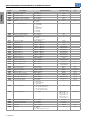
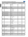
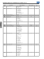
QUICK REFERENCE OF PARAMETERS, ALARMS AND FAULTS
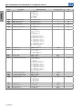
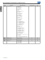
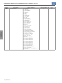
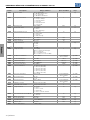
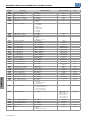
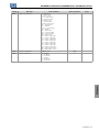
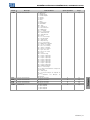
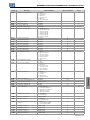
Param. Description Adjustable Range Factory Setting Prop.
P082 Third Fault on Fire Mode 0 to 999 ro
P100 Acceleration Time 0.1 to 999.9 s 5.0 s
P101 Deceleration Time 0.1 to 999.9 s 10.0 s
P102 Acceleration Time 2nd Ramp 0.1 to 999.9 s 5.0 s
P103 Deceleration Time 2nd Ramp 0.1 to 999.9 s 10.0 s
P104 Ramp S 0 = Inactive
1 = Active
0 cfg
P105 1st / 2nd Ramp Selection 0 = 1st Ramp
1 = 2nd Ramp
2 = DIx
3 = Serial/USB
4 = Reserved
5 = CO/DN
6 = SoftPLC
0
P106 Emer. R. Acceleration Time 0.1 to 999.9 s 5.0 s
P107 Emer. R. Time Deceleration 0.1 to 999.9 s 5.0 s
P120 Speed Ref. Backup 0 = Inactive
1 = Active
2 = Backup by P121
1
P121 Reference via HMI 0.0 to 400.0 Hz 3.0 Hz
P122 JOG Reference -400.0 to 400.0 Hz 5.0 Hz
P124 Multispeed Ref. 1 -400.0 to 400.0 Hz 3.0 Hz
P125 Multispeed Ref. 2 -400.0 to 400.0 Hz 10.0 (5.0) Hz
P126 Multispeed Ref. 3 -400.0 to 400.0 Hz 20.0 (10.0) Hz
P127 Multispeed Ref. 4 -400.0 to 400.0 Hz 30.0 (20.0) Hz
P128 Multispeed Ref. 5 -400.0 to 400.0 Hz 40.0 (30.0) Hz
P129 Multispeed Ref. 6 -400.0 to 400.0 Hz 50.0 (40.0) Hz
P130 Multispeed Ref. 7 -400.0 to 400.0 Hz 60.0 (50.0) Hz
P131 Multispeed Ref. 8 -400.0 to 400.0 Hz 66.0 (55.0) Hz
P133 Minimum Frequency 0.0 to 400.0 Hz 3.0 Hz
P134 Maximum Frequency 0.0 to 400.0 Hz 66.0 (55.0) Hz
P135 Maximum Output Current 0.0 to 40.0 A 1,5 x I
nom
V/f
P136 Manual Torque Boost 0.0 to 30.0 % According to the
Inverter Model
V/f
P137 Automatic Torque Boost 0.0 to 30.0 % 0.0 % V/f
P138 Slip Compensation -10.0 to 10.0 % 0.0 % V/f
P139 Output Current Filter 0.000 to 9.999 s 0.050 s V/f, VVW
P140 Slip Com. Filter 0.000 to 9.999 s 0.500 s VVW
P142 Maximum Output Voltage 0.0 to 100.0 % 100.0 % cfg, V/f
P143 Intermediate Output Voltage 0.0 to 100.0 % 50.0 % cfg, V/f
P145 Field Weakening Speed 0.0 to 400.0 Hz 60.0 (50.0) Hz cfg, V/f
P146 Intermediate Frequency 0.0 to 400.0 Hz 30.0 (25.0) Hz cfg, V/f
P149 DC Link Comp. Mode 0 = Inactive
1 = Standard
2 = Overmodulation
3 = Extended
1 cfg, V/f
P150 DC/LC Regul. Type 0 = hold_Ud and decel_LC
1 = accel_Ud and decel_LC
2 = hold_Ud and hold_LC
3 = accel_Ud and hold_LC
0 cfg, V/f, VVW
P151 DC Link Regul. Level 325 to 460 V 430 V (P296 = 1)
380 V (P296 = 2)
781 V (P296 = 4)
781 V (P296 = 5)
781 V (P296 = 6)
781 V (P296 = 7)
V/f, VVW
P156 Rated Speed Overload Current 0.1 to 40.0 A 1,2 x I
nom
P157 Overl.Curr.50 % Speed 0.1 to 40.0 A 1,2 x I
nom
P158 Overl.Curr.20 % Speed 0.1 to 40.0 A 1,2 x I
nom
P178 Rated Flux 50.0 to 150.0 % 100.0 % VVW
P200 Password 0 = Inactive
1 = Active
2 to 9999 = New Password
0 cfg
6 | CFW100

English
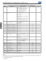
QUICK REFERENCE OF PARAMETERS, ALARMS AND FAULTS
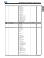
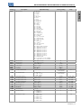
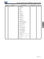
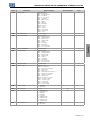
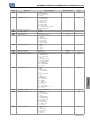
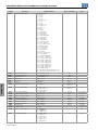
Param. Description Adjustable Range Factory Setting Prop.
P202 Type of Control 0 = V/f
1 = Quadratic V/f
2 to 4 = Not Used
5 = VVW
0 cfg
P204 Load/Save Parameters 0 to 4 = Not Used
5 = Load 60 Hz
6 = Load 50 Hz
7 = Load User
8 = Not Used
9 = Save User
10 = Not Used
11 = Load Default SoftPLC
12 to 13 = Reserved
0 cfg
P205 Main Display Parameter 0 to 999 2
P207 Bar Graph Parameter 0 to 999 3
P208 Ref. Scale Factor 1 to 9999 600
P209 Ref. Eng. Unit 0 to 1 = Without unit
2 = Volt (V)
3 = Hertz (Hz)
4 = Without unit
5 = Percent ( %)
6 = Without unit
7 = Rotation/min. (rpm)
3
P210 Ref. Decimal Point 0 = wxyz
1 = wxy.z
2 = wx.yz
3 = w.xyz
1
P213 Bar Scale Factor 1 to 9999 1,0 x I
nom
P219 Red. Switch. Freq. 0.0 to 15.0 Hz 5.0 Hz cfg
P220 LOC/REM Selection Source 0 = Always Local
1 = Always Remote
2 to 3 = Not Used
4 = DIx
5 = Serial/USB (LOC)
6 = Serial/USB (REM)
7 to 8 = Not Used
9 = CO/DN (LOC)
10 = CO/DN (REM)
11 = SoftPLC
0 cfg
P221 LOC Reference Sel. 0 = HMI
1 = AI1
2 = Not Used
3 = Potentiometer
4 = FI
5 to 6 = Not Used
7 = E.P.
8 = Multispeed
9 = Serial/USB
10 = Not Used
11 = CO/DN
12 = SoftPLC
13 = Not Used
14 = AI1 >0
15 = Not Used
16 = Potentiometer >0
17 = FI >0
0 cfg
P222 REM Reference Selection See options in P221 2 cfg
P223 LOC FWD/REV Selection 0 = Foward
1 = Reverse
2 to 3 = Not Used
4 = DIx
5 = Serial/USB (FWD)
6 = Serial/USB (REV)
7 to 8 = Not Used
9 = CO/DN (FWD)
10 = CO/DN (REV)
11 = Not Used
12 = SoftPLC
0 cfg
P224 LOC Run/Stop Sel. 0 = HMI Keys
1 = DIx
2 = Serial/USB
3 = Not Used
4 = CO/DN
5 = SoftPLC
0 cfg
CFW100 | 7

English
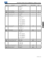
QUICK REFERENCE OF PARAMETERS, ALARMS AND FAULTS
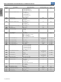
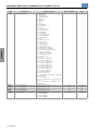
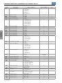
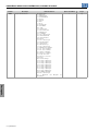
Param. Description Adjustable Range Factory Setting Prop.
P225 LOC JOG Selection 0 = Disabled
1 = Not Used
2 = DIx
3 = Serial/USB
4 = Not Used
5 = CO/DN
6 = SoftPLC
1 cfg
P226 REM FWD/REV Selection See options in P223 4 cfg
P227 REM Run/Stop Selection See options in P224 1 cfg
P228 REM JOG Selection See options in P225 2 cfg
P229 Stop Mode Selection 0 = Ramp to Stop
1 = Coast to Stop
0 cfg
P230 Dead Zone (AIs and FI1 ) 0 = Inactive
1 = Active
0 cfg
P231
(*)
AI1 Signal Function 0 = Speed Ref.
1 to 3 = Not Used
4 = PTC
5 to 6 = Not Used
7 = PLC Use
8 = Application Function 1
9 = Application Function 2
10 = Application Function 3
11 = Application Function 4
12 = Application Function 5
13 = Application Function 6
14 = Application Function 7
15 = Application Function 8
16 = Control Setpoint
17 = Process Variable
0 cfg
P232
(*)
AI1 Input Gain 0.000 to 9.999 1.000
P233
(*)
AI1 Input Signal 0 = 0 to 10 V / 20 mA
1 = 4 to 20 mA
2 = 10 V / 20 mA to 0
3 = 20 to 4 mA
0
P234
(*)
AI1 Input Offset -100.0 to 100.0 % 0.0 %
P235
(*)
AI1 Input Filter 0.00 to 16.00 s 0.00 s
P241
(*)
Potentiometer Signal Function 0 = Speed Ref.
1 to 6 = Not Used
7 = SoftPLC
8 = Application Function 1
9 = Application Function 2
10 = Application Function 3
11 = Application Function 4
12 = Application Function 5
13 = Application Function 6
14 = Application Function 7
15 = Application Function 8
16 to 17 = Not Used
0 cfg
P242
(*)
Potentiometer Signal Gain 0.000 to 9.999 1.000
P244
(*)
Potentiometer Signal Offset -100.0 to 100.0 % 0.0 %
P245 Potentiometer and FI1 Filter 0.00 to 16.00 s 0.00 s
P246 FI1 Input Function 0 = Inactive
1 = Active in DI1
2 = Active in DI2
3 = Active in DI3
4 = Active in DI4
0 cfg
P247 FI1 Input Gain 0.000 to 9.999 1.000
P248 FI1 Minimum Input 1 to 3000 Hz 100 Hz
P249 FI1 Input Offset -100.0 to 100.0 % 0.0 %
P250 FI1 Maximum Input 1 to 3000 Hz 1000 Hz
8 | CFW100

English
QUICK REFERENCE OF PARAMETERS, ALARMS AND FAULTS
Param. Description Adjustable Range Factory Setting Prop.
P251
(*)
AO1 Output Function 0 = Speed Ref.
1 = Not Used
2 = Real Speed
3 to 4 = Not Used
5 = Output Current
6 = Not Used
7 = Active Current
8 to 10 = Not Used
11 = Motor Torque
12 = SoftPLC
13 to 15 = Not Used
16 = Motor Ixt
17 = Not Used
18 = P696 Value
19 = P697 Value
20 = Not Used
21 = Application Function 1
22 = Application Function 2
23 = Application Function 3
24 = Application Function 4
25 = Application Function 5
26 = Application Function 6
27 = Application Function 7
28 = Application Function 8
29 = Control Setpoint
30 = Process Variable
2
P252
(*)
AO1 Output Gain 0.000 to 9.999 1.000
P253
(*)
AO1 Output Signal 0 = 0 to 10 V
1 = 0 to 20 mA
2 = 4 to 20 mA
3 = 10 to 0 V
4 = 20 to 0 mA
5 = 20 to 4 mA
0
P263 DI1 Input Function 0 = Not Used
1 = Run/Stop
2 = General Enable
3 = Quick Stop
4 = Foward Run
5 = Reverse Run
6 = Start
7 = Stop
8 = Direction of Rotation
9 = LOC/REM
10 = JOG
11 = Accelerate E.P.
12 = Decelerate E.P.
13 = Multispeed
14 = 2nd Ramp
15 to 17 = Not Used
18 = No Ext. Alarm
19 = No Ext. Fault
20 = Reset
21 to 23 = Not Used
24 = Disab.FlyStart
25 = Not Used
26 = Lock Prog.
27 to 31 = Not Used
32 = 2nd Ramp Multispeed
33 = 2nd Ramp Increase E.P.
34 = 2nd Ramp Decrease E.P.
35 = 2nd Ramp FWD Run
36 = 2nd Ramp REV Run
37 = Start / Inc. E.P.
38 = Dec. E.P. / Stop
39 = Stop
40 = Safety Switch
41 = Application Function 1
42 = Application Function 2
43 = Application Function 3
44 = Application Function 4
45 = Application Function 5
46 = Application Function 6
47 = Application Function 7
48 = Application Function 8
49 = Enable Fire Mode
50 to 54 = Not Used
55 = Run/Stop with Line Start Lockout
1 cfg
CFW100 | 9

English
QUICK REFERENCE OF PARAMETERS, ALARMS AND FAULTS
Param. Description Adjustable Range Factory Setting Prop.
P264 DI2 Input Function 0 = Not Used
1 = Run/Stop
2 = General Enable
3 = Quick Stop
4 = Foward Run
5 = Reverse Run
6 = Start
7 = Stop
8 = Direction of Rotation
9 = LOC/REM
10 = JOG
11 = Accelerate E.P.
12 = Decelerate E.P.
13 = Multispeed
14 = 2nd Ramp
15 to 17 = Not Used
18 = No Ext. Alarm
19 = No Ext. Fault
20 = Reset
21 to 23 = Not Used
24 = Disab.FlyStart
25 = Not Used
26 = Progr. Off
27 to 31 = Not Used
32 = 2nd Ramp Multispeed
33 = 2nd Ramp Increase E.P.
34 = 2nd Ramp Decrease E.P.
35 = 2nd Ramp FWD Run
36 = 2nd Ramp REV Run
37 = Turn ON / Ac. E.P.
38 = De. E.P. / Turn OFF
39 = Stop
40 = Safety Switch
41 = Application Function 1
42 = Application Function 2
43 = Application Function 3
44 = Application Function 4
45 = Application Function 5
46 = Application Function 6
47 = Application Function 7
48 = Application Function 8
49 = Enable Fire Mode
50 = PID Manual / Automatic
51 to 54 = Not Used
55 = Run/Stop with Line Start Lockout
8 cfg
10 | CFW100

English
QUICK REFERENCE OF PARAMETERS, ALARMS AND FAULTS
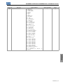
Param. Description Adjustable Range Factory Setting Prop.
P265 DI3 Input Function 0 = Not Used
1 = Run/Stop
2 = General Enable
3 = Quick Stop
4 = Foward Run
5 = Reverse Run
6 = Start
7 = Stop
8 = Direction of Rotation
9 = LOC/REM
10 = JOG
11 = Accelerate E.P.
12 = Decelerate E.P.
13 = Multispeed
14 = 2nd Ramp
15 to 17 = Not Used
18 = No Ext. Alarm
19 = No Ext. Fault
20 = Reset
21 to 23 = Not Used
24 = Disab.FlyStart
25 = Not Used
26 = Lock Prog.
27 to 31 = Not Used
32 = 2nd Ramp Multispeed
33 = 2nd Ramp Increase E.P.
34 = 2nd Ramp Decrease E.P.
35 = 2nd Ramp FWD Run
36 = 2nd Ramp REV Run
37 = Start / Inc. E.P.
38 = Dec. E.P. / Stop
39 = Stop
40 = Safety Switch
41 = Application Function 1
42 = Application Function 2
43 = Application Function 3
44 = Application Function 4
45 = Application Function 5
46 = Application Function 6
47 = Application Function 7
48 = Application Function 8
49 = Enable Fire Mode
50 = Not Used
51 = Command to Increase the Control
Setpoint (EP)
52 = Not Used
53 = 1st DI for Control Setpoint Selection
54 = Not Used
55 = Run/Stop with Line Start Lockout
0 cfg
CFW100 | 11

English
QUICK REFERENCE OF PARAMETERS, ALARMS AND FAULTS
Param. Description Adjustable Range Factory Setting Prop.
P266 DI4 Input Function 0 = Not Used
1 = Run/Stop
2 = General Enable
3 = Quick Stop
4 = Foward Run
5 = Reverse Run
6 = Start
7 = Stop
8 = Direction of Rotation
9 = LOC/REM
10 = JOG
11 = Accelerate E.P.
12 = Decelerate E.P.
13 = Multispeed
14 = 2nd Ramp
15 to 17 = Not Used
18 = No Ext. Alarm
19 = No Ext. Fault
20 = Reset
21 to 23 = Not Used
24 = Disab.FlyStart
25 = Not Used
26 = Progr. Off
27 to 31 = Not Used
32 = 2nd Ramp Multispeed
33 = 2nd Ramp Increase E.P.
34 = 2nd Ramp Decrease E.P.
35 = 2nd Ramp FWD Run
36 = 2nd Ramp REV Run
37 = Start / Inc. E.P.
38 = Dec. E.P. / Stop
39 = Stop
40 = Safety Switch
41 = Application Function 1
42 = Application Function 2
43 = Application Function 3
44 = Application Function 4
45 = Application Function 5
46 = Application Function 6
47 = Application Function 7
48 = Application Function 8
49 = Enable Fire Mode
50 to 51 = Not Used
52 = Command to Decrease the Control
Setpoint (EP)
53 = Not Used
54 = 2nd DI for Control Setpoint Selection
55 = Run/Stop with Line Start Lockout
0 cfg
P267
(*)
DI5 Input Function See options in P263 0 cfg
P268
(*)
DI6 Input Function See options in P263 0 cfg
P269
(*)
DI7 Input Function See options in P263 0 cfg
P270
(*)
DI8 Input Function See options in P263 0 cfg
P271 DIs Function 0 = (DI1..DI8)NPN
1 = (DI1..DI4)PNP
2 = (DI5..DI8)PNP
3 = (DI1..DI8)PNP
0 cfg
12 | CFW100

English
QUICK REFERENCE OF PARAMETERS, ALARMS AND FAULTS
Param. Description Adjustable Range Factory Setting Prop.
P275
(*)
DO1 Function 0 = Not Used
1 = F* ≥ Fx
2 = F ≥ Fx
3 = F ≤ Fx
4 = F = F*
5 = Not Used
6 = Is >Ix
7 = Is <Ix
8 = Torque >Tx
9 = Torque <Tx
10 = Remote
11 = Run
12 = Ready
13 = No Fault
14 = No F070
15 = Not Used
16 = No F021/F022
17 = Not Used
18 = No F072
19 = 4-20 mA OK
20 = P695 Value
21 = Forward
22 to 23 = Not Used
24 = Ride-Through
25 = Pre-Charge OK
26 = Fault
27 = Not Used
28 = SoftPLC
29 to 34 = Not Used
35 = No Alarm
36 = Without fault and alarm
37 = Application Function 1
38 = Application Function 2
39 = Application Function 3
40 = Application Function 4
41 = Application Function 5
42 = Application Function 6
43 = Application Function 7
44 = Application Function 8
45 = Fire Mode ON
46 = Low Level of Process Variable
47 = High Level of Process Variable
13
P276
(*)
DO2 Function See options in P275 0
P277
(*)
DO3 Function See options in P275 0
P281
(*)
Fx Frequency 0.0 to 400.0 Hz 3.0 Hz
P282
(*)
Fx Hysteresis 0.0 to 15.0 Hz 0.5 Hz
P290
(*)
Ix Current 0.0 to 10.0 A 1,0 x I
nom
P293
(*)
Tx Torque 0 to 200 % 100 %
P295 Inverter Rated Current 1.6 to 15.2 A According to the
Inverter Model
ro
P296 Line Rated Voltage 0 = Reserved
1 = 110 - 127 Vac
2 = 200 - 240 Vac
According to the
Inverter Model
ro
P297 Switching Frequency 2.5 to 15.0 kHz 5.0 kHz cfg, V/f, VVW
P299 DC Braking Start Time 0.0 to 15.0 s 0.0 s V/f, VVW
P300 DC Braking Stop Time 0.0 to 15.0 s 0.0 s V/f, VVW
P301 DC Braking Frequency 0.0 to 15.0 Hz 3.0 Hz V/f, VVW
P302 DC Braking Current 0.0 to 100.0 % 20.0 % V/f, VVW
P303 Skip Frequency 1 0.0 to 400.0 Hz 0.0 Hz V/f, VVW
P304 Skip Frequency 2 0.0 to 400.0 Hz 0.0 Hz V/f, VVW
P306 Skip Band 0.0 to 25.0 Hz 0.0 Hz V/f, VVW
P308 Serial Address 1 to 247 1 cfg
P310 Serial Baud Rate 0 = 9600 bits/s
1 = 19200 bits/s
2 = 38400 bits/s
1 cfg
P311 Serial Bytes Config. 0 = 8 bits, no, 1
1 = 8 bits, even,1
2 = 8 bits, odd, 1
3 = 8 bits, no, 2
4 = 8 bits, even,2
5 = 8 bits, odd, 2
1 cfg
CFW100 | 13

English
QUICK REFERENCE OF PARAMETERS, ALARMS AND FAULTS
Param. Description Adjustable Range Factory Setting Prop.
P312 Serial Protocol 0 to 1 = Reserved
2 = Modbus RTU Slave
3 to 4 = Reserved
5 = ModBus RTU Master
2 cfg
P313 Action for Communic. Error 0 = Inactive
1 = Ramp Stop
2 = General Disable
3 = Go to LOC
4 = LOC Keep Enab.
5 = Cause Fault
1
P314 Serial Watchdog 0.0 to 999.0 s 0.0 s cfg
P316 Serial Interf. Status 0 = Inactive
1 = Active
2 = Watchdog Error
ro
P320 Flying Start / Ride-Through 0 = Inactive
1 = Flying Start
2 = FS / RT
3 = Ride-Through
0 cfg
P331 Voltage Ramp for FS and RT 0.2 to 60.0 s 2.0 s
P332 Dead Time 0.1 to 10.0 s 1.0 s
P340 Auto-Reset Time 0 to 255 s 0 s
P352 Fan Control Config. 0 = OFF
1 = ON
2 = CT
2 cfg
P375
(*)
NTC Temperature 0 to 200 ºC ro
P397 Control Config 0 to F (hexa)
Bit 0 = Slip Compens. Regen.
Bit 1 = Reserved
Bit 2 = Is Stabilization
Bit 3 = P297 reduction in A050
1 cfg
P399 Motor Rated Efficiency 50.0 to 99.9 % According to the
Inverter Model
cfg, VVW
P400 Motor Rated Voltage 0 to 240 V 220 V cfg, VVW
P401 Motor Rated Current 0.0 to 10.0 A 1,0 x I
nom
cfg, VVW
P402 Motor Rated Speed 0 to 24000 rpm 1720 rpm cfg, VVW
P403 Motor Rated Frequency 0 to 400 Hz 60 Hz cfg, VVW
P404 Motor Rated Power 0 = 0.16 HP (0.12 kW)
1 = 0.25 HP (0.18 kW)
2 = 0.33 HP (0.25 kW)
3 = 0.50 HP (0.37 kW)
4 = 0.75 HP (0.55 kW)
5 = 1.00 HP (0.75 kW)
2 cfg, VVW
P407 Motor Rated Power Factor 0.50 to 0.99 According to the
Inverter Model
cfg, VVW
P408 Run Self-Tuning 0 = No
1 = Yes
0 cfg, VVW
P409 Stator Resistance 0.01 to 99.99 According to the
Inverter Model
cfg, VVW
P510 SoftPLC Eng. Unit See options in P209 0
P511 SoftPLC Indication Form See options in P210 1
P580 Fire Mode Config 0 = Inactive
1 = Active
2 = Active / P134
3 = Reserved
4 = Active / General Disable
0 cfg
P582 Fire Mode Auto-reset Adjustable 0 = Limited
1 = Unlimited
0 cfg
P588 EOC Maximum Torque 0 to 85 % 0 % cfg
P589 EOC Minimum Voltage 40 to 80 % 40 % cfg
P590 EOC Minimum Frequency 12.0 to 400.0 Hz 20.0 Hz cfg
P591 EOC Hysteresis 0 to 30 % 10 % cfg
P613 Main SW Revision -9999 to 9999 ro
14 | CFW100

English
QUICK REFERENCE OF PARAMETERS, ALARMS AND FAULTS
Param. Description Adjustable Range Factory Setting Prop.
P680 Logical Status 0 to FFFF (hexa)
Bit 0 = Reserved
Bit 1 = Run Command
Bit 2 = Fire Mode
Bit 3 to 4 = Reserved
Bit 5 = 2nd Ramp
Bit 6 = Config. Mode
Bit 7 = Alarm
Bit 8 = Running
Bit 9 = Enabled
Bit 10 = Foward
Bit 11 = JOG
Bit 12 = Remote
Bit 13 = Subvoltage
Bit 14 = Reserved
Bit 15 = Fault
ro
P681 13-Bit Speed 0 to FFFF (hexa) ro
P682 Serial/USB Control 0 to FFFF (hexa)
Bit 0 = Ramp Enable
Bit 1 = General Enable
Bit 2 = Run Forward
Bit 3 = JOG Enable
Bit 4 = Remote
Bit 5 = 2nd Ramp
Bit 6 = Reserved
Bit 7 = Fault Reset
Bit 8 to 15 = Reserved
ro
P683 Serial/USB Speed Ref. 0 to FFFF (hexa) ro
P684
(*)
CO/DN Control 0 to FFFF (hexa)
Bit 0 = Ramp Enable
Bit 1 = General Enable
Bit 2 = Run Forward
Bit 3 = JOG Enable
Bit 4 = Remote
Bit 5 = 2nd Ramp
Bit 6 = Reserved
Bit 7 = Fault Reset
Bit 8 to 15 = Reserved
ro
P685
(*)
CO/DN Speed Ref 0 to FFFF (hexa) ro
P690 Logic State 2 0 to FFFF (hexa)
Bit 0 to 2 = Reserved
Bit 3 = Energy Saver
Bit 4 = Fs Reduction
Bit 5 = Reserved
Bit 6 = Deceleration Ramp
Bit 7 = Acceleration Ramp
Bit 8 = Freeze Ramp
Bit 9 = Setpoint Ok
Bit 10 = DC Link Regulation
Bit 11 = 50 Hz Config
Bit 12 = Ride-Through
Bit 13 = Flying Start
Bit 14 = DC Braking
Bit 15 = PWM pulse
ro
P700
(*)
CAN Protocol 1 = CANopen
2 = DeviceNet
P701
(*)
CAN Address 0 to 127 63
P702
(*)
CAN Baud Rate 0 = 1 Mbps/Auto
1 = Reserved/Auto
2 = 500 Kbps
3 = 250 Kbps
4 = 125 Kbps
5 = 100 Kbps/Auto
6 = 50 Kbps/Auto
7 = 20 Kbps/Auto
8 = 10 Kbps/Auto
0
P703
(*)
Bus Off Reset 0 = Manual
1 = Automatic
1
CFW100 | 15

English
QUICK REFERENCE OF PARAMETERS, ALARMS AND FAULTS
Param. Description Adjustable Range Factory Setting Prop.
P705
(*)
CAN Controller Status 0 = Disabled
1 = Auto-baud
2 = CAN Active
3 = Warning
4 = Error Passive
5 = Bus Off
6 = No Bus Power
ro
P706
(*)
RX CAN Telegrams 0 to 9999 ro
P707
(*)
TX CAN Telegrams 0 to 9999 ro
P708
(*)
Bus Off Counter 0 to 9999 ro
P709
(*)
CAN Lost Messages 0 to 9999 ro
P710
(*)
DeviceNet I/O instances 0 = ODVA Basic 2W
1 = ODVA Extend 2W
2 = Manuf.Spec.2W
3 = Manuf.Spec.3W
4 = Manuf.Spec.4W
5 = Manuf.Spec.5W
6 = Manuf.Spec.6W
0
P711
(*)
DeviceNet Read Word #3 0 to 1199 0
P712
(*)
DeviceNet Read Word #4 0 to 1199 0
P713
(*)
DeviceNet Read Word #5 0 to 1199 0
P714
(*)
DeviceNet Read Word #6 0 to 1199 0
P715
(*)
DeviceNet Write Word #3 0 to 1199 0
P716
(*)
DeviceNet Write Word #4 0 to 1199 0
P717
(*)
DeviceNet Write Word #5 0 to 1199 0
P718
(*)
DeviceNet Write Word #6 0 to 1199 0
P719
(*)
DeviceNet Network Status 0 = Offline
1 = OnLine, NotConn
2 = OnLine, Connect.
3 = Connection Timed out
4 = Link Failure
5 = Auto-Baud
ro
P720
(*)
DeviceNet Master Status 0 = Run
1 = Idle
ro
P721
(*)
CANopen Comm. Status 0 = Disabled
1 = Reserved
2 = Communic. Enabled
3 = Error Ctrl. Enable
4 = Guarding Error
5 = Heartbeat Error
ro
P722
(*)
CANopen Node Status 0 = Disabled
1 = Initialization
2 = Stopped
3 = Operational
4 = Preoperational
ro
P770
(*)
Blueooth Device Name 0 to 9999 Serial Number of the
Inverter
P771
(*)
Bluetooth Password PIN 0 to 9999 1234
P840
(*)
IR Control Command 0 to FFFF (hexa) ro
P842
(*)
Quick View 1 IR 0 to 959 2
P843
(*)
Quick View 2 IR 0 to 959 375
P900 SoftPLC Status 0 = No Application
1 = Installing Application
2 = Incompat. Application
3 = Application Stopped
4 = Application Running
ro
P901 SoftPLC Command 0 = Stop Application
1 = Run Application
0
P902 Scan Cycle Time 0.000 to 9.999 s ro
P903 SoftPLC Appl. 0 = User
1 = PID Controller
1 cfg
P904 Action for SoftPLC Application not
Running
0 = Disabled
1 = Cause Alarm (A708)
2 = Cause Fault (F709)
0
P910 SoftPLC Parameter 1 -9999 to 9999 0
P911 SoftPLC Parameter 2 -9999 to 9999 0
P912 SoftPLC Parameter 3 -9999 to 9999 0
P913 SoftPLC Parameter 4 -9999 to 9999 0
16 | CFW100

English
QUICK REFERENCE OF PARAMETERS, ALARMS AND FAULTS
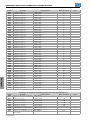
Param. Description Adjustable Range Factory Setting Prop.
P914 SoftPLC Parameter 5 -9999 to 9999 0
P915 SoftPLC Parameter 6 -9999 to 9999 0
P916 SoftPLC Parameter 7 -9999 to 9999 0
P917 SoftPLC Parameter 8 -9999 to 9999 0
P918 SoftPLC Parameter 9 -9999 to 9999 0
P919 SoftPLC Parameter 10 -9999 to 9999 0
P920 SoftPLC Parameter 11 -9999 to 9999 0
P921 SoftPLC Parameter 12 -9999 to 9999 0
P922 SoftPLC Parameter 13 -9999 to 9999 0
P923 SoftPLC Parameter 14 -9999 to 9999 0
P924 SoftPLC Parameter 15 -9999 to 9999 0
P925 SoftPLC Parameter 16 -9999 to 9999 0
P926 SoftPLC Parameter 17 -9999 to 9999 0
P927 SoftPLC Parameter 18 -9999 to 9999 0
P928 SoftPLC Parameter 19 -9999 to 9999 0
P929 SoftPLC Parameter 20 -9999 to 9999 0
P930 SoftPLC Parameter 21 -9999 to 9999 0
P931 SoftPLC Parameter 22 -9999 to 9999 0
P932 SoftPLC Parameter 23 -9999 to 9999 0
P933 SoftPLC Parameter 24 -9999 to 9999 0
P934 SoftPLC Parameter 25 -9999 to 9999 0
P935 SoftPLC Parameter 26 -9999 to 9999 0
P936 SoftPLC Parameter 27 -9999 to 9999 0
P937 SoftPLC Parameter 28 -9999 to 9999 0
P938 SoftPLC Parameter 29 -9999 to 9999 0
P939 SoftPLC Parameter 30 -9999 to 9999 0
P940 SoftPLC Parameter 31 -9999 to 9999 0
P941 SoftPLC Parameter 32 -9999 to 9999 0
P942 SoftPLC Parameter 33 -9999 to 9999 0
P943 SoftPLC Parameter 34 -9999 to 9999 0
P944 SoftPLC Parameter 35 -9999 to 9999 0
P945 SoftPLC Parameter 36 -9999 to 9999 0
P946 SoftPLC Parameter 37 -9999 to 9999 0
P947 SoftPLC Parameter 38 -9999 to 9999 0
P948 SoftPLC Parameter 39 -9999 to 9999 0
P949 SoftPLC Parameter 40 -9999 to 9999 0
P950 SoftPLC Parameter 41 -9999 to 9999 0
P951 SoftPLC Parameter 42 -9999 to 9999 0
P952 SoftPLC Parameter 43 -9999 to 9999 0
P953 SoftPLC Parameter 44 -9999 to 9999 0
P954 SoftPLC Parameter 45 -9999 to 9999 0
P955 SoftPLC Parameter 46 -9999 to 9999 0
P956 SoftPLC Parameter 47 -9999 to 9999 0
P957 SoftPLC Parameter 48 -9999 to 9999 0
P958 SoftPLC Parameter 49 -9999 to 9999 0
P959 SoftPLC Parameter 50 -9999 to 9999 0
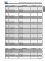
SoftPLC Parameter Configuration for PID Controller Application (P903 = 1)
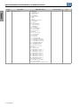
Param. Description Adjustable Range Factory Setting Prop.
P910 PID Controller Application Version 0.00 to 90.00 ro
P911 Control Setpoint -99.99 to 99.99 2.00
P912 Control Setpoint 1 -99.99 to 99.99 2.00
P913 Control Setpoint 2 -99.99 to 99.99 2.30
P914 Control Setpoint 3 -99.99 to 99.99 1.80
P915 Control Setpoint 4 -99.99 to 99.99 1.60
P916 Control Process Variable -99.99 to 99.99 ro
P917 PID Controller Output 0.0 to 100.0 % ro
P918 PID Controller Setpoint in Manual
Mode
0.0 to 400.0Hz 0.0Hz
CFW100 | 17

English
QUICK REFERENCE OF PARAMETERS, ALARMS AND FAULTS
SoftPLC Parameter Configuration for PID Controller Application (P903 = 1)
Param. Description Adjustable Range Factory Setting Prop.
P919 PID Controller Logical Status 0 to FFFF (hexa)
Bit 0 = Sleep Mode Active (A750)
Bit 1 = PID in Manual (0) / Automatic (1)
Bit 2 = PV Low Level (A760)
Bit 3 = PV Low Level (F761)
Bit 4 = PV High Level (A762)
Bit 5 = PV High Level (F763)
Bit 6 to 15 = Reserved
ro
P920 Selection of the Control Setpoint
Source
0 = Control Setpoint via HMI or
Communication Networks (P911)
1 = Control Setpoint via Analog Input AI1
2 = Not Used
3 = Control Setpoint via Electronic
Potentiometer (EP)
4 = Two Setpoints via Digital Input DI3
(P912 and P913)
5 = Three Setpoints via Digital Inputs DI3
and DI4 (P912, P913 and P914)
6 = Four Setpoints via Digital Inputs DI3
and DI4 (P912, P913, P914 and P915)
0 cfg
P921 Selection of the Control Process
Variable Source
1 = Control Process Variable via Analog
Input AI1
2 = Not Used
3 = Not Used
1 cfg
P922 Minimum Sensor Level of the
Control Process Variable
-99.99 to 99.99 0.00
P923 Maximum Sensor Level of the
Control Process Variable
-99.99 to 99.99 4.00
P924 Value for Low Level Alarm for the
Control Process Variable
-99.99 to 99.99 1.00
P925 Time for Low Level Fault for the
Control Process Variable
0.0 to 999.9s 0.0s
P926 Value for High Level Alarm for the
Control Process Variable
-99.99 to 99.99 3.50
P927 Time for High Level Fault for the
Control Process Variable
0.0 to 999.9s 0.0s
P928 Selection of the PID Controller
Control Action
0 = Disable PID Controller
1 = Enable PID Controller in Direct Mode
2 = Enable PID Controller in Reverse Mode
0 cfg
P929 PID Controller Operation Mode 0 = Manual
1 = Automatic
2 = Select Control to Manual (0) or
Automatic (1) via digital input DI2
2
P930 Automatic Adjustment of the PID
Controller Setpoint
0 = P911 inactive and P918 inactive
1 = P911 active and P918 inactive
2 = P911 inactive and P918 active
3 = P911 active and P918 active
0
P931 Proportional Gain 0.00 to 99.99 1.00
P932 Integral Gain 0.00 to 99.99 5.00
P933 Derivative Gain 0.00 to 99.99 0.00
P934 PID Controller Sampling Period 0.050 to 9.999s 0.100s cfg
P935 Filter for the PID Controller Control
Setpoint
0.000 to 9.999s 0.150s
P936 Deviation of the Control Process
Variable to Wake Up
-99.99 to 99.99 0.30
P937 Time to Wake Up 0.0 to 999.9s 5.0s
P938 Motor Speed to activate the Sleep
Mode
0.0 to 400.0Hz 0.0Hz
P939 Time to activate de Sleep Mode 0.0 to 999.9s 10.0s
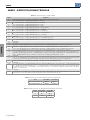
Notes:
(*) Only available when IO or communication expansion accessory is present (connected). For further information,
refer to the respective accessory guide.
ro = Read only parameter
cfg = Configuration parameter, value can be programmed only with motor stopped
V/f = Available when V/f control mode is chosen
VVW = Available when VVW control mode is chosen
18 | CFW100

English
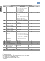
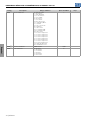
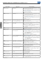
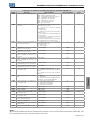
QUICK REFERENCE OF PARAMETERS, ALARMS AND FAULTS
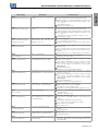
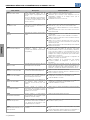
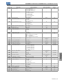
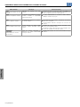
Fault / Alarm Description Possible Causes
F021
Undervoltage on the DC Link
Undervoltage fault on the intermediate
circuit.
Wrong voltage supply; check if the data on the inverter label
comply with the power supply and parameter P296.
Supply voltage too low, producing voltage on the DC Link
below the minimum value (Level F021) according to Table
1.2 on page 23.
Phase fault in the input.
Fault in the pre-charge circuit.
F022
Overvoltage on the DC Link
Overvoltage fault on the intermediate
circuit.
Wrong voltage supply; check if the data on the inverter label
comply with the power supply and parameter P296.
Supply voltage is too high, producing voltage on the DC Link
above the maximum value (Level F022) according to Table
1.2 on page 23.
Load inertia is too high or deceleration ramp is too fast.
P151 setting is too high.
F031
Fault in Communication with
Expansion Accessory
Main control cannot establish the
communication link with the IOs
expansion accessory.
Accessory damaged.
Poor connection of the accessory.
Problem in the identification of the accessory; refer to P027.
F033
VVW Self-tuning Fault
Stator resistance setting fault P409.
Stator resistance value in P409 does not comply with the
inverter power.
Motor connection error; turn off the power supply and check
the motor terminal box and the connections with the motor
terminals.
Motor power too low or too high in relation to the inverter.
A046
Motor Overload
Motor overload alarm.
Settings of P156 is too low for the used motor.
Overload on the motor shaft.
A050
IGBTs Overtemperatures
Overtemperature alarm from the power
module temperature sensor (NTC).
High temperature at IGBTs. P030 >Level A050, according
to Table 1.3 on page 23.
High ambient temperature around the inverter and high
output current. For further information, refer to of the
user’s manual available for download on the website:
www.weg.net.
Blocked or defective fan.
Heatsink is too dirty, preventing the air flow.
F051
IGBTs Overtemperatures
Overtemperature fault measured on the
temperature sensor of the power pack.
High temperature at IGBTs. P030 >Level F051, according to
Table 1.3 on page 23.
High ambient temperature around the inverter and high
output current. For further information, refer to of the
user’s manual available for download on the website:
www.weg.net.
Blocked or defective fan.
Heatsink is too dirty, preventing the air flow.
F070
Overcurrent/Shortcircuit
Overcurrent or short-circuit on the
output, DC Link or braking resistor.
Short-circuit between two motor phases.
IGBTs module in short-circuit or damaged.
Start with too short acceleration ramp.
Start with motor spinning without the Flying Start function.
F072
Motor Overload
Motor overload fault.
P156, P157 or P158 setting is too low in relation to the motor
operating current.
Overload on the motor shaft.
F078
Motor Overtemperature
Overtemperature fault measured on the
motor temperature sensor (Triple PTC)
via analog input AIx
Overload on the motor shaft.
Load cycle is too high (high number of starts and stops per
minute).
High ambient temperature around the motor.
Poor contact or short-circuit (3k9 <R
PTC
<0k1).
Motor thermistor not installed.
Motor shaft is stuck.
F079
Encoder Signal Fault
Fault of encoder signals absent.
Wiring between encoder and interface accessory to encoder
broken.
Encoder defective.
F080
CPU Fault (Watchdog)
Fault related to the supervision
algorithm of the inverter main CPU.
Electric noise.
Inverter firmware fault.
F081
End of User’s Memory
Fault of end of memory to save user’s
parameter table.
Attempt to save (P204 = 9) more than 32 parameters
(with values different from the factory default) on the User
parameter table.
CFW100 | 19

English
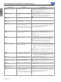
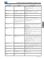
QUICK REFERENCE OF PARAMETERS, ALARMS AND FAULTS
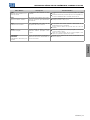
Fault / Alarm Description Possible Causes
F082
Fault in Data Transfer (MMF)
Fault in data transfer using MMF
accessory.
Attempt to download data from the flash memory module to
the inverter with the inverter energized.
Attempt to download a SoftPLC application incompatible
with the destination inverter.
Problems saving data downloaded to the inverter.
F084
Auto-diagnosis Fault
Fault related to the automatic
identification algorithm of the inverter
hardware.
Poor contact in the connection between the main control
and the power pack.
Hardware not compatible with the firmware version.
Defect on the internal circuits of the inverter.
A090
External Alarm
External alarm via DIx (option “no
external alarm” in P263 to P270).
Wiring on DI1 to DI8 inputs are open or have poor contact.
F091
External Fault
External fault via DIx (“no external fault”
in P263 to P270).
Wiring on DI1 to DI8 inputs are open or have poor contact.
A128
Telegram Reception Timeout
It indicates that the device stopped
receiving valid telegrams for a period
longer than the setting in P314.
The time counting starts as soon as
it receives the first valid telegram, with
correct address and error-checking
field.
Check network installation, broken cable or fault/poor
contact on the connections with the network, grounding.
Ensure the master always sends telegrams to the equipment
in a time shorter than the setting in P314.
Disable this function in P314.
A133
No Power Supply on the CAN
Interface
It indicates that the CAN interface has
no power supply between pins 25 and
29 of the connector.
Measure if there is voltage within the allowed range between
pins 25 and 29 of the CAN interface connector.
Check if the power supply cables are not misconnected or
inverted.
Check for contact problems on the cable or connector of
the CAN interface.
A134
Bus Off
Bus off error detected on the CAN
interface.
Check for short circuit on the CAN circuit transmission cable.
Check if the cables are not misconnected or inverted.
Check if all the network devices use the same baud rate.
Check if the termination resistors with the right specification
were installed only at the end of the main bus.
Check if the CAN network was properly installed.
A135
Node Guarding/ Heartbeat
CANopen communication error control
detected communication error using
the guarding mechanism.
Check the times set on the master and on the slave for
message exchange. In order to prevent problems due to
transmission delays and time counting, it is recommended
that the values set for error detection by the slave be
multiples of the times set for message exchange on the
master.
Check if the master is sending the guarding telegrams in the
time set.
Check problems in the communication that may cause
missing telegrams or transmission delays.
A136
Idle Master
Alarm indicates that the DeviceNet
network master is in Idle mode.
Set the switch that controls the master operation of the
master for Run or the corresponding bit on the configuration
word of the master software. If further information is needed,
refer to the documentation of the master used.
A137
DeviceNet Connection Timeout
Alarm that indicates that one or more
DeviceNet connections timed out.
Check the network master status.
Check network installation, broken cable or fault/poor
contact on the connections with the network.
A163
Signal Fault AI1 4...20 mA
Analog input signal AI1 at 4 to 20 mA
or 20 to 4 mA is below 2 mA.
Current signal on the analog input AI1 interrupted or null.
Parameterization error on analog input AI1.
A177
Replace Fan
Alarm to replace the fan (P045 >50000
hours).
Maximum number of operation hours of the heatsink fan
exceeded.
A211
Drive in Fire Mode
Indicates that the drive is in Fire Mode.
The digital input programmed for activating the Fire Mode is
active.
F228
Telegram Reception Timeout
It indicates that the device stopped
receiving valid telegrams for a period
longer than the setting in P314.
The time counting starts as soon as
it receives the first valid telegram, with
correct address and error-checking
field.
Check network installation, broken cable or fault/poor
contact on the connections with the network, grounding.
Ensure the master always sends telegrams to the equipment
in a time shorter than the setting in P314.
Disable this function in P314.
20 | CFW100
A página está carregando...
A página está carregando...
A página está carregando...
A página está carregando...
A página está carregando...
A página está carregando...
A página está carregando...
A página está carregando...
A página está carregando...
A página está carregando...
A página está carregando...
A página está carregando...
A página está carregando...
A página está carregando...
A página está carregando...
A página está carregando...
A página está carregando...
A página está carregando...
A página está carregando...
A página está carregando...
A página está carregando...
A página está carregando...
A página está carregando...
A página está carregando...
A página está carregando...
A página está carregando...
A página está carregando...
A página está carregando...
A página está carregando...
A página está carregando...
A página está carregando...
A página está carregando...
A página está carregando...
A página está carregando...
A página está carregando...
A página está carregando...
A página está carregando...
A página está carregando...
A página está carregando...
A página está carregando...
A página está carregando...
A página está carregando...
A página está carregando...
A página está carregando...
A página está carregando...
A página está carregando...
A página está carregando...
A página está carregando...
A página está carregando...
A página está carregando...
-
 1
1
-
 2
2
-
 3
3
-
 4
4
-
 5
5
-
 6
6
-
 7
7
-
 8
8
-
 9
9
-
 10
10
-
 11
11
-
 12
12
-
 13
13
-
 14
14
-
 15
15
-
 16
16
-
 17
17
-
 18
18
-
 19
19
-
 20
20
-
 21
21
-
 22
22
-
 23
23
-
 24
24
-
 25
25
-
 26
26
-
 27
27
-
 28
28
-
 29
29
-
 30
30
-
 31
31
-
 32
32
-
 33
33
-
 34
34
-
 35
35
-
 36
36
-
 37
37
-
 38
38
-
 39
39
-
 40
40
-
 41
41
-
 42
42
-
 43
43
-
 44
44
-
 45
45
-
 46
46
-
 47
47
-
 48
48
-
 49
49
-
 50
50
-
 51
51
-
 52
52
-
 53
53
-
 54
54
-
 55
55
-
 56
56
-
 57
57
-
 58
58
-
 59
59
-
 60
60
-
 61
61
-
 62
62
-
 63
63
-
 64
64
-
 65
65
-
 66
66
-
 67
67
-
 68
68
-
 69
69
-
 70
70


WEG CFW100 Guia rápido
- Tipo
- Guia rápido
- Este manual também é adequado para
em outras línguas
- español: WEG CFW100 Guía de inicio rápido
Artigos relacionados
-
WEG CFW300 Guia rápido
-
WEG CFW100 Guia de instalação
-
-
-
-
-
-
 Automation Direct CFW100-IOP Guia de usuario
-
-

Outros documentos
-
Epson SureColor P700 Informação importante
-
koban KTFD-29 Manual do proprietário
-
Omega Série CN1514/CN1517 Manual do proprietário
-
PORCELANOSA RONDO. 100259092 Guia de instalação
-
 Hexagon HxGN AgrOn Sprayer Control Manual do usuário
-
ABB NIESSEN 8131 Guia rápido
-
Premier MC-5303 Manual do usuário
-
Bosch PPW2250/01 Manual do proprietário
-
Dri-Eaz AirWolf Airmover Manual do usuário
