
Subwoofer
MODEL
CO104S
CO124S
CO154S
OWNER'S MANUAL
™
Vista, CA 92801
D I R E C T E D . C O M

© 2007 directed electronics—all rights reserved 1
TABLE OF CONTENTS
English . . . . . . . . . . . . . . . . . . . . . . . . . . . . . . . . . . . . . . . . . . . . . . . . . . . . . . . . . . . . . . . 1
Français . . . . . . . . . . . . . . . . . . . . . . . . . . . . . . . . . . . . . . . . . . . . . . . . . . . . . . . . . . . . . 17
Español. . . . . . . . . . . . . . . . . . . . . . . . . . . . . . . . . . . . . . . . . . . . . . . . . . . . . . . . . . . . . . 25
Deutsche . . . . . . . . . . . . . . . . . . . . . . . . . . . . . . . . . . . . . . . . . . . . . . . . . . . . . . . . . . . . 33
Italiano. . . . . . . . . . . . . . . . . . . . . . . . . . . . . . . . . . . . . . . . . . . . . . . . . . . . . . . . . . . . . . 41
Português . . . . . . . . . . . . . . . . . . . . . . . . . . . . . . . . . . . . . . . . . . . . . . . . . . . . . . . . . . . 49
Introduction . . . . . . . . . . . . . . . . . . . . . . . . . . . . . . . . . . . . . . . . . . . . . . . . . . . . . . . 1
Practice Safe Sound™ . . . . . . . . . . . . . . . . . . . . . . . . . . . . . . . . . . . . . . . . . . . . . . . . 1
Whats in the box . . . . . . . . . . . . . . . . . . . . . . . . . . . . . . . . . . . . . . . . . . . . . . . . . . . . .1
Installation . . . . . . . . . . . . . . . . . . . . . . . . . . . . . . . . . . . . . . . . . . . . . . . . . . . . . . . . . 2
Tools of the Trade . . . . . . . . . . . . . . . . . . . . . . . . . . . . . . . . . . . . . . . . . . . . . . . . . . . 2
Finding Speaker Mounting Locations . . . . . . . . . . . . . . . . .. . . . . . . . . . . . . . . . . . . . 2
Features . . . . . . . . . . . . . . . . . . . . . . . . . . . . . . . . . . . . . . . . . . . . . . . . . . . . . . . . . . 3
Wiring Configurations . . . . . . . . . . . . . . . . . . . . . . . . . . . . . . . . . . . . . . . . . . . . . . . . . 4
Enclosure Recommendations . . . . . . . . . . . . . . . . . . . . . . . . . . . . . . . . . . . . . . . . . . . 8
Specifications . . . . . . . . . . . . . . . . . . . . . . . . . . . . . . . . . . . . . . . . . . . . . . . . . . . . . . 14
Warranty . . . . . . . . . . . . . . . . . . . . . . . . . . . . . . . . . . . . . . . . . . . . . . . . . . Back cover
INTRODUCTION
Thank you for your purchase of the Orion Cobalt Subwoofers. These woofers
represent a combination of incredible performance and value. We at Orion strive to
give you the latest up to date information about this product. What we can’t give you
with the manual is personal installation or technical experience. If you have questions
concerning the use or application of this product please refer to the nearest ORION
dealer for assistance, visit www.orioncaraudio.com, or call the technical support
hotline at 1-800-876-0800. As we are always finding new ways to improve our product,
the features and specifications are subject to change without notice.
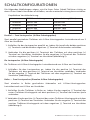
PRACTICE SAFE SOUND™
Continuous exposure to sound pressure levels over 100dB may cause permanent
hearing loss. High powered automotive sound systems can generate sound pressure
levels in excess of 130dB. When playing your system at high levels, please use hearing
protection and prevent long term exposure.
Model Number: _______________
Serial Number: _______________
Date of Purchase: _______________

2 © 2007 directed electronics—all rights reserved
WHAT’S IN THE BOX
Included in this box are all the necessary mounting hardware and cables for your basic
installation. Listed below is a detailed list of the components included in this system
package.
Quantity Description
1 Installation and Operation Manual
1 Orion
TM
Cobalt woofer
1 Mounting template Mounting screws
INSTALLATION
The performance of these Cobalt subwoofers is directly proportional to the quality
of the installation. Care taken with the installation process will be rewarded by
years of satisfying performance. If you are unsure of your installation abilities, please
refer to your local authorized ORION dealer for assistance. Orion dealers are trained
professionals dedicated to extracting the maximum performance out of your Orion
system. If you decide to install this speaker system yourself, please read the entire
section on sealed and vented enclosures before starting the installation. .
TOOLS OF THE TRADE
Listed are the majority of the tools required to perform the installation. Having the
proper tools will make the installation much easier. It is very difficult when you get
half way through the installation and discover that you require a specific tool to
get yourself through a particular part of the installation. Some of these tools are
necessities. Some make the job much easier.
• Marking Pen • Electric Drill and assorted Bits
• Phillips Screwdriver • Wire Strippers
• Allen Wrenches • Volt/Ohm Meter (Optional)
• Table Saw • Jig Saw
• Wire Cutters • Wire Crimpers
FINDING SPEAKER MOUNTING LOCATIONS
Choosing the correct speaker locations will have the greatest effect on the
sound quality of the system. Different considerations are needed when choosing
the locations that best suit your needs. The locations must be large enough for
the speakers to fit. Care is needed to ensure that the location you have chosen
will not affect any of the mechanical or electrical operations of the vehicle.
Determining the best location for the speakers will depend on your cosmetic needs
and your vehicle's interior. If minimal intrusion in your vehicle is desired, factory
speaker locations may be the ticket for you. These woofers are too large to fit most
factory locations and typically need enclosures to perform correctly.

© 2007 directed electronics—all rights reserved 3
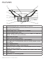
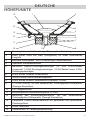
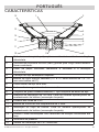
FEATURES
13
12
15
14
11
10 9
1 2
3
6
5
7
4
8
CC
1 Polypropylene dust cap - moisture and UV resistant.
2 Oversized NBR (Nitrile-butadiene Rubber) surround for linear
controlled long excursion.
3 Vented paper cone - moisture and UV resistant.
4 Custom stamped steel frame.
5 Vented Kapton voice coil former (10” & 12" uses 1.5" voice coil
former, 15” use a 2" voice coil former).
6 8mm steel front plate.
7 Large 2 stack ceramic magnets.
8 8mm steel back plate/pole piece T yoke assembly.
9 .75" vent. Part of the enhanced voice coil cooling system (forced
convection).
10 PVC magnet protector.
11 High temperature Copper 4 ohm voice coil.
12 Venting in voice coil former. Part of the enhanced voice coil cooling
system (forced convection).
13 Interlaced Conex spider with stitched and looped tinsel leads
attached.
14 Push Terminals.
15 Reversible PVC mounting gasket.

4 © 2007 directed electronics—all rights reserved
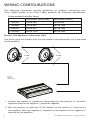
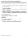
WIRING CONFIGURATIONS
The following illustrations provide guidelines on properly connecting your
Orion Cobalt woofer to an Orion Cobalt amplifier for maximum performance.
Recommended Amplifier Power
Continuous Power (RMS) Peak Power (Watts)
1 woofer 100 to 300 200 to 600
2 woofers 200 to 600 400 to 1200
3 woofers 300 to 900 600 to 1800
4 woofers 400 to 1200 800 to 2400
Parallel—Two Speakers ( 4 ohm voice coils)
Two 4 ohm voice coil woofers with the two woofers in parallel results in a 2 ohm load
to the amplifier..
+
+
+
4 ohm
_
_
_
4 ohm
Figure 2
Figura 2
Abbildung 2
1. Connect the speaker in parallel by connecting the two positive (+) terminals
together and the two negative (-) terminals together.
2. Wire the positive (+) terminals of the woofers to the positive (+) terminal on
the amplifier. Wire the negative (-) terminals of the woofers to the negative (-)
terminal on the amplifier.

© 2007 directed electronics—all rights reserved 5
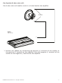
One Speaker (4 ohm voice coil)
One 4 ohm voice coil woofer results in a 4 ohm load to the amplifier.
+
+
4 ohm
_
_
Figure 3
Figura 3
Abbildung 3
1. Connect the speaker by connecting the positive (+) terminal of the woofer to
the positive (+) terminal on the amplifier. Wire the negative (-) terminal of the
woofer to the negative (-) terminal on the amplifier.

6 © 2007 directed electronics—all rights reserved
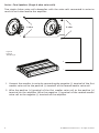
Series—Two Speakers (Single 4 ohm voice coils)
Two single 4 ohm voice coil subwoofers with the voice coils connected in series to
result in an 8 ohm load to the amplifier.
+
+
+
4 ohm
_
_
_
4 ohm
Figure 4
Figura 4
Abbildung 4
1. Connect the woofers in series by connecting the negative (-) terminal of the first
woofer voice coil to the positive (+) terminal of the second woofer voice coil.
2. Wire the positive (+) terminal of the first woofer voice coil to the positive (+)
terminal on the amplifier. Wire the negative (-) terminal of the second woofer
voice coil to the negative (-) terminal on the amplifier.

© 2007 directed electronics—all rights reserved 7
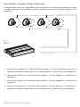
Series/Parallel - 4 Speakers (Single 4 Ohm Coils)
4 single 4 ohm voice coil subwoofers with the voice coils of each pair of speaker wired
in series and then all 4 speakers wired in parallel to result in a 4 ohm load on the
amplifier.
+
+
+
4 ohm
_
_
_
4 ohm
+
+
4 ohm
_
4 ohm
_
1 2 3 4
Figure 5
Figura 5
Abbildung 5
1. Connect the negative (-) terminal from speaker 1 to the negative terminal on
speaker 3 and then hook that wire to the negative (-) terminal on the amplifier.
2. Connect the positive (+) terminal from speaker 1 to the negative (-) terminal on
speaker 2.
3. Connect the positive (+) terminal from speaker 3 to the negative (-) terminal on
speaker 4.
4. Connect the positive (+) terminal from speaker 2 to the positive (+) terminal on
speaker 4 and then hook that wire to the positive (+) terminal on the amplifer.

8 © 2007 directed electronics—all rights reserved
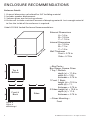
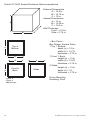
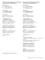
ENCLOSURE RECOMMENDATIONS
Enclosure Details
1. External dimensions calculated for 3/4” building material
2. Includes speaker displacement
3. Volumes given are net tuning volume
4. Enclosures include a minimal amount of damping material. Just enough material
to line the inside of the enclosure is required.
Cobalt CO104S Sealed Enclosure Recommendations
c
b
—Box Parts—
Box Shape: Square Prism
1 Top, 1 Bottom:
depth (c) = 11.5 in
width (b) = 12.5,
thickness = 0.75 in
1 Front, 1 Back:
height (a) = 12.5 in
width (d) = 11,
thickness = 0.75 in
2 Sides: height (a) = 12.5 in
depth (c) = 11.5,
thickness = 0.75 in
—Driver Mounting—
Front
Top &
Bottom
a
d
Front &
Back
c
Sides
A
B
C
External Dimensions
A = 14 in
B = 12.5 in
C = 11.5 in
Internal Dimensions
A = 12.5 in
B = 11 in
C = 10 in
Wall Thickness
Front = 0.75 in
Side = 0.75 in
Figure 6
Figura 6
Abbildung 6

© 2007 directed electronics—all rights reserved 9
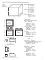
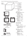
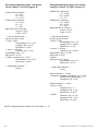
Cobalt CO104S Vented Enclosure Recommendations
—Box Parts—
Box Shape: Square Prism
1 Top, 1 Bottom:
depth (c) = 12 in
width (b) = 14.25,
thickness = 0.75 in
1 Front, 1 Back:
height (a) = 14.25 in
width (d) = 12.75,
thickness = 0.75 in
2 Sides:
height (a) = 14.25 in
depth (c) = 12,
thickness = 0.75 in
—Driver Mounting—
Front
Vent Parts --- Round
1 Duct: outside diameter (e) = 3.25 in
inside diameter (g) = 3 in
length (h) = 9.5 in
Vent Parts --- Square
1 Top, 1 Bottom:
width (e) = 3,
length (h) = 10 in
thickness = 0.125 in
2 Sides:
height (g) = 2.75,
length (h) = 10 in
thickness = 0.125 in
c
b
Top &
Bottom
a
e
d
Front &
Back
c
Sides
h
h
VENT Round
- OR -
VENT Square
e
h
g
g
A
B
C
External Dimensions
A = 15.75 in
B = 14.25 in
C = 12 in
Internal Dimensions
A = 14.25 in
B = 12.75 in
C = 10.5 in
Wall Thickness
Front = 0.75 in
Side = 0.75 in
Figure 7
Figura 7
Abbildung 7

10 © 2007 directed electronics—all rights reserved
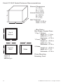
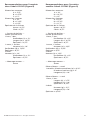
Cobalt CO124S Sealed Enclosure Recommendations
c
b
—Box Parts—
Box Shape: Square Prism
1 Top, 1 Bottom:
depth (c) = 12 in
width (b) = 14.75,
thickness = 0.75 in
1 Front, 1 Back:
height (a) = 14 in
width (d) = 13.25,
thickness = 0.75 in
2 Sides:
height (a) = 14 in
depth (c) = 12,
thickness = 0.75 in
Driver Mounting
Mounting: Front
Top &
Bottom
a
d
Front &
Back
c
Sides
A
B
C
External Dimensions
A = 15.5 in
B = 14.75 in
C = 12 in
Internal Dimensions
A = 14 in
B = 13.25 in
C = 10.5 in
Wall Thickness
Front = 0.75 in
Side = 0.75 in
Figure 8
Figura 8
Abbildung 8

© 2007 directed electronics—all rights reserved 11
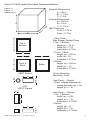
Cobalt CO124S Vented Enclosure Recommendations
—Box Parts—
Box Shape: Square Prism
1 Top, 1 Bottom:
depth (c) = 13 in
width (b) = 16.75,
thickness = 0.75 in
1 Front, 1 Back:
height (a) = 16.5 in
width (d) = 15.25,
thickness = 0.75 in
2 Sides:
height (a) = 16.5 in
depth (c) = 13,
thickness = 0.75 in
Driver Mounting
Mounting: Front
Vent Parts --- Round
1 Duct:
outside diameter (e) = 4.25 in
inside diameter (g) = 4 in
length (h) = 10 in
Vent Parts --- Square
1 Top, 1 Bottom:
width (e) = 3.75,
length (h) = 10 in
thickness = 0.125 in
2 Sides:
height (g) = 3.5,
length (h) = 10 in
thickness = 0.125 in
c
b
Top &
Bottom
a
e
d
Front &
Back
c
Sides
h
h
VENT Round
- OR -
VENT Square
e
h
g
g
A
B
C
External Dimensions
A = 18 in
B = 16.75 in
C = 13 in
Internal Dimensions
A = 16.5 in
B = 15.25 in
C = 11.5 in
Wall Thickness
Front = 0.75 in
Side = 0.75 in
Figure 9
Figura 9
Abbildung 9

12 © 2007 directed electronics—all rights reserved
Cobalt CO154S Sealed Enclosure Recommendations
c
b
—Box Parts—
Box Shape: Square Prism
1 Top, 1 Bottom:
depth (c) = 11.5 in
width (b) = 17.5,
thickness = 0.75 in
1 Front, 1 Back:
height (a) = 23.5 in
width (d) = 16,
thickness = 0.75 in
2 Sides:
height (a) = 23.5 in
depth (c) = 11.5,
thickness = 0.75 in
Driver Mounting
Mounting: Front
Top &
Bottom
a
d
Front &
Back
c
Sides
A
B
C
External Dimensions
A = 25 in
B = 17.5 in
C = 11.5 in
Internal Dimensions
A = 23.5 in
B = 16 in
C = 10 in
Wall Thickness
Front = 0.75 in
Side = 0.75 in
Figure 10
Figura 10
Abbildung 10

© 2007 directed electronics—all rights reserved 13
Cobalt CO154S Vented Enclosure Recommendations
—Box Parts—
Box Shape: Square Prism
1 Top, 1 Bottom:
depth (c) = 13 in
width (b) = 17.5,
thickness = 0.75 in
1 Front, 1 Back:
height (a) = 23.5 in
width (d) = 16,
thickness = 0.75 in
2 Sides:
height (a) = 23.5 in
depth (c) = 13,
thickness = 0.75 in
Driver Mounting
Mounting: Front
Vent Parts --- Round
1 Duct: outside diameter (e) = 4.25 in
inside diameter (g) = 4 in
length (h) = 7 in
Vent Parts --- Square
1 Top, 1 Bottom:
width (e) = 4.25,
length (h) = 7 in
thickness = 0.125 in
2 Sides:
height (g) = 4,
length (h) = 7 in
thickness = 0.125 in
c
b
Top &
Bottom
a
e
d
Front &
Back
c
Sides
h
h
VENT Round
- OR -
VENT Square
e
h
g
g
A
B
C
External Dimensions
A = 25 in
B = 17.5 in
C = 13 in
Internal Dimensions
A = 23.5 in
B = 16 in
C = 11.5 in
Wall Thickness
Front = 0.75 in
Side = 0.75 in
Figure 11
Figura 11
Abbildung 11

14 © 2007 directed electronics—all rights reserved
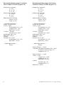
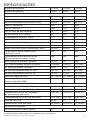
SPECIFICATIONS
Directed Part Number CO104S CO124S CO154S
Model Number 32100 32105 32115
Thiele/Small Parameters
Fs (free-air resonance, Hz) 39.2 25.6 25.2
Vas (equivalent compliance, cu. ft.) 1.080 4.017 7.098
Vas (equivalent compliance, liters) 30.600 113.790 201.070
Qms (Q, mechanical) 3.53 4.72 6.08
Qes (Q, electrical) 0.68 0.55 0.51
Qts (total driver Q) 0.57 0.49 0.47
Re (DC resistance, ohms) 3.6 3.55 3.77
Z (nominal impedance, ohms) 4 4 4
Le (inductance, mh) 1.38 1.37 1.61
Efficiency (1W @ 1M, dB) 86.1 87.2 89.9
Xmax (one way linear excursion, in.) 0.406 0.410 0.453
Xmax (one way linear excursion, mm) 10.2925 10.4075 11.5
Pe (continuous power handling,
watts)
200 200 250
Peak power handling (music, watts) 400 500 600
Mms (total moving mass, grams) 101.00 127 195
Cms (mechanical compliance, mm/N) 0.180564 0.294721 0.211994
Bl (motor strength, Tesla-M) 10.88 11.61 14.82
Sd (effective radiating area, sq. cm.) 346.361 522.792 819.398
Sd (effective radiating area, sq. in.) 53.706 81.064 127.055
Frequency range (Hz) 39 - 250Hz 25 - 250Hz 25 - 250Hz
Energy Bandwidth Product (EBP) 58 47 49
Driver Physical Dimension
Speaker Displacement (cu ft) 0.048 0.061 0.116
Speaker Outer Diameter (inches/mm) 10.31/ 262 12.40/ 315 15.40/ 391
Mounting hole diameter (inches/mm) 9.23/ 232 10.91/ 277 13.82/ 351
Mounting depth (inches/mm) 5.12/ 130 5.51/ 140 6.46/ 164
Magnet Weight (Oz) 38.60 41 70
Basket diameter (inches/mm) 10.16/258 12.21/310 15.16/385
Recommended Enclosures
Typical sealed enclosure (cu. ft.) 0.75 1 2
Specifications subject to change without notice

© 2007 directed electronics—all rights reserved 15
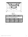
D
A
E
C
B
Figure 12
Figura 12
Abbildung 12
CO104S CO124S CO154S
Dimensions inches/mm, Dimensions po/mm, Dimensiones
plg./mm, Abmessungen Zoll/mm, Dimensioni
pollici/millimetri, Dimensões polegadas/mm
A 5.12/130 5.51/140 6.46/164
B 1.97/50 1.97/50 2.01/51
C 4.96/126 5.00/127 5.71/145
D 9.13/232 10.91/277 13.82/351
E 10.16/258 12.20/310 15.16/385

© 2007 directed electronics—all rights reserved 17
FRANÇAIS
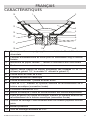
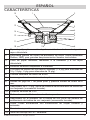
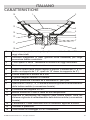
CARACTÉRISTIQUES
13
12
15
14
11
10 9
1 2
3
6
5
7
4
8
CC
1 Cache-poussière en polypropylène — résiste à l'humidité et aux
ultraviolets
2 Panneau surdimensionné en nitrile pour un mouvement long à contrôle
linéaire
3 Membrane de papier ventilée — résiste à l'humidité et aux ultra-violets
4 Cadre sur mesure en acier matricé
5 Gabarit ventilé Kapton de bobine acoustique (les modèles 10” et 12"
utilisent le gabarit 1,5", le modèle 15” utilisent le gabarit 2")
6 Platine avant en acier de 8 mm
7 2 grands aimants en céramique
8 Platine arrière/collier T polaire en acier 8 mm
9 Évent de 0,75". Élément du système amélioré de refroidissement de la
bobine acoustique (convection forcée)
10 Protecteur d'aimant en PVC
11 Bobine acoustique 4 ohms en cuivre résistant aux hautes températures
12 Évent du gabarit de bobine acoustique. Élément du système amélioré de
refroidissement de la bobine acoustique (convection forcée)
13 Anneau de centrage Conex entrelacé avec fils rosettes piqués et bouclés
joints
14 Bornes-poussoirs
15 Joint de montage réversible en PVC

18 © 2007 directed electronics—all rights reserved
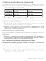
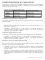
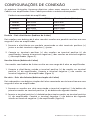
CONFIGURATIONS DE CÂBLAGE
Les illustrations suivantes fournissent des indications sur le câblage correct de votre
haut-parleur Orion Cobalt à un amplificateur Orion Cobalt pour un rendement optimal.
Puissance d'amplificateur recommandée
Puissance continue (RMS) Puissance de crête (watts)
1 haut-parleur 100 à 300 200 à 600
2 haut-parleurs 200 à 600 400 à 1200
3 haut-parleurs 300 à 900 600 à 1800
4 haut-parleurs 400 à 1200 800 à 2400
Parallèle — Deux haut-parleurs (bobines acoustiques 4 ohms)
Deux haut-parleurs à bobine acoustique de 4 ohms en parallèle résultent en une
charge de 2 ohms pour l'amplificateur.
1. Raccordez le haut-parleur en parallèle en raccordant les deux bornes positives (+)
d'une part et les deux bornes négatives (-) d'autre part.
2. Raccordez les bornes positives (+) des haut-parleurs à la borne positive (+) de
l'amplificateur. Raccordez les bornes négatives (-) des haut-parleurs à la borne
négative (-) de l'amplificateur (figure 2).
Un haut-parleur (bobine acoustique 4 ohms)
Un haut-parleur à bobine acoustique de 4 ohms résulte en une charge de 4 ohms pour
l'amplificateur.
1. Raccordez le haut-parleur en raccordant la borne positive (+) du haut-parleur à
la borne positive (+) de l'amplificateur. Raccordez la borne négative (-) du haut-
parleur à la borne négative (-) de l'amplificateur (figure 3).
Série — Deux haut-parleurs (bobines acoustiques simples 4 ohms)
Deux haut-parleurs à bobine acoustique simple de 4 ohms en série résultent en une
charge de 8 ohms pour l'amplificateur.
1. Raccordez le haut-parleur en série en raccordant la borne négative (-) d'une
bobine à la borne positive (+) de l'autre bobine.
2. Raccordez la borne positive (+) de la première bobine à la borne positive (+) de
l'amplificateur. Raccordez la borne négative (-) de la seconde bobine à la borne
négative (-) de l'amplificateur (figure 4).

© 2007 directed electronics—all rights reserved 19
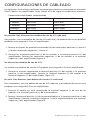
Série/parallèle — 4 haut-parleurs (bobines 4 ohms simples)
Quatre caissons de basses à bobines acoustiques simples de 4 ohms, les bobines
acoustiques de chaque paire de haut-parleurs raccordées en série et les quatre
haut-parleurs raccordés en parallèle, résultent en une charge de 4 ohms pour
l'amplificateur.
1. Raccordez la borne négative (-) du haut-parleur #1 à la borne négative du haut-
parleur #3, puis raccordez ce câble à la borne négative (-) de l'amplificateur.
2. Raccordez la borne positive (+) du haut-parleur #1 à la borne négative du haut-
parleur #2.
3. Raccordez la borne positive (+) du haut-parleur #3 à la borne négative du haut-
parleur #4.
4. Raccordez la borne positive (+) du haut-parleur #2 à la borne positive (+) du
haut-parleur #4, puis raccordez ce câble à la borne positive (+) de l'amplificateur
(figure 5).
NOTE: Diagramme de référence aux pages 4 - 7
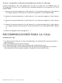
RECOMMANDATIONS SUR LES ENCEINTES
Détails des enceintes
1. Dimensions externes calculées pour des matériaux de 3/4”
2. Inclut le volume d'encombrement des haut-parleurs
3. Les volumes indiqués sont le volume d'accord net
4. Les enceintes contiennent une quantité minimale de matériaux d'amortissement. Il
suffit de prévoir assez de tissu pour le revêtement intérieur de l'enceinte.

20 © 2007 directed electronics—all rights reserved
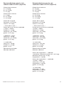
Recommandations pour l'enceinte
close Cobalt CO104S (Figure 6)
Dimensions externes
A = 14"
B = 12,5"
C = 11,5"
Dimensions internes
A = 12,5"
B = 11"
C = 10"
Épaisseur de la cloison
Avant = 0,75"
Côté = 0,75"
— Parties du boîtier —
Forme: prisme carré
1 haut, 1 bas
Profondeur (c) = 11,5"
Largeur (b) = 12,5"
Épaisseur = 0,75"
1 avant, 1 arrière
Hauteur (a) = 12,5"
Profondeur (d) = 11"
Épaisseur = 0,75"
2 côtés: Hauteur (a) = 12,5"
Profondeur (c) = 11,5"
Épaisseur = 0,75"
— Montage moteur —
Avant
Recommandations pour l'enceinte
ventilée Cobalt CO104S (Figure 7)
Dimensions externes
A = 15,75"
B = 14,25"
C = 12"
Dimensions internes
A = 14,25"
B = 12,75"
C = 10,5"
Épaisseur de la cloison
Avant = 0,75"
Côté = 0,75"
— Parties du boîtier —
Forme: prisme carré
1 haut, 1 bas:
Profondeur (c) = 12"
Largeur (b) = 14,25"
Épaisseur = 0,75"
1 avant, 1 arrière:
Hauteur (a) = 14,25"
Profondeur (d) = 12,75"
Épaisseur = 0,75"
2 côtés:
Hauteur (a) = 14,25"
Profondeur (c) = 12"
Épaisseur = 0,75"
— Montage moteur —
Avant
Pièces d'évent — rond
1 conduit: diamètre extérieur (e) = 3,25"
Diamètre intérieur (g) = 3"
Longueur (h) = 9,5"
Pièces d'évent — carré
1 haut, 1 bas:
Largeur (e) = 3"
Longueur (h) = 10"
Épaisseur = 0,125"
2 côtés:
Hauteur (g) = 2,75"
Longueur (h) = 10"
Épaisseur = 0,125"
NOTE: Diagramme de référence aux pages 8 - 13
A página está carregando...
A página está carregando...
A página está carregando...
A página está carregando...
A página está carregando...
A página está carregando...
A página está carregando...
A página está carregando...
A página está carregando...
A página está carregando...
A página está carregando...
A página está carregando...
A página está carregando...
A página está carregando...
A página está carregando...
A página está carregando...
A página está carregando...
A página está carregando...
A página está carregando...
A página está carregando...
A página está carregando...
A página está carregando...
A página está carregando...
A página está carregando...
A página está carregando...
A página está carregando...
A página está carregando...
A página está carregando...
A página está carregando...
A página está carregando...
A página está carregando...
A página está carregando...
-
 1
1
-
 2
2
-
 3
3
-
 4
4
-
 5
5
-
 6
6
-
 7
7
-
 8
8
-
 9
9
-
 10
10
-
 11
11
-
 12
12
-
 13
13
-
 14
14
-
 15
15
-
 16
16
-
 17
17
-
 18
18
-
 19
19
-
 20
20
-
 21
21
-
 22
22
-
 23
23
-
 24
24
-
 25
25
-
 26
26
-
 27
27
-
 28
28
-
 29
29
-
 30
30
-
 31
31
-
 32
32
-
 33
33
-
 34
34
-
 35
35
-
 36
36
-
 37
37
-
 38
38
-
 39
39
-
 40
40
-
 41
41
-
 42
42
-
 43
43
-
 44
44
-
 45
45
-
 46
46
-
 47
47
-
 48
48
-
 49
49
-
 50
50
-
 51
51
-
 52
52


Orion Car Audio CO154S Manual do usuário
- Tipo
- Manual do usuário
- Este manual também é adequado para
em outras línguas
- English: Orion Car Audio CO154S User manual
Artigos relacionados
Outros documentos
-
Orion CO154S Ficha de dados
-
-
-
-
-
-
Kicker del subwoofer Solo-Baric L7 Manual do proprietário
-
Philips CSP610/55 Product Datasheet
-
Sony XS-HS6 Manual do usuário
-
 Learning Resources LER 3209 Manual do usuário
