

1
ENGLISH
ENGLISH
B
B
E
E
F
F
A
A
D
D
C
C
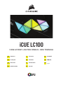
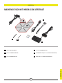
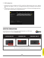
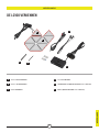
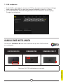
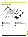
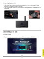
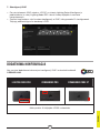
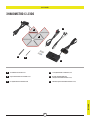
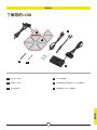
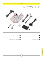
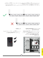
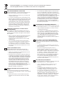
1x MASTER LC100 TRIANGLE
8x COMPANION LC100 TRIANGLES
8x 4mm CONNECTION RODS
2x 5.5mm CONNECTION RODS
LIGHTING NODE PRO (INCLUDED WITH LC100 STARTER KIT)
CABLES (INCLUDED WITH LC100 STARTER KIT)
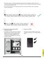
GETTING TO KNOW YOUR LC100

2
ENGLISH
A
C
B
D
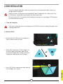
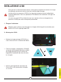
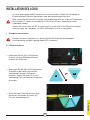
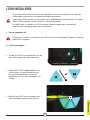
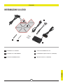
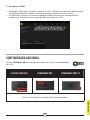
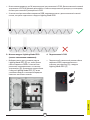
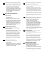
1. Turn off computer
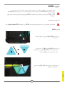
2. Mount LC100
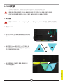
LC100 INSTALLATION
Turn your system off prior to installing your LC100 Case Accent Lighting Triangles and
Lighting Node PRO.
To ensure proper operation, keep the contact pins and connection rods free of any
foreign objects/materials.
Please use the LC100 panels and connection rods as defined in this document. Only
LC100 panels should be connected to the connection rods.
Ensure that the PC is turned off when adding, removing, or re-arranging LC100 panels
to avoid premature failure.
> Mount the [A] LC100 master triangle on a
steel surface inside the case.
> Attach [B] companion LC100 triangles to
the left or right connection sides of the
[A] master triangle by inserting a [C] 4mm
connection rod between the triangles.
> Use a [D] 5.5mm connection rod if placing
two triangles on a corner.

3
ENGLISH
A A
AA
E
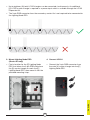
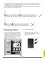
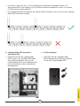
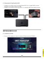
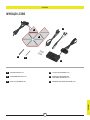
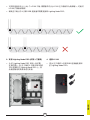
> Up to eighteen (18) total LC100 triangles can be connected simultaneously. An additional
[A] LC100 master triangle is required as a power input which is available through the LC100
Expansion Kit.
> The 3-pin RGB connector from the secondary master tile is not required to be connected to
the Lighting Node PRO.
3. Mount Lighting Node PRO
(Starter Kit only)
> Find a location for the [E] Lighting Node
PRO that allows the 3-pin RGB cable from
the [A] master triangle to reach the [E]
Lighting Node PRO, then mount it with the
provided mounting strips.
4. Connect LC100
> Connect the 3-pin RGB connector from
the main [A] master triangle into the [E]
Lighting Node PRO.

4
ENGLISH
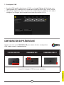
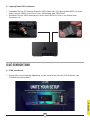
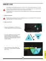
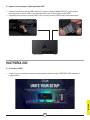
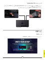
5. Connect Lighting Node PRO
> Plug the 9-pin USB cable [F] from the [E] Lighting Node PRO into an available internal USB
2.0 header on your motherboard or USB hub.
> Connect the SATA power connector to an available SATA connector from your power
supply unit.
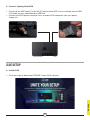
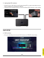
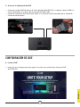
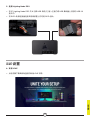
6. Install iCUE
> Click the image to download CORSAIR’s latest iCUE software.
iCUE SETUP

ENGLISH
5
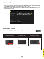
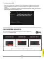
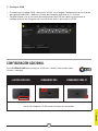
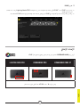
7. Configure iCUE
> Once iCUE is installed, select the “LC100” in the Lighting Setup page under Lighting Node
PRO and define the number of triangles you have in your system.
> Alternatively, use the Setup Wizard in iCUE to guide you with configuring your LC100 Case
Accent Lighting Triangles.
Please visit our CORSAIR LAB for additional iCUE setup, configuration, and tips.
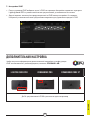
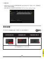
ADDITIONAL SETUP
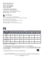
LIGHTING NODE PRO COMMANDER PRO COMMANDER CORE XT
Up to 18 LC100 triangles max. per controller

1
FRANÇAIS
FRANÇAIS
B
B
E
E
F
F
A
A
D
D
C
C
1x TRIANGLE PRINCIPAL LC100
8x TRIANGLES COMPAGNONS LC100
8x BAGUETTES DE CONNEXION 4mm
2x BAGUETTES DE CONNEXION 5,5mm
LIGHTING NODE PRO
(INCLUS DANS LE KIT DE DÉMARRAGE LC100)
CÂBLES (INCLUS DANS LE KIT DE DÉMARRAGE LC100)
PRÉSENTATION DU LC100

2
FRANÇAIS
D
A
C
B
1. Éteignez l’ordinateur
2. Montage de LC100
INSTALLATION DE LC100
Éteignez votre système avant d’installer les triangles d’éclairage d’accentuation pour
boîtier LC100 et le Lighting Node PRO.
> Montez le triangle principal LC100 [A] sur
une surface en acier à l’intérieur du boîtier.
> Fixez les triangles compagnons LC100 [B]
aux parois de connexion gauche ou droite
du triangle principal [A] en insérant une
baguette de connexion de 4mm [C] entre
les triangles.
> Utilisez une baguette de connexion de
5,5mm [D] si vous placez deux triangles
sur un coin.
Pour garantir un fonctionnement correct, évitez que les broches de contact et les tiges
de connexion entrent en contact avec tout matériau/objet étranger.
Veuillez utiliser les panneaux LC100 et les tiges de connexion comme indiqué dans
le présent document. Seuls les panneaux LC100 doivent être connectés aux tiges de
connexion.
Assurez-vous que le PC est éteint lorsque vous ajoutez, retirez ou réorganisez les
panneaux LC100 pour éviter toute panne prématurée.

3
FRANÇAIS
A A
AA
E
> Vous pouvez connecter simultanément jusqu’à dix-huit (18) triangles LC100 au total. Un
triangle principal LC100 [A] supplémentaire est requis en tant qu’entrée d’alimentation, qui
est disponible dans le kit d’extension LC100.
> Le connecteur RGB à 3broches de la deuxième vignette principale n’est pas nécessaire
pour la connexion au Lighting Node PRO.
3. Montage du Lighting Node PRO
(kit de démarrage uniquement)
> Trouvez un emplacement suffisamment
spacieux pour le Lighting Node PRO [E]
pour que le câble RGB à trois broches du
triangle principal [A] atteigne le Lighting
Node PRO [E], puis installez-le avec les
bandes de fixation fournies.
4. Connexion de LC100
> Raccordez le connecteur RGB à
3broches du triangle principal [A] au
Lighting Node PRO [E].

4
FRANÇAIS
5. Connexion de Lighting Node PRO
> Branchez le [F] câble USB à 9 broches du [E] Lighting Node PRO sur un connecteur USB
2.0 interne disponible de votre carte mère ou concentrateur USB.
> Raccordez le connecteur d’alimentation SATA à un connecteur SATA disponible de votre
unité d’alimentation.
6. Installez iCUE
> Cliquez sur l’image pour télécharger la dernière version du logiciel iCUE de CORSAIR.
CONFIGURATION iCUE

FRANÇAIS
5
7. Configurez iCUE
> Une fois iCUE installé, sélectionnez «LC100» sur la page Réglage de l’éclairage sous
Lighting Node PRO et définissez le nombre de triangles présents dans votre système.
> Vous pouvez également utiliser l’assistant de configuration dans iCUE qui vous aider à
configurer les triangles d’éclairage d’accentuation pour boîtier LC100.
Veuillez consulter notre CORSAIR LAB pour obtenir d’autres configurations
iCUE et des conseils supplémentaires.
CONFIGURATION SUPPLÉMENTAIRE
LIGHTING NODE PRO COMMANDER PRO COMMANDER CORE XT
Jusqu’à 18 triangles LC100 max. par contrôleur

1
DEUTSCH
DEUTSCH
B
B
E
E
F
F
A
A
D
D
C
C
1x LC100 MASTER-DREIECK
8x LC100 COMPANION-DREIECKE
8x 4-mm-VERBINDUNGSSTIFT
2x 5,5-mm-VERBINDUNGSSTIFT
LIGHTING NODE PRO (IM LC100 STARTER-KIT INBEGRIFFEN)
KABEL (IM LC100 STARTER-KIT INBEGRIFFEN)
MACHEN SIE SICH MIT IHREM LC100 VERTRAUT

2
DEUTSCH
D
A
C
B
1. Computer ausschalten
2. LC100 montieren
INSTALLATION DES LC100
Schalten Sie Ihren Computer aus, bevor Sie die LC100 Gehäuse betonenden
Leuchtdreiecke und den Lighting Node PRO installieren.
> Montieren Sie das [A] LC100 Master-
Dreieck auf einer Stahloberfläche im
Inneren des Gehäuses.
> Befestigen Sie die [B] LC100 Companion-
Dreiecke an der linken und rechten
Verbindungsseite des [A] Master-
Dreiecks, indem Sie einen [C] 4-mm-
Verbindungsstift zwischen den Dreiecken
einsetzen.
> Wenn Sie zwei Dreiecke an einer Ecke
platzieren, verwenden Sie einen [D]
5,5-mm-Verbindungsstift.
Um eine ordnungsgemäße Funktionsweise sicherzustellen, halten Sie Fremdkörper/
Fremdmaterialien von den Kontaktpins und den Verbindungsstiften fern.
Bitte verwenden Sie die LC100Panels und Verbindungsstifte wie in diesem Dokument
beschrieben. Es sollten ausschließlich LC100Panels mit den Verbindungsstiften
verbunden werden.
Stellen Sie sicher, dass der PC ausgeschaltet ist, wenn Sie LC100Panels hinzufügen,
entfernen oder neu anordnen, um einen frühzeitigen Ausfall zu vermeiden.

3
DEUTSCH
A A
AA
E
> Es können insgesamt bis zu 18LC100 Dreiecke miteinander verbunden werden. Zur
Stromaufnahme ist ein weiteres [A] LC100 Master-Dreieck erforderlich. Dieses ist mit dem
LC100 Erweiterungskit erhältlich.
> Der 3-polige RGB-Steckverbinder des zweiten Master-Dreiecks muss nicht mit dem Lighting
Node PRO verbunden werden.
3. Lighting Node PRO montieren
(nur Starter Kit)
> Platzieren Sie den [E] Lighting Node
PRO so, dass das 3-polige RGB-Kabel
des [A] Master-Dreiecks bis zum [E]
Lighting Node PRO reicht. Montieren Sie
ihn anschließend mit der mitgelieferten
Montageleiste.
4. LC100 verbinden
> Verbinden Sie den 3-poligen RGB-
Steckverbinder des [A] Master-Dreiecks
mit dem [E] Lighting Node PRO.

4
DEUTSCH
5. Lighting Node PRO verbinden
> Verbinden Sie das [F] 9-polige Ende des USB-Kabels des [E] Lighting Node PRO mit einem
freien internen USB-2.0-Anschluss Ihres Mainboards oder USB-Hubs.
> Schließen Sie das SATA-Netzkabel an einen freien SATA-Anschluss am Netzteil Ihres
Computers an.
6. iCUE installieren
> Klicken Sie auf die folgende Abbildung, um die neueste Version der iCUE-Software von
CORSAIR herunterzuladen.
iCUE-EINRICHTUNG

5
DEUTSCH
7. iCUE konfigurieren
> Wählen Sie nach der Installation von iCUE auf der Seite „Beleuchtungssetup“ unter „Lighting
Node PRO“ die Option „LC100“ aus, und legen Sie die Anzahl an Dreiecken in Ihrem System
fest.
> Lassen Sie sich alternativ vom Einrichtungsassistenten in iCUE durch die Konfiguration Ihrer
LC100 Gehäuse betonenden Leuchtdreiecke führen.
Informationen zur weiteren Einrichtung und Konfiguration von iCUE sowie
Tipps finden Sie in unserem CORSAIR LAB.
WEITERE EINRICHTUNG
LIGHTING NODE PRO COMMANDER PRO COMMANDER CORE XT
Bis zu 18LC100 Dreiecke pro Controller

1
NEDERLANDS
NEDERLANDS
B E
F
A D
C
1x LC100-MASTERDRIEHOEK
8x LC100-HULPDRIEHOEKEN
8x 4mm VERBINDERS
2x 5,5mm VERBINDERS
LIGHTING NODE PRO (MEEGELEVERD MET LC100-STARTSET)
KABELS (MEEGELEVERD MET LC100-STARTSET)
B
E
F
A
DC
DE LC100 VERKENNEN

2
NEDERLANDS
D
A
C
B
1. Zet de computer uit
2. LC100 bevestigen
LC100 INSTALLEREN
Schakel het systeem uit voordat je de LC100 Case Accent Lighting Triangles en Lighting
Node PRO installeert.
> Zet de [A] LC100-masterdriehoek vast op
een stalen oppervlak in de behuizing.
> Koppel [B] LC100-hulpdriehoeken vast
aan de linker- of rechterzijden van de
[A] masterdriehoek door tussen de
driehoeken een [C] 4mm verbinder in te
voegen.
> Gebruik een [D] 5,5mm verbinder als je
twee driehoeken op een hoek plaatst.
Zorg ervoor dat de contactpennen en verbinders niet in contact komen met vreemde
voorwerpen/materiaal om een goede werking te garanderen.
Gebruik de LC100-panelen en verbinders zoals gedefinieerd in dit document. Er mogen
alleen LC100-panelen met de verbinders worden verbonden.
Schakel de pc uit voordat er LC100-panelen worden toegevoegd, verwijderd of
verplaatst om voortijdige defecten te voorkomen.

3
NEDERLANDS
A A
AA
E
> Gelijktijdig kunnen maximaal achttien (18) LC100-driehoeken worden verbonden. Een extra
[A] LC100-masterdriehoek is nodig als stroominvoer. Deze is verkrijgbaar in de LC100-
uitbreidingsset.
> De 3-pins RGB-connector van de secondaire mastertegel hoeft niet te worden verbonden
met de Lighting Node PRO.
3. Lighting Node PRO bevestigen
(alleen startset)
> Zoek een plek voor de [E] Lighting Node
PRO van waaruit de 3-pins RGB-kabel
van de [A] masterdriehoek de [E] Lighting
Node PRO kan bereiken. Zet de Lighting
Node PRO vervolgens vast met de
meegeleverde bevestigingstrips.
4. LC100 verbinden
> Verbindt de 3-pins RGB-connector van
de [A] masterdriehoek met de [E] Lighting
Node PRO.

4
NEDERLANDS
5. Lighting Node PRO verbinden
> Sluit de [F] 9-pins USB-kabel van de [E] Lighting Node PRO aan op een beschikbare interne
USB 2.0-header op je moederbord of USB-hub.
> Verbindt de SATA-voedingsconnector met een beschikbare SATA-connector van de voeding.
6. iCUE installeren
> Klik op de afbeelding om de nieuwste iCUE-software van CORSAIR te downloaden.
iCUE-SETUP
A página está carregando...
A página está carregando...
A página está carregando...
A página está carregando...
A página está carregando...
A página está carregando...
A página está carregando...
A página está carregando...
A página está carregando...
A página está carregando...
A página está carregando...
A página está carregando...
A página está carregando...
A página está carregando...
A página está carregando...
A página está carregando...
A página está carregando...
A página está carregando...
A página está carregando...
A página está carregando...
A página está carregando...
A página está carregando...
A página está carregando...
A página está carregando...
A página está carregando...
A página está carregando...
A página está carregando...
A página está carregando...
A página está carregando...
A página está carregando...
A página está carregando...
A página está carregando...
A página está carregando...
A página está carregando...
A página está carregando...
A página está carregando...
A página está carregando...
A página está carregando...
A página está carregando...
A página está carregando...
A página está carregando...
-
 1
1
-
 2
2
-
 3
3
-
 4
4
-
 5
5
-
 6
6
-
 7
7
-
 8
8
-
 9
9
-
 10
10
-
 11
11
-
 12
12
-
 13
13
-
 14
14
-
 15
15
-
 16
16
-
 17
17
-
 18
18
-
 19
19
-
 20
20
-
 21
21
-
 22
22
-
 23
23
-
 24
24
-
 25
25
-
 26
26
-
 27
27
-
 28
28
-
 29
29
-
 30
30
-
 31
31
-
 32
32
-
 33
33
-
 34
34
-
 35
35
-
 36
36
-
 37
37
-
 38
38
-
 39
39
-
 40
40
-
 41
41
-
 42
42
-
 43
43
-
 44
44
-
 45
45
-
 46
46
-
 47
47
-
 48
48
-
 49
49
-
 50
50
-
 51
51
-
 52
52
-
 53
53
-
 54
54
-
 55
55
-
 56
56
-
 57
57
-
 58
58
-
 59
59
-
 60
60
-
 61
61


em outras línguas
- español: Corsair iCUE LC100 Manual de usuario
- français: Corsair iCUE LC100 Manuel utilisateur
- italiano: Corsair iCUE LC100 Manuale utente
Artigos relacionados
-
Corsair AR Series Manual do usuário
-
Corsair COMMANDER PRO Digital RGB Lighting and Fan Speed Controller Manual do usuário
-
-
-
Corsair K60 PRO TKL Guia de usuario
-
-
Corsair K65 RGB MINI Guia de usuario
-
-
-