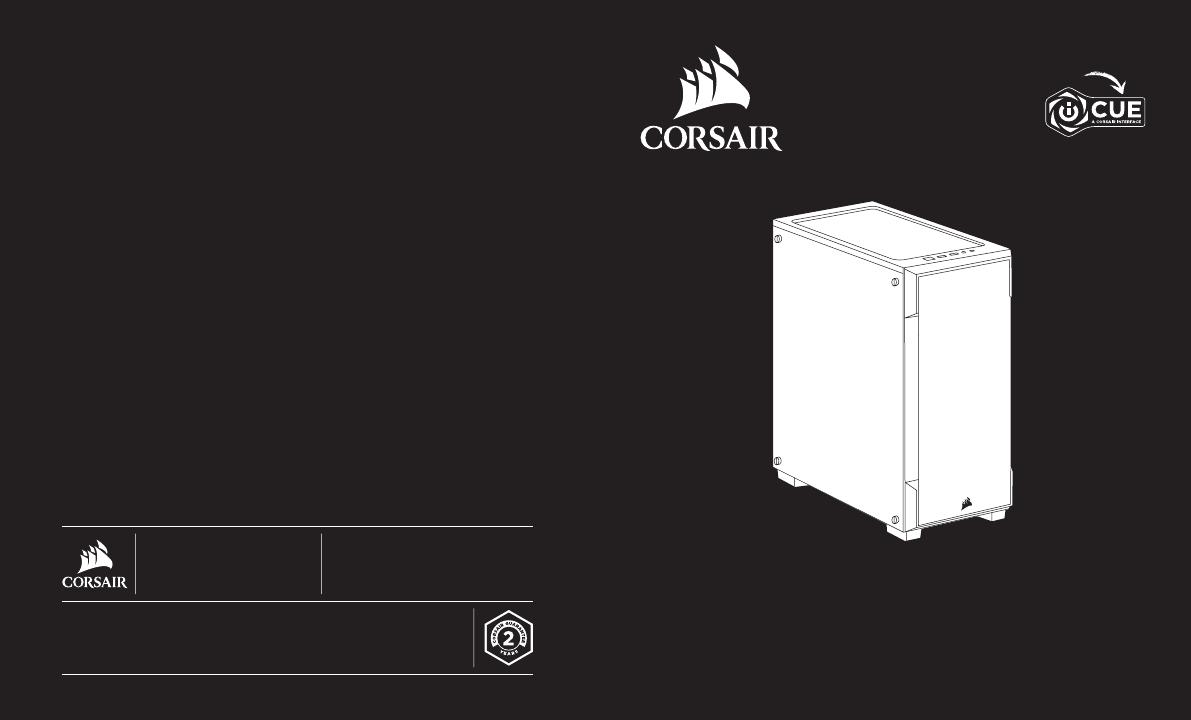
iCUE 220T RGB
Mid-Tower Gaming Case
iCUE 220T RGB
corsair.com/downloads
© 2019 CORSAIR MEMORY, Inc. All rights reserved. CORSAIR and the sails logo are
registered trademarks in the United States and/or other countries. All other trademarks
are the property of their respective owners. Product may vary slightly from those
pictured. 49-001998 AA
WEB: corsair.com
PHONE: (888) 222-4346
WARRANTY: corsair.com/support/
warranty
SUPPORT: support.corsair.com
BLOG: corsair.com/blog
FORUM: forum.corsair.com
YOUTUBE: youtube.com/corsairhowto

ENGLISH .......................................................1
FRANÇAIS ...................................................11
DEUTSCH ...................................................21
NEDERLANDS ............................................31
ITALIANO .....................................................41
ESPAÑOL ....................................................51
PORTUGUÊS ..............................................61
POLSKI ........................................................71
PУССКИЙ .....................................................81
............................................................91

1 2
ENGLISH
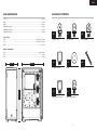
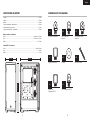
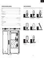
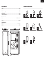
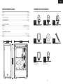
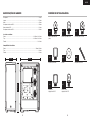
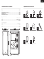
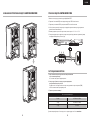
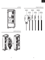
CASE SPECIFICATIONS
Length .............................................................................................................................................................398mm
Width ...............................................................................................................................................................210mm
Height ..............................................................................................................................................................450mm
Maximum GPU length .....................................................................................................................................300mm
Maximum CPU height .....................................................................................................................................160mm
Maximum PSU length......................................................................................................................................180mm
Fan locations:
Front .......................................................................................................................................3x 120mm / 2x 140mm
Top .......................................................................................................................................... 2x 120mm / 2x 140mm
Rear ............................................................................................................................................................ 1x 120mm
Radiator compatibility:
Front ................................................................................................................................................ 360mm / 280mm
Top ................................................................................................................................................................... 240mm
Rear .................................................................................................................................................................120mm
REMARK
A -ATX
M -Micro ATX
I -ITX
AM
A
M
A
M
M
AA
AMI AMI
AMIAMI
210mm 398mm
450mm
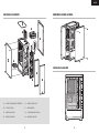
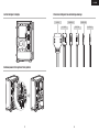
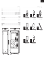
ACCESSORY KIT CONTENTS
x20
Fan screws (short)
x18
MBD / HDD screws
x12
ODD / SSD screws
x1
x1
Motherboard standoffs
Lighting Node CORE standoff
x8
x1
Washer
Lighting Node CORE screw
x12
Cable ties

3 4
ENGLISH
AM
A
A
AMI
AMIAMI
A
AM
A
MI
AMI
AM
AMI
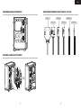
AT X
MATX
ITX
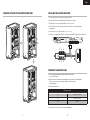
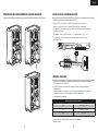
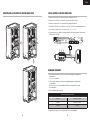
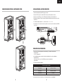
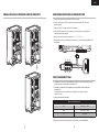
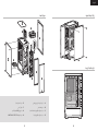
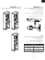
REMOVING THE SIDE PANELS
INSTALLING THE MOTHERBOARD
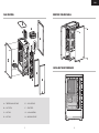
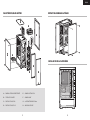
CASE FEATURES
A — TEMPERED GLASS SIDE PANEL
B — DUST FILTERS
C — SSD TRAYS
D — HDD TRAYS
E — SOLID SIDE PANEL
F — FRONT BEZEL
G — 3x 120mm RGB FANS
H — LIGHTING NODE CORE
A
B
B
E
F
C
D
H
G
B

5 6
ENGLISH
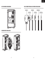
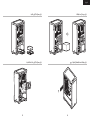
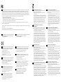
INSTALLING SSDs
INSTALLING PSUINSTALLING HDDs
INSTALLING PCI-e CARDS

7 8
ENGLISH
REMARK
A -ATX
M -Micro ATX
I -ITX
AM
A
M
A
M
M
AA
AMI AMI
AMIAMI
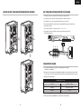
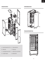
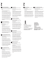
USB 3.0
HD AUDIO
RESET SW
POWER LED +
POWER LED –
POWER SW
REMOVING THE FRONT BEZEL
MOVING HDD CAGE
INSTALLING THE FRONT I/O CONNECTORS

9 10
ENGLISH
INSTALLING THE LIGHTING NODE CORE
FREQUENTLY ASKED QUESTIONS
1. Does the polarity matter with the I/O panel’s power and reset header?
No, only the LED headers.
2. Who should I contact if I received my case damaged or one of the fans is no longer working?
Please go to support.corsair.com and request an RMA so that we can replace
the damaged part(s).
3. Where can I mount a fan?
To learn more about this case visit the product page at corsair.com.
Fan mount locations
Front 3x 120mm / 2x 140mm
Top 2x 120mm / 2x 140mm
Rear 1x 120mm
1. Turn your system off prior to installing your Lighting Node CORE.
2. Plug the 9-pin USB into an available internal USB 2.0 header in your system.
3. Plug the SATA connector into an available SATA connector on your PSU.
4. The Fan LED wiring must be connected to the fan hub in the order you want the lighting effects
to be displayed.
5. Fans must start at “1” and continue in series. 1 > 2 > 3 > 4 > 5 > 6
6. Any fan not connected in series will break communication and the RGB LED lighting function will not work.
CHANGING LOCATION OF THE LIGHTING NODE CORE
1 2 3
6 5 4
1 2 3
6 5 4
2
5
3

11 12
FRANÇAIS
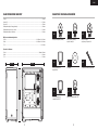
REMARK
A -ATX
M -Micro ATX
I -ITX
AM
A
M
A
M
M
AA
AMI AMI
AMIAMI
210mm 398 mm
450mm
SPÉCIFICATIONS DU BOÎTIER
Longueur .........................................................................................................................................................398mm
Largeur ............................................................................................................................................................210mm
Hauteur ............................................................................................................................................................450mm
Longueur maximale de carte graphique..........................................................................................................300mm
Hauteur maximale du processeur ...................................................................................................................160mm
Longueur maximale du bloc d’alimentation ....................................................................................................180mm
Emplacements des ventilateurs:
Avant ......................................................................................................................................3x 120mm / 2x 140mm
Haut ........................................................................................................................................2x 120mm / 2x 140mm
Arrière .........................................................................................................................................................1x 120mm
Compatibilité des radiateurs:
Avant ............................................................................................................................................... 360mm / 280mm
Haut .................................................................................................................................................................240mm
Arrière ..............................................................................................................................................................120mm
CONTENU DU KIT D’ACCESSOIRES
x20
Vis courtes pour ventilateur
x18
Vis pour carte mère /
disque dur
x12
Vis pour lecteur optique /
disque SSD
x1
Support pour carte mère
x8
Rondelles
x12
Attaches pour câbles
x1
Support pour
Lighting Node CORE
x1
Vis pour Lighting Node CORE

13 14
FRANÇAIS
AM
A
A
AMI
AMIAMI
A
AM
A
MI
AMI
AM
AMI
AT X
MATX
ITX
RETRAIT DES PANNEAUX LATÉRAUX
INSTALLATION DE LA CARTE MÈRE
CARACTÉRISTIQUES DU BOÎTIER
A — PANNEAU LATÉRAL EN VERRE TREMPÉ
B — FILTRE ANTI-POUSSIÈRE
C — PLATEAUX DE DISQUE SSD
D — PLATEAUX DE DISQUE DUR
E — PANNEAU LATÉRAL PLEIN
F — PANNEAU AVANT
G — 3x VENTILATEUR RGB DE 120mm
H — LIGHTING NODE CORE
A
B
B
E
F
C
D
H
G
B

15 16
FRANÇAIS
INSTALLATION DE SSD
INSTALLATION DU BLOC D’ALIMENTATION
INSTALLATION DES CARTES PCI-e
INSTALLATION DES DISQUES DURS

17 18
FRANÇAIS
USB 3.0
HD AUDIO
RESET SW
POWER LED +
POWER LED –
POWER SW
REMARK
A -ATX
M -Micro ATX
I -ITX
AM
A
M
A
M
M
AA
AMI AMI
AMIAMI
RETRAIT DU PANNEAU AVANT INSTALLATION DES CONNECTEURS E/S AVANT
BAIE DE DISQUE DUR AMOVIBLE

19 20
FRANÇAIS
1. La polarité est-elle importante pour l’alimentation du panneau d’E/S et le cavalier de réinitialisation?
Non, uniquement pour les cavaliers à LED.
2. À qui dois-je m’adresser si mon boîtier est endommagé à l’arrivée ou lorsqu’un ventilateur ne
fonctionne plus?
Veuillez vous rendre sur le site support.corsair.com et demandez une RMA (autorisation de retour de
marchandise) pour que nous puissions remplacer la ou les pièces endommagées.
3. Où puis-je monter un ventilateur?
Pour en savoir plus sur ce boîtier, veuillez vous rendre sur le site corsair.com,
à la page des produits.
Emplacements des fixations de ventilateur
Avant 3x 120mm / 2x 140mm
Haut 2x 120mm / 2x 140mm
Arrière 1x 120mm
INSTALLATION DU LIGHTING NODE CORE
1. Éteignez votre système avant d’installer le Lighting Node CORE.
2. Branchez l’USB à 9broches sur un cavalier USB 2.0 interne disponible sur votre système.
3. Branchez le connecteurSATA dans un connecteurSATA disponible sur votre alimentation.
4. Les câbles des LED du ventilateur doivent être connectés au hub de ventilation en respectant l’ordre
des effets lumineux voulus.
5. Les ventilateurs doivent commencer à la position «1» et continuer en série. 1 > 2 > 3 > 4 > 5 > 6
6. Un ventilateur non connecté en série entraînera l’arrêt de la communication et de la fonction
d’éclairage LED RGB.
FOIRE AUX QUESTIONS
MODIFICATION DE L’EMPLACEMENT DU LIGHTING NODE CORE
1 2 3
6 5 4
1 2 3
6 5 4
2
5
3

21 22
DEUTSCH
REMARK
A -ATX
M -Micro ATX
I -ITX
AM
A
M
A
M
M
AA
AMI AMI
AMIAMI
210mm 398mm
450mm
TECHNISCHE DATEN DES GEHÄUSES
Länge ...............................................................................................................................................................398mm
Breite ...............................................................................................................................................................210mm
Höhe ................................................................................................................................................................450mm
Maximale GPU-Länge .....................................................................................................................................300mm
Maximale CPU-Höhe .......................................................................................................................................160mm
Maximale Netzteil-Länge .................................................................................................................................180mm
Lüfterpositionen:
Vorderseite..............................................................................................................................3x 120mm / 2x 140mm
Oben .......................................................................................................................................2x 120mm / 2x 140mm
Rückseite .................................................................................................................................................... 1x 120mm
Radiatorkompatibilität:
Vorderseite....................................................................................................................................... 360mm / 280mm
Oben ................................................................................................................................................................240mm
Rückseite .........................................................................................................................................................120mm
INHALT DES ZUBEHÖRKITS
x20
Kurze Schrauben für Lüfter
x18
Schrauben für die Hauptplatine
und Festplattenlaufwerke
x12
Schrauben für optische und
SSD-Laufwerke
x1
Abstandhalter für hauptplatine
x8
Unterlegscheiben
x12
Kabelbinder
x1
Abstandhalter für
Lighting Node CORE
x1
Lighting Node CORE-Schrauben

23 24
DEUTSCH
ABNEHMEN DER SEITENPLATTEN
INSTALLATION DES MOTHERBOARDS
FUNKTIONSMERKMALE DES GEHÄUSES
A — SEITENABDECKUNG AUS
GEHÄRTETEM GLAS
B — STAUBFILTER
C — SSD-SCHÄCHTE
D — HDD-SCHÄCHTE
E — MASSIVE SEITENABDECKUNG
F — BLENDE VORDERSEITE
G — 3 × RGB-LÜFTER, 120mm
H — LIGHTING NODE CORE
AM
A
A
AMI
AMIAMI
A
AM
A
MI
AMI
AM
AMI
AT X
MATX
ITX
A
B
B
E
F
C
D
H
G
B

25 26
DEUTSCH
INSTALLATION VON SSD-LAUFWERK
INSTALLATION DES NETZTEILS (PSU)
INSTALLIEREN VON PCI-e-KARTEN
INSTALLATION VON HDD-LAUFWERKEN

27 28
DEUTSCH
USB 3.0
HD AUDIO
RESET SW
POWER LED +
POWER LED –
POWER SW
REMARK
A -ATX
M -Micro ATX
I -ITX
AM
A
M
A
M
M
AA
AMI AMI
AMIAMI
ABNEHMEN DER VORDEREN BLENDE INSTALLATION DER VORDEREN I/O -ANSCHLÜSSE
ABNEHMBARER FESTPLATTENKÄFIG

29 30
DEUTSCH
1. Muss bei der Ein/Austaste und dem Rücksetzschalter der I/O-Abdeckung die Polarität beachtet werden?
Nein, nur bei den LED-Headern.
2. An wen kann ich mich wenden, wenn ich ein beschädigtes Gehäuse erhalten habe oder einer der Lüfter
nicht mehr funktioniert?
Gehen Sie zu support.corsair.com und fordern Sie eine RMA an, damit wir die beschädigten
Teile ersetzen können.
3. Wo kann ich einen Lüfter anbringen?
Weitere Informationen über dieses Gehäuse finden Sie auf der Produktseite bei corsair.com.
HÄUFIG GESTELLTE FRAGEN
Lüfter-Einbaupunkte
Vorderseite 3x 120mm / 2x 140mm
Oberseite 2x 120mm / 2x 140mm
Rückseite 1x 120mm
INSTALLATION DES LIGHTING NODE CORE
1. Schalten Sie Ihren Computer aus, bevor Sie den Lighting Node CORE installieren.
2. Verbinden Sie das 9-polige Ende des USB-Kabels mit einem freien internen USB-2.0-Anschluss
Ihres Computers.
3. Verbinden Sie den SATA-Stecker mit einem freien SATA-Anschluss Ihres Netzteils.
4. Die LED-Kabel des Lüfters müssen in der Reihenfolge an die Lüfternabe angeschlossen werden,
in der die Lichteffekte angezeigt werden sollen.
5. Die Lüfter müssen bei „1“ beginnen und in numerischer Reihenfolge angeordnet werden: 1 > 2 > 3 > 4 > 5 > 6
6. Jeder Lüfter, der nicht in der richtigen Reihenfolge angeschlossen ist, unterbricht die Kommunikation und
damit das Funktionieren der RGB-LED-Beleuchtungsfunktion.
ÄNDERN DER POSITION DES LIGHTING NODE CORE
1 2 3
6 5 4
1 2 3
6 5 4
2
5
3

31 32
NEDERLANDS
SPECIFICATIES BEHUIZING
Lengte..............................................................................................................................................................398mm
Breedte ............................................................................................................................................................210mm
Hoogte .............................................................................................................................................................450mm
Maximale GPU-lengte .....................................................................................................................................300mm
Maximale CPU-hoogte ....................................................................................................................................160mm
Maximale PSU-lengte ......................................................................................................................................180mm
Fanlocaties:
Voorzijde .................................................................................................................................3x 120mm / 2x 140mm
Bovenzijde ..............................................................................................................................2x 120mm / 2x 140mm
Achterzijde ..................................................................................................................................................1x 120mm
Radiatorcompatibiliteit:
Voorzijde .......................................................................................................................................... 360mm / 280mm
Bovenzijde .......................................................................................................................................................240mm
Achterzijde .......................................................................................................................................................120mm
REMARK
A -ATX
M -Micro ATX
I -ITX
AM
A
M
A
M
M
AA
AMI AMI
AMIAMI
210mm 398mm
450mm
INHOUD ACCESSOIRESKIT
x20
Schroeven voor fans (kort)
x18
Schroeven voor MBD / HDD
x12
Schroeven voor ODD / SSD
x1
Afstandhouders voor moederbord
x8
Sluitring
x12
Kabelbinders
x1
Afstandhouders voor
Lighting Node CORE
x1
Schroeven voor
Lighting Node CORE

33 34
NEDERLANDS
AM
A
A
AMI
AMIAMI
A
AM
A
MI
AMI
AM
AMI
AT X
MATX
ITX
DE ZIJPANELEN VERWIJDEREN
HET MOEDERBORD INSTALLEREN
ONDERDELEN VAN DE BEHUIZING
A — ZIJPANEEL VAN GEHARD GLAS
B — STOFFILTERS
C — SSD-LADES
D — HDD-LADES
E — MASSIEF ZIJPANEEL
F — VOORPANEEL
G — 3x 120mm RGB-FANS
H — CORE-VERLICHTINGSKNOOPPUNT
A
B
B
E
F
C
D
H
G
B

35 36
NEDERLANDS
SSD’s INSTALLEREN
PSU INSTALLERENHDD’s INSTALLEREN
PCI-e-KAARTEN INSTALLEREN
A página está carregando ...
A página está carregando ...
A página está carregando ...
A página está carregando ...
A página está carregando ...
A página está carregando ...
A página está carregando ...
A página está carregando ...
A página está carregando ...
A página está carregando ...
A página está carregando ...
A página está carregando ...
A página está carregando ...
A página está carregando ...
A página está carregando ...
A página está carregando ...
A página está carregando ...
A página está carregando ...
A página está carregando ...
A página está carregando ...
A página está carregando ...
A página está carregando ...
A página está carregando ...
A página está carregando ...
A página está carregando ...
A página está carregando ...
A página está carregando ...
A página está carregando ...
A página está carregando ...
A página está carregando ...
A página está carregando ...
A página está carregando ...
A página está carregando ...
A página está carregando ...
-
 1
1
-
 2
2
-
 3
3
-
 4
4
-
 5
5
-
 6
6
-
 7
7
-
 8
8
-
 9
9
-
 10
10
-
 11
11
-
 12
12
-
 13
13
-
 14
14
-
 15
15
-
 16
16
-
 17
17
-
 18
18
-
 19
19
-
 20
20
-
 21
21
-
 22
22
-
 23
23
-
 24
24
-
 25
25
-
 26
26
-
 27
27
-
 28
28
-
 29
29
-
 30
30
-
 31
31
-
 32
32
-
 33
33
-
 34
34
-
 35
35
-
 36
36
-
 37
37
-
 38
38
-
 39
39
-
 40
40
-
 41
41
-
 42
42
-
 43
43
-
 44
44
-
 45
45
-
 46
46
-
 47
47
-
 48
48
-
 49
49
-
 50
50
-
 51
51
-
 52
52
-
 53
53
-
 54
54


Corsair iCUE 220T Manual do usuário
- Tipo
- Manual do usuário
- Este manual também é adequado para
em outros idiomas
- español: Corsair iCUE 220T Manual de usuario
- français: Corsair iCUE 220T Manuel utilisateur
- italiano: Corsair iCUE 220T Manuale utente
- English: Corsair iCUE 220T User manual
- русский: Corsair iCUE 220T Руководство пользователя
- Nederlands: Corsair iCUE 220T Handleiding
- Deutsch: Corsair iCUE 220T Benutzerhandbuch
- polski: Corsair iCUE 220T Instrukcja obsługi
Artigos relacionados
-
Corsair Carbide Series Guia de instalação
-
Corsair 4000D AIRFLOW Mid-Tower PC Case Guia de usuario
-
-
Corsair HD140 Guia rápido
-
Corsair iCUE Elite Manual do usuário
-
-
-
Corsair iCUE LC100 Manual do usuário
-
Corsair AX1500i Manual do usuário
-
Corsair AR Series Manual do usuário
Outros documentos
-
ZALMAN X7 Manual do usuário
-
ZALMAN S5 ATX Mid Tower Computer Case Manual do usuário
-
-
-
NZXT H500i Manual do usuário
-
Sharkoon VS8 Black Manual do proprietário
-
Sharkoon VS9 Black Manual do proprietário
-
-
-