
INDOOR UNITS SYSTEM FREE
RCI-(1.0-6.0)FSN3Ei / P-N23NA
INSTALLATION AND OPERATION MANUAL
MANUAL DE INSTALACIÓN Y FUNCIONAMIENTO
INSTALLATIONS- UND BETRIEBSHANDBUCH
MANUEL D’INSTALLATION ET DE FONCTIONNEMENT
MANUALE D’INSTALLAZIONE E D’USO
MANUAL DE INSTALAÇÃO E DE FUNCIONAMENTO
INSTALLATIONS- OG BETJENINGSVEJLEDNING
INSTALLATIE- EN BEDIENINGSHANDLEIDING
INSTALLATION- OCH DRIFTHANDBOK
ΕΓΧΕΙΡΙΔΙΟ ΕΓΚΑΤΑΣΤΑΣΗΣ ΚΑΙ ΛΕΙΤΟΥΡΓΙΑΣ
4 - way cassette


English
Specications in this manual are subject to change without notice in order that HITACHI may bring the latest innovations
to their customers.
Whilst every effort is made to ensure that all specications are correct, printing errors are beyond HITACHI’s control;
HITACHI cannot be held responsible for these errors.
Español
Las especicaciones de este manual están sujetas a cambios sin previo aviso a n de que HITACHI pueda ofrecer las
últimas innovaciones a sus clientes.
A pesar de que se hacen todos los esfuerzos posibles para asegurarse de que las especicaciones sean correctas, los
errores de impresión están fuera del control de HITACHI, a quien no se hará responsable de ellos.
Deutsch
Bei den technischen Angaben in diesem Handbuch sind Änderungen vorbehalten, damit HITACHI seinen Kunden die
jeweils neuesten Innovationen präsentieren kann.
Sämtliche Anstrengungen wurden unternommen, um sicherzustellen, dass alle technischen Informationen ohne Fehler
veröffentlicht worden sind. Für Druckfehler kann HITACHI jedoch keine Verantwortung übernehmen, da sie außerhalb
ihrer Kontrolle liegen.
Français
Les caractéristiques publiées dans ce manuel peuvent être modiées sans préavis, HITACHI souhaitant pouvoir toujours
offrir à ses clients les dernières innovations.
Bien que tous les efforts sont faits pour assurer l’exactitude des caractéristiques, les erreurs d’impression sont hors du
contrôle de HITACHI qui ne pourrait en être tenu responsable.
Italiano
Le speciche di questo manuale sono soggette a modica senza preavviso afnché HITACHI possa offrire ai propri
clienti le ultime novità.
Sebbene sia stata posta la massima cura nel garantire la correttezza dei dati, HITACHI non è responsabile per eventuali
errori di stampa che esulano dal proprio controllo.
Português
As especicações apresentadas neste manual estão sujeitas a alterações sem aviso prévio, de modo a que a HITACHI
possa oferecer aos seus clientes, da forma mais expedita possível, as inovações mais recentes.
Apesar de serem feitos todos os esforços para assegurar que todas as especicações apresentadas são correctas,
quaisquer erros de impressão estão fora do controlo da HITACHI, que não pode ser responsabilizada por estes erros
eventuais.
Dansk
Specikationerne i denne vejledning kan ændres uden varsel, for at HITACHI kan bringe de nyeste innovationer ud til
kunderne.
På trods af alle anstrengelser for at sikre at alle specikationerne er korrekte, har HITACHI ikke kontrol over trykfejl, og
HITACHI kan ikke holdes ansvarlig herfor.
Nederlands
De specicaties in deze handleiding kunnen worden gewijzigd zonder verdere kennisgeving zodat HITACHI zijn klanten
kan voorzien van de nieuwste innovaties.
Iedere poging wordt ondernomen om te zorgen dat alle specicaties juist zijn. Voorkomende drukfouten kunnen echter
niet door HITACHI worden gecontroleerd, waardoor HITACHI niet aansprakelijk kan worden gesteld voor deze fouten.
Svenska
Specikationerna i den här handboken kan ändras utan föregående meddelande för att HITACHI ska kunna leverera de
senaste innovationerna till kunderna.
Vi på HITACHI gör allt vi kan för att se till att alla specikationer stämmer, men vi har ingen kontroll över tryckfel och kan
därför inte hållas ansvariga för den typen av fel.
Eλλhnika
Οι προδιαγραφές του εγχειριδίου μπορούν να αλλάξουν χωρίς προειδοποίηση, προκειμένου η HITACHI να παρέχει τις
τελευταίες καινοτομίες στους πελάτες της.
Αν και έχει γίνει κάθε προσπάθεια προκειμένου να εξασφαλιστεί ότι οι προδιαγραφές είναι σωστές, η HITACHI δεν μπορεί
να ελέγξει τα τυπογραφικά λάθη και, ως εκ τούτου, δεν φέρει καμία ευθύνη για αυτά τα λάθη.

! ATTENTION
• This product shall not be mixed with general house waste at the end of its life and it shall be retired according to the ap-
propriated local or national regulations in a environmentally correct way.
• Due to the refrigerant, oil and other components contained in Air Conditioner, its dismantling must be done by a profes-
sional installer according to the applicable regulations. Contact to the corresponding authorities for more information.
! ATENCIÓN
• Éste producto no se debe eliminar con la basura doméstica al nal de su vida útil y se debe desechar de manera respetuosa con el
medio ambiente de acuerdo con los reglamentos locales o nacionales aplicables.
• Debido al refrigerante, el aceite y otros componentes contenidos en el sistema de aire acondicionado, su desmontaje debe realizarlo
un instalador profesional de acuerdo con la normativa aplicable. Para obtener más información, póngase en contacto con las autori-
dades competentes.
! ACHTUNG
• Dass Ihr Produkt am Ende seiner Betriebsdauer nicht in den allgemeinen Hausmüll geworfen werden darf, sondern entsprechend den
geltenden örtlichen und nationalen Bestimmungen auf umweltfreundliche Weise entsorgt werden muss.
• Aufgrund des Kältemittels, des Öls und anderer in der Klimaanlage enthaltener Komponenten muss die Demontage von einem
Fachmann entsprechend den geltenden Vorschriften durchgeführt werden. Für weitere Informationen setzen Sie sich bitte mit den
entsprechenden Behörden in Verbindung.
! ADVERTISSEMENT
• Ne doit pas être mélangé aux ordures ménagères ordinaires à la n de sa vie utile et qu’il doit être éliminé conformément à la régle-
mentation locale ou nationale, dans le plus strict respect de l’environnement.
• En raison du frigorigène, de l’huile et des autres composants que le climatiseur contient, son démontage doit être réalisé par un ins-
tallateur professionnel conformément aux réglementations en vigueur.
! AVVERTENZE
• Indicazioni per il corretto smaltimento del prodotto ai sensi della Direttiva Europea 2002/96/EC e Dlgs 25 luglio 2005 n.151
• Il simbolo del cassonetto barrato riportato sull’ apparecchiatura indica che il prodotto alla ne della propria vita utile deve essere rac-
colto separatamente dagli altri riuti.
• L’utente dovrà, pertanto, conferire l’apparecchiatura giunta a ne vita agli idonei centri di raccolta differenziata dei riuti elettronici ed
elettrotecnici, oppure riconsegnarla al rivenditore al momento dell’ acquisto di una nuova apparecchiatura di tipo equivalente.
• L’adeguata raccolta differenziata delle apparecchiature dismesse, per il loro avvio al riciclaggio, al trattamento ed allo smaltimento
ambientalmente compatibile, contribuisce ad evitare possibili effetti negativi sull’ ambiente e sulla salute e favorisce il riciclo dei mate-
riali di cui è composta l’ apparecchiatura.
• Non tentate di smontare il sistema o l’unità da soli poichè ciò potrebbe causare effetti dannosi sulla vostra salute o sull’ ambiente.
• Vogliate contattare l’ installatore, il rivenditore, o le autorità locali per ulteriori informazioni.
• Lo smaltimento abusivo del prodotto da parte dell’utente può comportare l’applicazione delle sanzioni amministrative di cui all’articolo
50 e seguenti del D.Lgs. n. 22/1997.
! CUIDADO
• O seu produto não deve ser misturado com os desperdícios domésticos de carácter geral no nal da sua duração e que deve ser
eliminado de acordo com os regulamentos locais ou nacionais adequados de uma forma correcta para o meio ambiente.
• Devido ao refrigerante, ao óleo e a outros componentes contidos no Ar condicionado, a desmontagem deve ser realizada por um
instalador prossional de acordo com os regulamentos aplicáveis. Contacte as autoridades correspondentes para obter mais infor-
mações.
! ADVASEL!
• At produktet ikke må smides ud sammen med almindeligt husholdningsaffald, men skal bortskaffes i overensstemmelse med de
gældende lokale eller nationale regler på en miljømæssig korrekt måde.
• Da klimaanlægget indeholder kølemiddel, olie samt andre komponenter, skal afmontering foretages af en fagmand i overensstem-
melse med de gældende bestemmelser. Kontakt de pågældende myndigheder for at få yderligere oplysninger.
! VOORZICHTIG
• Dit houdt in dat uw product niet wordt gemengd met gewoon huisvuil wanneer u het weg doet en dat het wordt gescheiden op een
milieuvriendelijke manier volgens de geldige plaatselijke en landelijke reguleringen.
• Vanwege het koelmiddel, de olie en andere onderdelen in de airconditioner moet het apparaat volgens de geldige regulering door
een professionele installateur uit elkaar gehaald worden. Neem contact op met de betreffende overheidsdienst voor meer informatie.
! FÖRSIKTIGHET
• Det innebär att produkten inte ska slängas tillsammans med vanligt hushållsavfall utan kasseras på ett miljövänligt sätt i enlighet med
gällande lokal eller nationell lagstiftning.
• Luftkonditioneringsaggregatet innehåller kylmedium, olja och andra komponenter, vilket gör att det måste demonteras av en fackman
i enlighet med tillämpliga regelverk. Ta kontakt med ansvarig myndighet om du vill ha mer information.
! ΠΡΟΣΟΧΗ
• Σημαίνει ότι το προϊόν δεν θα πρέπει να αναμιχθεί με τα διάφορα οικιακά απορρίμματα στο τέλος του κύκλου ζωής του και θα πρέπει να
αποσυρθεί σύμφωνα με τους κατάλληλους τοπικούς ή εθνικούς κανονισμούς και με τρόπο φιλικό προς το περιβάλλον.
Λόγω του ψυκτικού, του λαδιού και άλλων στοιχείων που περιέχονται στο κλιματιστικό, η αποσυναρμολόγησή του πρέπει να γίνει από
επαγγελματία τεχνικό και σύμφωνα με τους ισχύοντες κανονισμούς.
Για περισσότερες λεπτομέρειες, επικοινωνήστε με τις αντίστοιχες αρχές.

INDEX
1 GENERAL INFORMATION
2 NAME OF PARTS
3 UNITS INSTALLATION
4 REFRIGERANT PIPING
5 DRAIN PIPING
6 ELECTRICAL WIRING
7 REMOTE CONTROLLER OPERATION
8 INSTALLATION OF OPTIONAL AIR PANEL: P-N23NA
9 MAINTENANCE
ÍNDICE
1 INFORMACIÓN GENERAL
2 NOMBRES DE LAS PIEZAS
3 INSTALACIÓN DE LAS UNIDADES
4 TUBERÍA DE REFRIGERANTE
5 TUBERÍA DE DESAGÜE
6 CABLEADO ELÉCTRICO
7 FUNCIONAMIENTO DEL MANDO A DISTANCIA
8 INSTALACIÓN DEL PANEL DE AIRE OPCIONAL: P-N23NA
9 MANTENIMIENTO
INHALT
1 ALLGEMEINE INFORMATIONEN
2 TEILEBEZEICHNUNG
3 GERÄTEINSTALLATION
4 KÄLTEMITTELLEITUNGEN
5 ABFLUSSLEITUNGEN
6 KABELANSCHLUSS
7 BETRIEB MIT FERNBEDIENUNG
8 INSTALLATION EINER OPTIONALEN AUSTRITTSBLENDE:
P-N23NA
9 WARTUNG
INDEX
1 INFORMATIONS GÉNÉRALES
2 NOMENCLATURE DES PIÈCES
3 INSTALLATION DES UNITÉS
4 TUYAUTERIE FRIGORIFIQUE
5 TUYAU D'ÉVACUATION
6 CÂBLAGE ÉLECTRIQUE
7 FONCTIONNEMENT DE LA TÉLÉCOMMANDE
8 INSTALLATION DU PANNEAU DE SOUFFLAGE EN
OPTION : P-N23NA
9 MAINTENANCE
INDICE
1 INFORMAZIONI GENERALI
2 NOMENCLATURA DEI COMPONENTI
3 INSTALLAZIONE DELLE UNITÀ
4 LINEA REFRIGERANTE
5 LINEA DI DRENAGGIO
6 COLLEGAMENTO DELLO SCHEMA ELETTRICO
7 FUNZIONAMENTO DEL COMANDO REMOTO
8 INSTALLAZIONE DEL PANNELLO DI MANDATA
OPZIONALE: P-N23NA
9 MANUTENZIONE
ÍNDICE
1 INFORMAÇÃO GERAL
2 NOME DAS PEÇAS
3 INSTALAÇÃO DAS UNIDADES
4 TUBAGEM DE REFRIGERANTE
5 TUBAGEM DE DESCARGA
6 LIGAÇÕES ELÉCTRICAS
7 FUNCIONAMENTO DOS CONTROLOS REMOTOS
8 INSTALAÇÃO DO PAINEL DE AR OPCIONAL: P-N23NA
9 MANUTENÇÃO
INDEKS
1 GENEREL INFORMATION
2 NAVN PÅ DELE
3 INSTALLATION AF ENHEDER
4 RØRFØRING FOR KØLEMIDDEL
5 AFLØBSRØR
6 ELEKTRISK LEDNINGSFØRING
7 FJERNBETJENING
8 MONTERING AF VALFRIT UDLUFTNINGSPANEL: P-N23NA
9 VEDLIGEHOLDELSE
INDEX
1 ALGEMENE INFORMATIE
2 NAMEN VAN ONDERDELEN
3 INSTALLATIE VAN DE UNITS
4 KOELLEIDINGEN
5 AFVOERLEIDING
6 ELEKTRISCHE BEDRADING
7 GEBRUIK VAN DE EXTERNE BEDIENING
8 INSTALLATIE VAN OPTIONEEL LUCHTROOSTER:
P-N23NA
9 ONDERHOUD
INDEX
1 ALLMÄN INFORMATION
2 DELARNAS NAMN
3 INSTALLATION AV ENHETER
4 KYLRÖR
5 DRÄNERINGSRÖR
6 KABELANSLUTNINGAR
7 ANVÄNDA FJÄRRKONTROLLEN
8 INSTALLATION AV EXTRA PANEL: P-N23NA
9 UNDERHÅLL
ΕΥΡΕΤΗΡΙΟ
1 ΓΕΝΙΚΕΣ ΠΛΗΡΟΦΟΡΙΕΣ
2 ΟΝΟΜΑΤΑ ΕΞΑΡΤΗΜΑΤΩΝ
3 ΕΓΚΑΤΑΣΤΑΣΗ ΜΟΝΑΔΩΝ
4 ΣΩΛΗΝΩΣΕΙΣ ΨΥΚΤΙΚΟΥ
5 ΣΩΛΗΝΩΣΕΙΣ ΑΠΟΧΕΤΕΥΣΗΣ
6 ΗΛΕΚΤΡΙΚΗ ΚΑΛΩΔΙΩΣΗ
7 ΛΕΙΤΟΥΡΓΙΑ ΤΗΛΕΧΕΙΡΙΣΤΗΡΙΟΥ
8 ΕΓΚΑΤΑΣΤΑΣΗ ΠΡΟΑΙΡΕΤΙΚΟΥ ΣΤΟΜΙΟΥ ΑΕΡΑ: P-N23NA
9 ΣΥΝΤΗΡΗΣΗ
EN English Original version
ES Español Versión traducida
DE Deutsch Übersetzte Version
FR Français Version traduite
IT Italiano Versione tradotta
PT Português Versão traduzidal
DA Dansk Oversat version
NL Nederlands Vertaalde versie
SV Svenska Översatt version
EL Ελληνικα Μεταφρασμένη έκδοση


ENGLISH
1 GENERAL INFORMATION
1.1 GENERAL NOTES
No part of this publication may be reproduced, copied, led
or transmitted in any shape or form without the permission of
Johnson Controls-Hitachi Air Conditioning Spain, S.A.U.
Within the policy of continuous improvement of its products,
Johnson Controls-Hitachi Air Conditioning Spain, S.A.U.
reserves the right to make changes at any time without prior
notication and without being compelled to introducing them into
products subsequently sold. This document may therefore have
been subject to amendments during the life of the product.
HITACHI makes every effort to offer correct, up-to-date
documentation. Despite this, printing errors cannot be controlled
by HITACHI and are not its responsibility.
As a result, some of the images or data used to illustrate this
document may not refer to specic models. No claims will be
accepted based on the data, illustrations and descriptions
included in this manual.
No type of modication must be made to the equipment without
prior, written authorisation from the manufacturer.
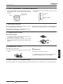
1.2 PRODUCT GUIDE
1.2.1 Prior check
? NOTE
Check, depending on the name of the model, the type of air condition-
ing system tted, the abbreviated code and reference in this instruction
manual. This Installation and Operating Manual only refers to RCI-(1.0-
6.0)FSN3Ei units.
Check, in accordance with the Installation and Operating
Manuals included with the outdoor and indoor units, that all the
information necessary for the correct installation of the system is
included. If this is not the case, please contact your distributor.
1.2.2 Classication of indoor unit models
Unit type (indoor unit): RCI
Position-separating hyphen (xed)
Capacity (HP): (1.0-6.0)
FS: SYSTEM FREE
N: R410A refrigerant
3 : Series
E : Made in Europe
i = Version up
XXX – XX FS N 3 E i
1.3 SAFETY
1.3.1 Symbols used
During normal air conditioning system design work or unit
installation, greater attention must be paid in certain situations
requiring particular care in order to avoid injuries and damage to
the unit, the installation or the building or property.
Situations that jeopardise the safety of those in the surrounding
area or that put the unit itself at risk will be clearly indicated in
this manual.
To indicate these situations, a series of special symbols will be
used to clearly identify these situations.
Pay close attention to these symbols and to the messages
following them, as your safety and that of others depends on it.
! DANGER
• The text following this symbol contains information and instruc-
tions relating directly to your safety and physical wellbeing.
• Not taking these instructions into account could lead to serious,
very serious or even fatal injuries to you and others in the prox-
imities of the unit.
In the texts following the danger symbol you can also nd
information on safe procedures during unit installation.
! CAUTION
• The text following this symbol contains information and instructions
relating directly to your safety and physical wellbeing.
• Not taking these instructions into account could lead to minor injuries
to you and others in the proximities of the unit.
• Not taking these instructions into account could lead to unit damage.
In the texts following the caution symbol you can also nd
information on safe procedures during unit installation.
? NOTE
• The text following this symbol contains information or instructions that
may be of use or that require a more thorough explanation.
• Instructions regarding inspections to be made on unit parts or sys-
tems may also be included.
General information
PMML0253A rev.5 - 08/2016
1

1.3.2 Additional information about safety
! DANGER
• HITACHI is not able to foresee all the circumstances which may
result in a potential danger.
• Do not pour water in the indoor or outdoor unit. These prod-
ucts are tted with electric components. If water comes into con-
tact with electric components, this will cause a serious electric
shock.
• Do not handle or adjust the safety devices inside the indoor and
outdoor units. The handling or adjustment of these devices may
result in serious accident.
• Do not open the service cover or access panel of the indoor and
outdoor units without disconnecting the main supply.
• In the event of re, switch off the mains, put out the re immedi-
ately and contact your service supplier.
• Check that the earth cable is correctly connected.
• Connect the unit to a circuit breaker of the specied capacity.
! CAUTION
• Refrigerant leaks may hinder respiration as the gas displaces the air
in the room.
• Fit the indoor unit, the outdoor unit, the remote control and the cable
at a minimum of 3 metres away from sources of strong radiation from
electromagnetic waves, such as medical equipment.
• Do not use sprays, such as insecticides, varnishes or enamels or any
other inammable gas within a metre of the system.
• If the circuit breaker or supply fuse of the unit comes on frequently,
stop the system and contact the service suppler.
• Do not carry out maintenance or inspection work yourself. This work
must be carried out by qualied service personnel with suitable tools
and resources for the work.
• Do not place any foreign material (branches, sticks, etc.) in the air
inlet or outlet of the unit. These units are tted with high speed fans
and contact with any object is dangerous.
• This appliance must be used only by adult and capable people, hav-
ing received the technical information or instructions to handle this
appliance properly and safely.
• Children should be supervised to ensure that they do not play with
the appliance.
? NOTE
• The air in the room should be renewed and the room ventilated every
3 or 4 hours.
• The system tter and specialist shall provide anti-leak safety in ac-
cordance with local regulations.
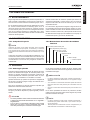
1.4 IMPORTANT NOTICE
This air conditioner has been designed for standard air
conditioning for human beings. For use in other applications,
please contact your HITACHI dealer or service contractor.
The air conditioning system should only be installed by qualied
personnel, with the necessary resources, tools and equipment,
who are familiar with the safety procedures required to
successfully carry out the installation.
The supplementary information about the purchased products
is supplied in a CD-ROM, which can be found bundled with the
outdoor unit. In case that the CD-ROM is missing or it is not
readable, please contact your HITACHI dealer or distributor.
PLEASE READ THE MANUAL AND THE FILES ON THE
CD-ROM CAREFULLY BEFORE STARTING WORK ON THE
INSTALLATION OF THE AIR CONDITIONING SYSTEM.
Failure to observe the instructions for installation,use and
operation described in this documentation may result in
operating failure including potentially serious faults, or even the
destruction of the air conditioning system.
It is assumed that the air conditioning system will be installed
and maintained by responsible personnel trained for the
purpose. If this is not the case, the customer should include all
the safety, caution and operating signs in the native language of
the personnel responsible.
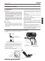
Do not install the unit in the following places, as this may lead to
a re, deformities, rusting or faults:
• Places where oil is present (including oil for machinery).
• Places with a high concentration of sulphurous gas, such as
spas.
• Places where ammable gases may be generated or
circulate.
• Places with a saline, acidic or alkaline atmosphere.
Do not install the unit in places where silicon gas is present. Any
silicon gas deposited on the surface of the heat exchanger will
repel water. As a result, the condensate water will splash out
of the collection tray and into the electrical box. Water leaks or
electrical faults may eventually be caused.
Do not install the unit in a place where the current of expelled
air directly affects animals or plants as they could be adversely
affected.
General information
PMML0253A rev.5 - 08/2016
2

ENGLISH
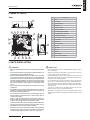
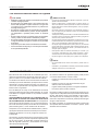
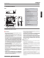
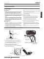
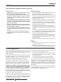
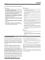
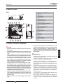
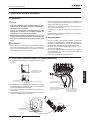
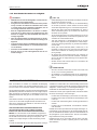
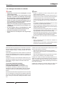
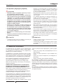
2 NAME OF PARTS
RCI
No. Part Name
1 Fan
2 Fan motor
3 Heat exchanger
4 Distributor
5 Expansion valve
6 Electric control box
7 Gas refrigerant connection
8 Liquid refrigerant connection
9 Drain pipe connection
10 Motor for drain discharge mechanism
11 Float switch
12 Drain pan
13 Panel P-N23NA
14 Air lter
15 Air outlet
16 Air inlet
17 Strainer
18 Air inlet grille
19 Cover for corner pocket
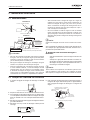
3 UNITS INSTALLATION
! DANGER
• Check to ensure that the accessories are packed with the indoor
unit.
• Do not install the indoor units outdoors. If installed outdoors, an
electric hazard or electric leakage will occur.
• Consider the air distribution from each indoor unit to the space
of the room, and select a suitable location so that uniform air
temperature in the room can be obtained. It is recommended that
the indoor units be installed 2.3 to 3 meters from the oor level. If
the unit is installed higher than 3 meters, it is also recommended
that a fan be utilised to obtain uniform air temperature in the
room.
• Avoid obstacles which may hamper the air intake or the air dis-
charge ow.
• Pay attention to the following points when the indoor units are
installed in a hospital or other places where there are electronic
waves from medical equipment, etc.
• Do not install the indoor units where electromagnetic wave is
directly radiated to the electrical box, remote control cable or
remote control switch.
• Prepare a steel box and install the remote control switch in it.
Prepare a steel conduit tube and wire the remote control cable in
it. Then connect the ground wire with the box and tube.
• Install a noise lter when the power supply emits harmful noises.
• This unit is exclusive non electrical heater type indoor unit. It is
prohibited to install a electrical heater in the eld.
• Do not put any foreign material into the indoor unit and check to
ensure that none exist in the indoor unit before the installation
and test running. Otherwise a re or failure, etc., may occur.
! CAUTION
• Do not install the indoor units in a ammable environment to avoid a
re or an explosion.
• Check to ensure that the ceiling slab is strong enough. If not strong
enough, the indoor unit may fall down on you.
• Do not install the indoor units, outdoor unit, remote control switch and
cable within approximately 3 meters of strong electromagnetic wave
radiators such as medical equipment.
• Do not install the indoor units in a machinery shop or kitchen where
vapor from oil or mist ows to the indoor units. The oil will deposit on
the heat exchanger, thereby reducing the indoor unit performance,
and may deform. In the worst case, the oil damages the plastic parts
of the indoor unit.
• To avoid any corrosive action to the heat exchangers, do not install
the indoor units in an acid or alkaline environment.
• When lifting or moving the indoor unit, use appropriate slings to avoid
damage and be careful not to damage the insulation material on units
surface.
NAME OF PARTS
PMML0253A rev.5 - 08/2016
3

3.1 INDOOR UNIT INSTALLATION
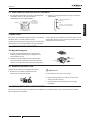
3.1.1 Factory-Supplied Accessories
Accessory Qty Purpose
Paper pattern
(Carton board)
1
For adjusting space of
false ceiling opening and
position of the unit
Cross
recessed head
screws
4 For tting paper pattern
Washer with
insulation
4
For unit installation
Washer (M10) 4
Drain hose 1
For drain hose connection
Wire clamp 2
Scale 1
For adjusting space of
false ceiling opening and
position of the unit
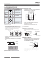
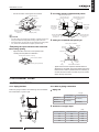
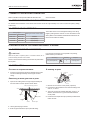
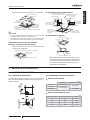
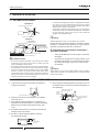
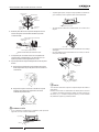
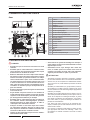
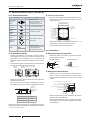
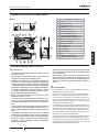
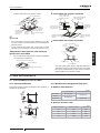
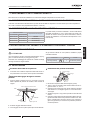
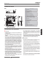
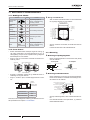
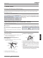
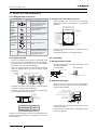
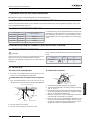
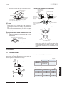
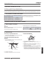
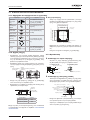
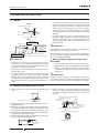
3.1.2 Initial Check
• Install the indoor unit with a proper clearance around it
paying careful attention of installation direction for the piping,
wiring and maintenance working space, as shown below.
• Provide a service access door near the unit piping
connection area on the ceiling.
Service access
door
Service
access
door
Piping connection
Drain piping connection
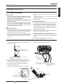
• Check space between ceiling and false ceiling is enough as
indicated below.
• Check the ceiling surface is at for the air panel installation
work.
Clearance:
10-20mm
Unit high
in false
ceiling
Unit HP A(mm)
RCI-1.0 to 2.5HP 248
RCI-3.0 to 6.0HP 298
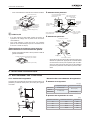
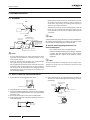
Check down slope Pitch of Drain Piping is following the
specications indicated in chapter “5 DRAIN PIPING”
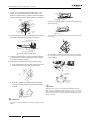
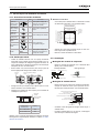
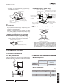
Opening Of False Ceiling
- Cut out the area for the indoor unit in the false ceiling and
install suspension bolts, as shown below:
Dimension of Opening: 860 to 910
4-Positions of
Suspension
Bolts
Optional Panel
Drain Piping
Connection Side
Piping
Connection
Side
(mm)
Dimension of Suspension
Bolts: 760
Unit size: 840
Dimension of Opening: 860 to 910
Unit size: 840
Dimension of Suspension
Bolts: 760
- Check to ensure that the ceiling is horizontally level,
otherwise water can not ow.
- Strengthen the opening parts of the false ceiling.
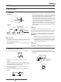
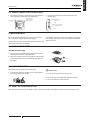
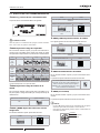
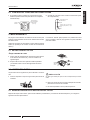
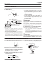
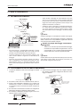
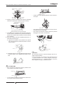
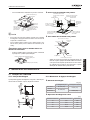
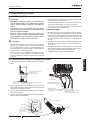
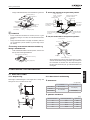
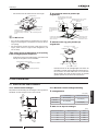
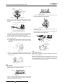
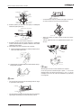
3.1.3 Installation
Mounting of suspension bolts
- Mount suspension bolts using M10 (W3/8) as size, as
shown.
For concrete slab: For steel beam:
150 to 160mm
Insert (100 to
150Kg)
Concrete
Steel
Anchor Bolt (W3/8 or M10)
Suspension Bolt (w3/8
or M10)
I-Beam
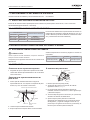
Mounting of indoor unit
- Mount the nuts and the washers to the suspension bolts.
Put the washer so that the surface with insulation can
faces downwards as shown below:
Suspension Bolts (Field-Supplied)
(mm)
Nut (Field-Supplied)
Washer with Insulation (Accessory)
Suspension Bracket (Attached Indoor Unit)
Washer (Accessory)
Nut (Field-Supplied)
Surface of Ceiling
Aprox. 52
102
Aprox. 50
- Consider piping connection side before lift indoor unit.
- Lift the indoor unit by hoist, and do not put any force on
the drain pain.
UNITS INSTALLATION
PMML0253A rev.5 - 08/2016
4

ENGLISH
- Secure the indoor unit using the nuts, washers.
Suspension bolts (4)
Suspension
bracket
False ceiling
Liquid piping
Gas piping
connection
Panel (to be installed
later, shown only as
a reference)
Drain piping
connection
Wiring hole (30x30)
Open the knockout
hole for wiring (Ø32,5)
? NOTE
• If a false ceiling has already been installed, complete all piping and
wiring work inside the ceiling before hooking-up the indoor unit.
• Secure the indoor unit using the nuts, at washers and spring wash-
ers. (These nuts and washers are supplied, 4 pieces each)
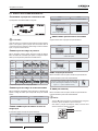
Adjusting the space between indoor units and
false ceiling opening
- Adjust the indoor unit to the correct position while
checking with the pattern for installation.
Checking scale for dimension of opening
Pattern board for installation
Packing (Corrugated board)
For ceiling already completed with panels.
Indoor unit
Attach this side of the scale
to the inner side of the
opening of the ceiling
Attach this side of the scale
to the lower side of the unit
Indoor unit
Attach this side
of the scale
to the ceiling
panel
Checking scale
Check the height of the
ceiling at each corner
of the unit
Check the dimension
of opening at each
side of the unit
Attach this side
of the scale to
the outer side of
the unit
Ceiling panel
Checking scale
Ceiling not completed with panels yet.
Pattern paper for installation
Dimension
for
opening
Unit
Suspension bolt
Surface
of
ceiling
Pattern board for installation
Screw
(M6)
Dimension
for opening
- Tighten the nuts of the suspension brackets after the
adjustment is completed. Apply LOCK-TIGHT paint to the
bolts and nuts in order to prevent them from loosening. If
not done, abnormal noises or sounds may occur and the
indoor unit may come loose.
4 REFRIGERANT PIPING
4.1 PIPING CONNECTION
4.1.1 Piping Position
Position of piping connection is the following, which is available
from all directions, top, left or right.
4.1.2 Size of piping connection
Piping size
mm (in)
Gas piping Liquid piping
RCI-1.0/1.5 Ø 12.70 (1/2)
Ø 6.35 (1/4)
RCI-2.0
Ø 15.88 (5/8)
RCI-2.5-6.0 Ø 9.52 (3/8)
Thickness of Copper Pipes
(mm)
Nominal Diameters Outer Diameters Thickness
1/4 6.35 0.80
3/8 9.52 0.80
1/2 12.70 0.80
5/8 15.88 1.00
REFRIGERANT PIPING
PMML0253A rev.5 - 08/2016
5

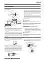
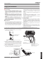
5 DRAIN PIPING
5.1 GENERAL
INCORRECT
Incorrect: Upward slope
Incorrect: Rising part
CORRECT
1/25 to 1/100
Down-slope
Min 100mm
(higher as possible)
Vynil chloride pipe (VP25)
This drain pipe
shall be separating
from other pipes
Common drain piping (min VP30)
(Down-slope from rising part)
Drain piping of unit side
! CAUTION
• Do not create an upper-slope or rise for the drain piping, since drain
water will ow back to the unit and leakage to the room will occur
when the unit operation is stopped.
• Do not connect the drain pipe with sanitary or sewage piping or any
other drainage piping.
• When the common drain piping is connected with other indoor units,
the connected position of each indoor unit must be higher than the
common piping. The pipe size of the common drain pipe must be
large enough according to the unit size and number of unit.
• Drain piping will require insulating if the drain is installed in a location
where condensation forming on the outside of drain pipe may drop
and cause damage. The insulation for the drain pipe must be selected
to insure vapor sealing and prevent condensation forming.
• Drain trap should be installed next to indoor unit. This trap must be
designed to good practice and be checked with water (charged) and
tested for correct ow. Do not tie or clamp the drain pipe and refriger-
ant pipe together.
? NOTE
Install drainage in accordance with national and local codes.
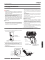
After performing drain piping work and electrical wiring, check to
ensure that water ows smoothly as in the following procedure:
Checking with Drain-Up Mechanism and Float
Switch
- Pour approximately 1.8 liters of water into the drain pan
- Check to ensure that the water ows smoothly or whether
no water leakage occurs. When water cannot be found at
the end of the drain piping, pour another approximately
1.8 liters of water into the drain pan.
? NOTE
Pay attention to the thickness of the insulation when the left side piping is
performed. If it is too thick, piping can not be installed in the unit.
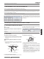
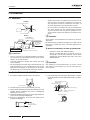
5.2 DRAIN PIPE CONNECTION
1 The position of the drain pipe connection is shown below.
Common drain piping
2 Prepare a polyvinyl chloride pipe with a 32mm outer
diameter.
3 Fasten the tubing to the drain hose with an adhesive and the
factory-supplied clamp. The drain piping must be performed
with a down-slope pitch of 1/25 to 1/100.
4 Do not apply excessive force to the drain pipe connection. It
could cause a damage.
5 Do not use a bent or twisted drain hose. It will cause water
leakage.
Gradient of Drain piping
Max.
850 mm
1/25~1/100
Down slope
6 Insulate the drain pipe after connecting the drain hose. Do
not use adhesive between the drain pipe connection and the
drain hose.
Drain pipe connection
Hose Band (Accessory)
Do not use adhesive
Vinyl Chloride VP25
(Field Supplied)
Use Vinyl Chloride type adhesive
Drain hose
(Accessory)
Hose band (Accessory)
Insulation (Field supplied)
DRAIN PIPING
PMML0253A rev.5 - 08/2016
6

ENGLISH
6 ELECTRICAL WIRING
6.1 GENERAL
! DANGER
• Turn off the main power switch to the indoor unit and the out-
door unit before electrical wiring work or a periodical check is
performed.
• Check to ensure that the indoor fan and the outdoor fan have
stopped before electrical wiring work or a periodical check is
performed.
• Protect the wires, drain pipe, electrical parts, etc. from rats or
other small animals. If not protected, rats may gnaw at unpro-
tected parts and at the worst, a re will occur.
! CAUTION
• Use twisted shielded pair cable or shield pair cable for transmission
wires between the indoor and the outdoor units, and connect the
shielded part to the earth screw in the electrical box of the indoor unit
as shown below.
• Wrap the eld supplied insulation around the wires, and plug the wir-
ing connection hole with the seal material to protect the product from
any condensate water or insects.
• Tightly secure the wires with the cord clamp inside the indoor unit.
• Lead the wires through the knockout hole in the side cover when us-
ing conduit.
• Secure the cable of the remote control switch using the cord clamp
inside the electrical box.
General Check
1 Make sure that the eld-selected electrical components
(main power switches, circuit breakers, wires, conduit
connectors and wire terminals) have been properly selected.
Make sure that the components comply with National
Electrical Code (NEC).
2 Check to ensure that the power supply voltage is within
+10% of the rated voltage.
3 Check the capacity of the electrical wires. If the power
source capacity is too low, the system cannot be started due
to the voltage drop.
4 Check to ensure that the ground wire is connected.
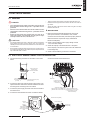
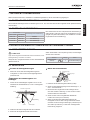
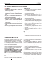
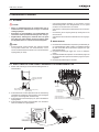
6.2 ELECTRICAL WIRING CONNECTION FOR INDOOR UNIT
1 The electrical wiring connection for the indoor unit is shown
below.
Power source wiring
operating wiring
remote control switch
cable
Hole for wiring connection Ø 32.5 (for spare)
(Knock-out hole)
Hole for wiring
connection 30x39
(for cable)
2 Connect the cable of an optional remote control switch or an
optional extension cable to the terminals inside the electrical
box through the connecting hole in the cabinet.
3 Connect the power supply and earth wires to the terminals in
the electrical box.
4 Connect the wires between the indoor unit and the outdoor
unit to the terminals in the electrical box.
Earth screw
Power source wiring
(between indoor unit
and indoor unit)
Transmission wiring
(between indoor unit and outdoor unit)
(between indoor unit and indoor unit)
Remote control switch cable
(operation wiring in case of group
control operation by using a
remote control switch)
Electrical
Box
Stopper
(Metal)
Power source wiring
Transmission wiring
Remote control switch
cable
Screw
Printed circuit
board (PCB2)
Earth
screw
Printed circuit board (PCB1)
Terminal board (TB)
ELECTRICAL WIRING
PMML0253A rev.5 - 08/2016
7

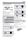
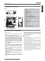
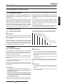
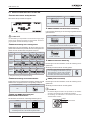
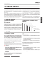
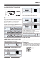
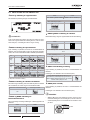
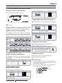
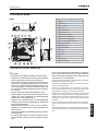
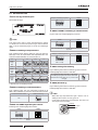
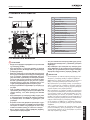
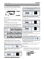
6.3 SETTINGS OF DIP SWITCHES
Quantity and Position of Dip Switches
Dips switches position is the following:
! CAUTION
Before setting dips switches, rstly turn off power source and set the po-
sition of the dips switches. If the switches are set without turning off the
power source, the contents of the setting are invalid.
DSW3: Capacity Code Setting
No setting is required, due to setting before shipment. This dip
switch is utilized for setting the capacity code which corresponds
to the horse power of the indoor unit.
HP 1.0 1.3(*) 1.5
Setting
position
ON ON ON
HP 1.8(*) 2 2.3(*) 2.5
Setting
position
ON ON ON ON
HP 3 4 5 6
Setting
position
ON ON ON ON
(*) Capacity available with DSW3 setting
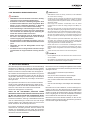
DSW4: Unit Model Code Setting
No setting is required. This switch is utilized for setting the
model code which corresponds to the indoor unit type.
Indoor unit model DSW4 setting
RCI
ON
DSW5 and RSW2: Refrigerant cycle number
setting
Setting is required. Setting position before shipment in
DSW5 RSW2
ON
Here is set DSW5 and RSW2 before shipment up to 63 can be set.
Example setting 5 system RSW2
ON
All pins are OFF
Fix to 5
DSW6 and RSW1: Unit number setting
The below gure indicates the position before shipment.
DSW6 RSW1
ON
Here is set DSW6 and RSW1 before shipment up to 63 can be set.
Ex. setting nº16 RSW1
ON
Nº 1 PIN is on
Fix to 6
DSW7: Fuse Recover
No setting is required, due to setting before shipment.
Setting position before shipment is all OFF.
In case of applying high voltage to the terminal 1,2
of TB, the fuse (0.5) on the PCB1 is cut. In such a
case, rstly correct the wiring to TB and then turn
ON #1 (as showing beside)
ON
DSW9: (Not used)
No setting is required, due to setting before shipment.
Setting position before shipment is all OFF.
? NOTE
• The mark “n” indicates position of dips switches. Figures show setting
before shipment or after selection.
• To set the position of the rotary switches, insert a screwdriver into the
groove of the RSW.
Indication
Use athead driver
ELECTRICAL WIRING
PMML0253A rev.5 - 08/2016
8

ENGLISH
7 REMOTE CONTROLLER OPERATION
Refer to Instalation and Operations Manual attached to the remote controller.
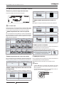
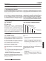
7.1 SETTING THE FILTER INDICATION INTERVAL
The FILTER interval indication on the remote control switch can be set a approximately 100, 1,200 or 2,500 hours (factory setting:
1,200 hours).
7.2 SETTING OF HIGH SPEED TAP
Ceiling height
Setting of remote control switch
1.0 to 2.5HP 3.0 to 6.0HP
Below 2.7m Below 3.2m Standard
2.7 to 3.0m 3.2 to 3.6m High Speed (1)
3.0 to 3.5m 3.6 to 4.2m High Speed (2)
The air ow volume can be changed according to the ceiling
height by setting the item code to “C5” form the remote control
switch (Refer to the Installation & Maintenance Manual of the
remote control switch for details).
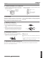
8 INSTALLATION OF OPTIONAL AIR PANEL: P-N23NA
8.1 FACTORY-SUPPLIED ACCESSORIES
! CAUTION
When the air panel is unpacked, place it on insulation material, etc. to
protect the sealing insulation from scratches
Check to ensure that the following accessories are packed with
the air panel.
If any of these accessories are not packed in the packing,
please contact your contractor.
Accessory Quantity Purpose
Long screw (M6×50) 4 For xing panel
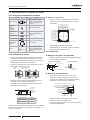
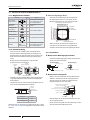
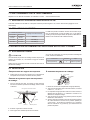
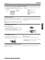
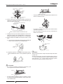
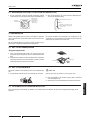
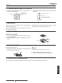
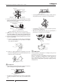
8.2 INSTALLATION
Location of suspension brackets
1 Check to ensure that the suspension brackets of the indoor
unit are located approximately 102mm higher the false
ceiling.
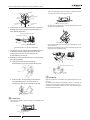
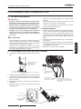
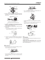
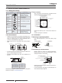
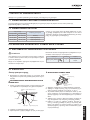
Removing air intake grille from air panel.
1 Open the air intake grille to an angle of approximately 45º
from the surface of the air panel as shown below.
Take up the grille keeping it inclined
Ceiling
45º
Air panel
Air lter
Air intake grille
Wrong
Correct
2 Lift the grille keeping it inclined
3 Draw the grille towards the open space after lifting.
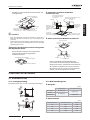
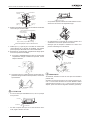
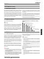
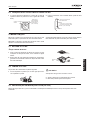
Installing air panel
b
a
c
d
Fixing nail
Fixing nail
L-Type hook
Fixing nail
1 Remove the cover of the corner pocket (4 portions).
2 Pull the xing nail towards the arrow mark according to the
order ”a”, ”b” and ”c”.
3 The corner pocket can be lifted. After lifting, move it in ”d”
direction, disconnect the L type hook and dismantle the
corner pocket.
4 Pull down theU-shaped hook (at 2 positions) located at the
indoor unit side.
REMOTE CONTROLLER OPERATION
PMML0253A rev.5 - 08/2016
9

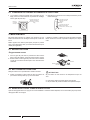
5 Set the corner fo the refrigerant connection portion of the
indoor unit to the position indicated as ”Ref. Piping”, and
hook the C-shapped hinge (2 positions) onto the U-shapped
hooks (2 positions) so that temporary positioning is available.
Electrical
control box
Indoor unit
Hook
Fixing plate
Air panel
Long screw
(Q’ty 4)
U-shaped hook
(Q’ty 2)
Stamp
“Ref Pipe”
6 Mount the air panel onto the air panel xing position by using
the factory-supplied xing screws (M6 cross screws).
Indoor unit undersurface
Fixing plate (indoor unit side)
Sealing gasket
Long screw
Fixing plate (Air panel side)
Panel
False ceiling
*
:Fix screw until this end touches it.
7 Check to ensure that there is no gap around the conctacting
surface between the indoor unit and the air panel. Any gap
may cause air leakage or dewing.
8 Attach the corner pocket covers after mounting air panel:
a. Hook the band at the rear side of the cover for the corner
pockets onto the pin of the panel as shown below.
Pin
Band
b. Hook the L-shapped nail located at the rear side of the
cover for the corner pockets onto the square hole of the
air panel.
L-shaped Nail
Fixing Nail (3 Portions)
! CAUTION
• If tighten long screws insufcient, may cause something wrong as
below.
Air Leakage
Smudge
Dewing
• If any gap has even though tighten long screws sufcient, readjust the
height of indoor unit.
No gap shall exist
• It’s able to adjust the indoor unit height by using wrench from the
corner pocket.
Wrench
• Too considerable adjustment of height cause dewing from drain-pain.
• Do not turn the air louver by hand. If moved, the louver mechanism
would be damaged.
Louver
Coin or slotted
screwdriver
Corner position
dent part
? NOTE
When the corner cover is to be removed after installing the air panel:
Insert a coin or a at-tipped screwdriver into the groove -1- and turn it
gently downwards. Perform the same operation in grooves -2- and -3-.
Lift the corner cover and, once the securing tabs (3 positions) have been
removed, remove it.
INSTALLATION OF OPTIONAL AIR PANEL: P-N23NA
PMML0253A rev.5 - 08/2016
10

ENGLISH
8.3 WIRING CONNECTION FOR AIR PANEL
1 The following connector is used with the air panel (view from
lower surface of air panel without air intake grille)
Electrical control
box
Connector for auto
swing motor (Low
voltage, 7Pin, red)
2 Connect the connectors as shown below (view of the
electrical box)
Electrical control box for
indoor unit
PCB
CN17
Connector for auto swing motor
(Low voltage, 7Pin, red)
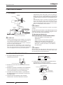
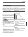
9 MAINTENANCE
Do not operate the system without the air lter to protect the
indoor unit heat exchanger against being clogged.
Turn OFF the main power switch before taking out the lter. (The
previous operation mode may appear.)
The indication, “FILTER” is shown on the display of the remote
control switch. Take out the air lter according to the indicated
steps for each unit.
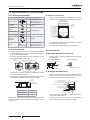
9.1 TAKE OUT THE FILTER
4-Way Cassette Type
1 Open the air inlet grille after pushing the two knobs toward
the arrow mark as shown in the gure below.
2 Take out the air lter from the air inlet grille by supporting the
air grille and lifting the air lter after detaching the lter from
two hinges
Knob
Air inlet grille
Hinges
Chain
Air lter
Air inlet grille
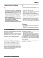
9.2 CLEAN THE FILTER
Clean the air lter according to the following steps:
1 Use a vacuum cleaner or let water ow onto the air lter for
removing the dirt from the air lter.
! CAUTION
Do not use hot water higher than approximately 40ºC.
2 Dry the air lter in the shade after shaking off moisture.
3 Do not use cleaner or other chemicals.
9.3 RESET OF FILTER INDICATION
After cleaning the air lter, press the “RESET” button. The FILTER indication will disappear and the next lter cleaning time is set.
MAINTENANCE
PMML0253A rev.5 - 08/2016
11


1 INFORMACIÓN GENERAL
1.1 NOTAS GENERALES
Ningún fragmento de esta publicación puede ser reproducida, co-
piada, archivada o transmitida en ninguna forma o medio sin per-
miso de Johnson Controls-Hitachi Air Conditioning Spain, S.A.U.
En una política de mejora continua de la calidad de sus produc-
tos, Johnson Controls-Hitachi Air Conditioning Spain, S.A.U. se
reserva el derecho de realizar cambios en cualquier momento,
sin comunicación previa y sin incurrir en la obligación de introdu-
cirlas en los productos vendidos con anterioridad. Por lo tanto,
este documento puede haber estado sometido a modicaciones
durante la vida del producto.
HITACHI realiza todos los esfuerzos posibles para ofrecer do-
cumentación actualizada y correcta. Pese a ello, los errores de
impresión están fuera del control de HITACHI, que no se hace
responsable de ellos.
En consecuencia, algunas de las imágenes o algunos de los da-
tos empleados para ilustrar este documento pueden no corres-
ponder a modelos concretos. No se admitirán reclamaciones ba-
sadas en los datos, ilustraciones y descripciones de este manual.
No debe efectuarse ningún tipo de modicación en el equipo sin
la autorización previa, y por escrito, del fabricante.
1.2 GUÍA DE PRODUCTOS
1.2.1 Comprobación previa
? NOTA
Comprobar, de acuerdo con el nombre del modelo, el tipo de sistema
de aire acondicionado del que dispone, su abreviatura y su referencia
en el presente manual de instrucciones. Este manual de instalación y
funcionamiento hace referencia únicamente a las unidades RCI-(1.0-6.0)
FSN3Ei.
Comprobar, de acuerdo con los Manuales de Instalación y Fun-
cionamiento incluidos en las unidades exteriores e interiores, que
se incluye toda la información necesaria para la correcta instala-
ción del sistema. Si no fuera el caso, póngase en contacto con
su distribuidor.
1.2.2 Nomenclatura de modelos de unidades
interiores
Tipo de unidad (unidad interior): RCI
Guión separador de posición (jo)
Capacidad (CV): (1,0-6,0)
FS : SYSTEM FREE
N: refrigerante R410A
3 : Serie
E: Made in Europe
i = Versión mejorada
XXX – XX FS N 3 E i
1.3 SEGURIDAD
1.3.1 Simbología aplicada
Durante los trabajos habituales de diseño de sistemas de clima-
tización o de instalación de equipos, es necesario prestar mayor
atención en algunas situaciones que requieren conducirse de
manera especialmente cuidadosa, para evitar daños en perso-
nas, el equipo, en la instalación o en el edicio o inmueble.
Aquellas situaciones que puedan comprometer la integridad de
las personas o pongan en peligro el equipo se señalarán de for-
ma clara en este manual.
Para ello se emplearán una serie de símbolos especiales que
identicarán claramente estas situaciones.
Preste mucha atención a estos símbolos y a los mensajes que
les siguen, pues de ello depende su propia seguridad y la de los
demás.
! PELIGRO
• Los textos precedidos de este símbolo contienen informaciones
e indicaciones relacionadas directamente con su seguridad e
integridad física.
• Si no se tienen en cuenta dichas indicaciones puede resultar
herido grave, muy grave o incluso mortalmente, tanto usted
como otras personas que se encuentren cerca del equipo.
En los textos precedidos del símbolo de peligro, también puede
encontrar información sobre formas seguras de proceder durante
la instalación del equipo.
! PRECAUCIÓN
• Los textos precedidos de este símbolo contienen informaciones e
indicaciones relacionadas directamente con su seguridad e integri-
dad física.
• Si no se tienen en cuenta dichas indicaciones puede sufrir lesiones
leves, tanto usted como otras personas que se encuentren cerca del
equipo.
• No tener en cuenta estas indicaciones puede provocar daños en el
equipo.
En los textos precedidos del símbolo de precaución, también
puede encontrar información sobre formas seguras de proceder
durante la instalación del equipo.
? NOTA
• Los textos precedidos de este símbolo contienen informaciones o
indicaciones que pueden resultar útiles, o que merecen una expli-
cación más extensa.
• También puede incluir indicaciones acerca de comprobaciones que
deben efectuarse sobre elementos o sistemas del equipo.
INFORMACIÓN GENERAL
PMML0253A rev.5 - 08/2016
13
ESPAÑOL

1.3.2 Información adicional relativa a la seguridad
! PELIGRO
• HITACHI no puede prever todas las circunstancias que pudieran
conllevar un peligro potencial.
• No vierta agua en la unidad interior ni en la exterior. Estos pro-
ductos están equipados con piezas eléctricas. Si el agua entra
en contacto con los componentes eléctricos se producirá una
descarga eléctrica grave.
• No manipule ni realice ajustes en los dispositivos de seguridad
dentro de las unidades interior y exterior. Si estos dispositivos
son manipulados o ajustados puede provocar un accidente
grave.
• No abra la tapa de servicio ni el panel de acceso de las unidades
interior y exterior sin desconectar la alimentación principal.
• En caso de incendio, desconecte el interruptor principal, extinga
el fuego de inmediato y póngase en contacto con su proveedor
de servicios.
• Compruebe que el cable de tierra está rmemente conectado.
• Conecte la unidad a un disyuntor y/o a un interruptor automático
de la capacidad especicada.
! PRECAUCIÓN
• Las fugas de refrigerante pueden dicultar la respiración, ya que de-
splazan el aire de la estancia.
• Instale la unidad interior, la unidad exterior, el mando remoto y el
cable a una distancia mínima aproximada de 3 metros de fuentes de
fuertes radiaciones de ondas electromagnéticas, como, por ejemplo,
equipos médicos.
• No emplee ningún tipo de aerosoles, como insecticidas, barnices o
lacas, ni ningún otro gas inamable a menos de aproximadamente
un metro del sistema.
• Si el disyuntor, interruptor automático o el fusible de alimentación de
la unidad se activa con frecuencia, detenga el sistema y póngase en
contacto con el proveedor de servicios.
• No realice ninguna tarea de mantenimiento o inspección por su cuen-
ta. Éstas tareas deben ser realizadas por personal de servicio cuali-
cado y con las herramientas y medios adecuados para ello.
• No coloque ningún material extraño (ramas, palos, etc.) en la entrada
ni en la salida de aire de la unidad. Estas unidades disponen de ven-
tiladores con alta velocidad de rotación y el contacto de éstos con
cualquier objeto es peligroso.
• Este dispositivo debe ser utilizado únicamente por un adulto o por
una persona responsable que haya recibido formación o instruc-
ciones técnicas de cómo manipularlo de forma adecuada y segura.
• Es preciso vigilar a los niños para que no jueguen con el dispositivo.
? NOTA
• Es recomendable renovar el aire de la estancia y ventilar cada 3 o
4 horas.
• El instalador y el especialista en sistemas proporcionarán seguridad
antifugas de acuerdo con la normativa local.
1.4 AVISO IMPORTANTE
Este sistema de aire acondicionado se ha diseñado para sumi-
nistrar aire acondicionado a las personas. Para otros usos pón-
gase en contacto con su proveedor o distribuidor de HITACHI.
La instalación del sistema de aire acondicionado sólo debe ser
realizada por personas cualicadas, que disponen de los medios,
herramientas y equipos necesarios para ello y que, además, co-
nocen todos los procedimientos de seguridad necesarios para
llevarla a cabo con garantías.
En el CD-ROM que se incluye con la unidad exterior encontrará
información adicional acerca del producto adquirido. Si no tiene
el CD-ROM o si es ilegible contacte con su proveedor o distribui-
dor HITACHI.
LEA ATENTAMENTE EL MANUAL Y EL CONTENIDO DEL CD-
ROM ANTES DE INICIAR LAS TAREAS DE INSTALACIÓN
DEL SISTEMA DE AIRE ACONDICIONADO. El incumplimiento
de las instrucciones de instalación, uso y funcionamiento descri-
tas en este documento puede provocar fallos de funcionamiento
potencialmente graves, o incluso la destrucción del sistema.
Compruebe, en los manuales de las unidades interior y exterior,
que dispone de toda la información necesaria para la correcta
instalación del sistema. Si no es así, póngase en contacto con
su distribuidor.
Se presupone que este sistema de aire acondicionado se insta-
lará y se mantendrá por personal responsable capacitado para
ello. En caso contrario, el cliente debe incorporar todas las se-
ñales de seguridad, precaución y funcionamiento en el idioma
nativo del personal responsable.
No instalar la unidad en los siguientes lugares; puede provocar
un incendio, deformaciones, corrosión o fallos:
• Lugares con presencia de aceite (incluyendo aceite para
máquinas).
• Lugares en los que hay una alta concentración de gas
sulfuroso, tales como balnearios.
• Lugares donde pueden generarse o uir gases inamables.
• En entornos salinos, ácidos o alcalinos.
No instale la unidad en lugares con presencia de gas de silicio. Si
el gas de silicio se deposita sobre la supercie del intercambiador
de calor, éste repele el agua. Como resultado, el agua conden-
sada salpica fuera de la bandeja de recogida y llega hasta el
interior de la caja eléctrica. Finalmente, pueden producirse fugas
de agua o fallos eléctricos.
No instale la unidad en un emplazamiento donde la corriente de
aire expelida afecte directamente a animales o plantas; puede
afectarles de forma adversa.
INFORMACIÓN GENERAL
PMML0253A rev.5 - 08/2016
14
A página está carregando...
A página está carregando...
A página está carregando...
A página está carregando...
A página está carregando...
A página está carregando...
A página está carregando...
A página está carregando...
A página está carregando...
A página está carregando...
A página está carregando...
A página está carregando...
A página está carregando...
A página está carregando...
A página está carregando...
A página está carregando...
A página está carregando...
A página está carregando...
A página está carregando...
A página está carregando...
A página está carregando...
A página está carregando...
A página está carregando...
A página está carregando...
A página está carregando...
A página está carregando...
A página está carregando...
A página está carregando...
A página está carregando...
A página está carregando...
A página está carregando...
A página está carregando...
A página está carregando...
A página está carregando...
A página está carregando...
A página está carregando...
A página está carregando...
A página está carregando...
A página está carregando...
A página está carregando...
A página está carregando...
A página está carregando...
A página está carregando...
A página está carregando...
A página está carregando...
A página está carregando...
A página está carregando...
A página está carregando...
A página está carregando...
A página está carregando...
A página está carregando...
A página está carregando...
A página está carregando...
A página está carregando...
A página está carregando...
A página está carregando...
A página está carregando...
A página está carregando...
A página está carregando...
A página está carregando...
A página está carregando...
A página está carregando...
A página está carregando...
A página está carregando...
A página está carregando...
A página está carregando...
A página está carregando...
A página está carregando...
A página está carregando...
A página está carregando...
A página está carregando...
A página está carregando...
A página está carregando...
A página está carregando...
A página está carregando...
A página está carregando...
A página está carregando...
A página está carregando...
A página está carregando...
A página está carregando...
A página está carregando...
A página está carregando...
A página está carregando...
A página está carregando...
A página está carregando...
A página está carregando...
A página está carregando...
A página está carregando...
A página está carregando...
A página está carregando...
A página está carregando...
A página está carregando...
A página está carregando...
A página está carregando...
A página está carregando...
A página está carregando...
A página está carregando...
A página está carregando...
A página está carregando...
A página está carregando...
A página está carregando...
A página está carregando...
A página está carregando...
A página está carregando...
A página está carregando...
A página está carregando...
A página está carregando...
A página está carregando...
-
 1
1
-
 2
2
-
 3
3
-
 4
4
-
 5
5
-
 6
6
-
 7
7
-
 8
8
-
 9
9
-
 10
10
-
 11
11
-
 12
12
-
 13
13
-
 14
14
-
 15
15
-
 16
16
-
 17
17
-
 18
18
-
 19
19
-
 20
20
-
 21
21
-
 22
22
-
 23
23
-
 24
24
-
 25
25
-
 26
26
-
 27
27
-
 28
28
-
 29
29
-
 30
30
-
 31
31
-
 32
32
-
 33
33
-
 34
34
-
 35
35
-
 36
36
-
 37
37
-
 38
38
-
 39
39
-
 40
40
-
 41
41
-
 42
42
-
 43
43
-
 44
44
-
 45
45
-
 46
46
-
 47
47
-
 48
48
-
 49
49
-
 50
50
-
 51
51
-
 52
52
-
 53
53
-
 54
54
-
 55
55
-
 56
56
-
 57
57
-
 58
58
-
 59
59
-
 60
60
-
 61
61
-
 62
62
-
 63
63
-
 64
64
-
 65
65
-
 66
66
-
 67
67
-
 68
68
-
 69
69
-
 70
70
-
 71
71
-
 72
72
-
 73
73
-
 74
74
-
 75
75
-
 76
76
-
 77
77
-
 78
78
-
 79
79
-
 80
80
-
 81
81
-
 82
82
-
 83
83
-
 84
84
-
 85
85
-
 86
86
-
 87
87
-
 88
88
-
 89
89
-
 90
90
-
 91
91
-
 92
92
-
 93
93
-
 94
94
-
 95
95
-
 96
96
-
 97
97
-
 98
98
-
 99
99
-
 100
100
-
 101
101
-
 102
102
-
 103
103
-
 104
104
-
 105
105
-
 106
106
-
 107
107
-
 108
108
-
 109
109
-
 110
110
-
 111
111
-
 112
112
-
 113
113
-
 114
114
-
 115
115
-
 116
116
-
 117
117
-
 118
118
-
 119
119
-
 120
120
-
 121
121
-
 122
122
-
 123
123
-
 124
124
-
 125
125
-
 126
126
-
 127
127
-
 128
128


em outras línguas
- español: Hitachi P-N23NA Instrucciones de operación
- français: Hitachi P-N23NA Mode d'emploi
- italiano: Hitachi P-N23NA Istruzioni per l'uso
- English: Hitachi P-N23NA Operating instructions
- Nederlands: Hitachi P-N23NA Handleiding
- Deutsch: Hitachi P-N23NA Bedienungsanleitung
- dansk: Hitachi P-N23NA Betjeningsvejledning
- svenska: Hitachi P-N23NA Bruksanvisningar
Artigos relacionados
-
Hitachi P-G23WA2 Guia de instalação
-
-
-
Hitachi RAS-8HNPE Instruções de operação
-
-
-
-
-
Hitachi RPIL-(0.4-1.5)FSRE Ducted Indoor Units Manual do usuário
-
Outros documentos
-
Sanyo SPW-XR254EH56 Manual do usuário
-
LG ARNU48GV2A4 Guia de instalação
-
Mitsubishi Electric PLFY-P-VAM-E Guia de instalação
-
LG AVNW36GM1P0 Guia de instalação
-
 ESS BD-80-Z Guia de instalação
-
Sony SA-VE100 Manual do proprietário
-
 ESS SBAquaB Guia de instalação
-
KEF Ci50R-WH Manual do proprietário
-
KEF CI50 Guia de instalação
-
WEG CFW11 Manual do usuário

