
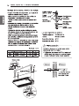
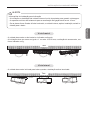
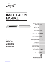
Ceiling Suspended Air Conditioner
Original instruction
P/NO : MFL67107614
REV.01_021517
INSTALLATION MANUAL
AIR
CONDITIONER
www.lg.com
Please read this installation manual completely before install-
ing the product.
Installation work must be performed in accordance with the
national wiring standards by authorized personnel only.
please retain this installation manual for future reference after
reading it thoroughly
ENGLISH
ESPAÑOL
PORTUGUÊS
Models:
ARNU18GV1A4 ARNU24GV1A4 ARNU36GV2A4 ARNU48GV2A4

2
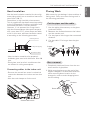
TIPS FOR SAVING ENERGY
ENGLISH
• Do not cool excessively indoors. This may be harmful for your health and may consume more
electricity.
• Block sunlight with blinds or curtains while you are operating the air conditioner.
• Keep doors or windows closed tightly while you are operating the air conditioner.
• Adjust the direction of the air flow vertically or horizontally to circulate indoor air.
• Speed up the fan to cool or warm indoor air quickly, in a short period of time.
• Open windows regularly for ventilation as the indoor air quality may deteriorate if the air condi-
tioner is used for many hours.
• Clean the air filter once every 2 weeks. Dust and impurities collected in the air filter may block the
air flow or weaken the cooling / dehumidifying functions.
For your records
Staple your receipt to this page in case you need it to prove the date of purchase or for warranty
purposes. Write the model number and the serial number here:
Model number :
Serial number :
You can find them on a label on the side of each unit.
Dealer’s name :
Date of purchase :
Here are some tips that will help you minimize the power consumption when you use the air
conditioner. You can use your air conditioner more efficiently by referring to the instructions
below:
TIPS FOR SAVING ENERGY

IMPORTANT SAFETY INSTRUCTIONS
3
ENGLISH
IMPORTANT SAFETY INSTRUCTIONS
READ ALL INSTRUCTIONS BEFORE USING THE APPLIANCE.
Always comply with the following precautions to avoid dangerous situations and ensure peak
performance of your product
WARNING
It can result in serious injury or death when the directions are ignored
CAUTION
It can result in minor injury or product damage when the directions are ignored
WARNING
• Installation or repairs made by unqualified persons can result in hazards to you and others.
• Installation MUST conform with local building codes.
• The information contained in the manual is intended for use by a qualified service technician
familiar with safety procedures and equipped with the proper tools and test instruments.
• Failure to carefully read and follow all instructions in this manual can result in equipment mal-
function, property damage, personal injury and/or death.
Installation
• Don’t use a power cord, a plug or a loose socket which is damaged.
- Otherwise, it may cause a fire or electrical shock.
• For electrical work, contact the dealer, seller, a qualified electrician, or an Authorized Service Center.
- Do not disassemble or repair the product. There is risk of fire or electric shock.
• Always ground the product.
- There is risk of fire or electric shock.
• Install the panel and the cover of control box securely.
- There is risk of fire or electric shock.
• Always install a dedicated circuit and breaker.
- Improper wiring or installation may cause fire or electric shock.
• Use the correctly rated breaker or fuse.
- There is risk of fire or electric shock.
• Do not modify or extend the power cable.
- There is risk of fire or electric shock.
• Do not let the air conditioner run for a long time when the humidity is very high and a door or a win-
dow is left open.
- Moisture may condense and wet or damage furniture.
• Be cautious when unpacking and installing the product.
- Sharp edges could cause injury. Be especially careful of the case edges and the fins on the con-
denser and evaporator.
• For installation, always contact the dealer or an Authorized Service Center.
- There is risk of fire, electric shock, explosion, or injury.
!
!
!

4
IMPORTANT SAFETY INSTRUCTIONS
ENGLISH
• Do not install the product on a defective installation stand.
- It may cause injury, accident, or damage to the product.
• Be sure the installation area does not deteriorate with age.
- If the base collapses, the air conditioner could fall with it, causing property damage, product failure,
and personal injury.
• There is a risk of fire and explosion.
- Inert gas (nitrogen) should be used when you check plumbing leaks, cleaning or repairs of pipes
etc.
If you are using combustible gases including oxygen, product may have the risk of fires and explo-
sions.
• Use a vacuum pump or Inert (nitrogen) gas when doing leakage test or air purge. Do not compress
air or Oxygen and do not use Flammable gases. Otherwise, it may cause fire or explosion.
- There is the risk of death, injury, fire or explosion.
Operation
• Do not store or use flammable gas or combustibles near the product.
- There is risk of fire or failure of product.
CAUTION
Installation
• Always check for gas (refrigerant) leakage after installation or repair of product.
- Low refrigerant levels may cause failure of product.
• Install the drain hose to ensure that water is drained away properly.
- A bad connection may cause water leakage.
• Keep level even when installing the product.
- To avoid vibration or water leakage.
• Use two or more people to lift and transport the product.
- Avoid personal injury.
!

TABLE OF CONTENTS
5
ENGLISH
2 TIPS FOR SAVING EN-
ERGY
3 IMPORTANT SAFETY IN-
STRUCTIONS
6 PRODUCT PARTS
6 INSTALLATION TOOLS
7 INSTALLATION
7 Select the best Location
8 THE INDOOR UNIT IN-
STALLATION
9 Open side-cover
10 Mounting the anchor nut and bolt
12 Indoor unit drain piping
12 Drain piping
12 Drain test
13 Heat insulation
13 Flaring Work
16 Wiring Connection
17 DIP Switch Setting
18 Group Control Setting
23 Model Designation
23 Airborne Noise Emission
23 Limiting concentration
TABLE OF CONTENTS

6
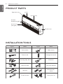
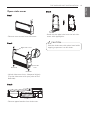
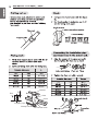
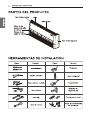
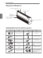
PRODUCT PARTS
ENGLISH
PRODUCT PARTS
INSTALLATION TOOLS
Air outlet vent
Air inlet vent
(inlet grille)
Air filters
(behind inlet grille)
Louver
Right side cover
Left side cover
Figure FigureName
Screw driver
Electric drill
Measuring tape, Knife
Hole core drill
Spanner
Torque wrench
Multi-meter
Hexagonal wrench
Ammeter
Gas-leak detector
Thermometer,
Level
Flaring tool set
Name

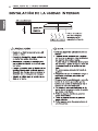
INSTALLATION MAP
7
ENGLISH
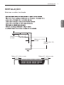
INSTALLATION
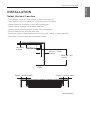
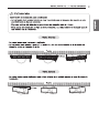
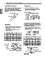
Select the best Location
- There should not be any heat source or steam near the unit.
- There should not be any obstacles to prevent the air circulation.
- A place where air circulation in the room will be good.
- A place where drainage can be easily obtained.
- A place where noise prevention is taken into consideration.
- Do not install the unit near the door way.
- Ensure the spaces indicated by arrows from the wall, ceiling, or other obstacles.
- The indoor unit must keep the maintenance space.
700(27 – 9/16) or more
unit:mm(inch)
700(27 – 9/16) or more
2500 (98 – 3/7)
or more
Floor
10 (13/32)
or more
300 (11 – 13/16)
or more

8
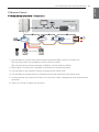
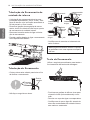
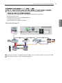
THE INDOOR UNIT INSTALLATION
ENGLISH
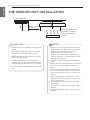
THE INDOOR UNIT INSTALLATION
Use the ventilation fan
for smoke-collecting
hood with sufficient
capacity.
Cooking table
Air conditioner
Take enough
distance
• Install the unit horizontally using a level
gauge.
• During the installation, care should be
taken not to damage electric wires.
• Select and mark the position for fixing
bolts and piping hole.
• Decide the position for fixing bolts
slightly tilted to the drain direction after
considering the direction of drain hose.
• Drill the hole for anchor bolt on the ceil-
ing.
CAUTION
!
NOTE
!
• Avoid the following installation location.
1. Such places as restaurants and kitchen
where considerable amount of oil
steam and flour is generated.
These may cause heat exchange effi-
ciency reduction, or water drops, drain
pump mal-function.
In these cases, take the following ac-
tions;
• Make sure that ventilation fan is enough
to cover all noxious gases from this
place.
• Ensure enough distance from the cook-
ing room to install the air conditioner in
such a place where it may not suck oily
steam.
2. Avoid installng air conditioner in such
places where cooking oil or iron pow-
der is generated.
3. Avoid places where inflammable gas is
generated.
4. Avoid place where noxious gas is gen-
erated.
5. Avoid places near high frequency gen-
erators.

THE INDOOR UNIT INSTALLATION
9
ENGLISH
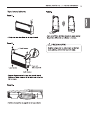
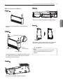
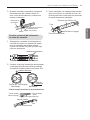
Open side-cover
Step 1
Backside
Right side cover
Backside
Left side
cover
Step 2
- Remove two screws from side-cover.
Step 3
Step 4
- Remove paper bracket from side-cover.
- Unlock side-cover from side-panel slightly
(Tap the side-cover with your palm on the
backside)
- Knock out the pipe hole from the left side-
cover with nipper/plier.
Hold the side-cover with other hand while
tapping to prevent it to fall down.
CAUTION
!

10
THE INDOOR UNIT INSTALLATION
ENGLISH
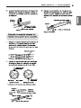
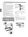
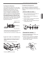
Mounting the anchor nut and
bolt
- Prepare 4 suspension bolts. (Each bolts
length should be same.)
- Measure and mark the position for the
Suspension bolts and the piping hole.
- Drill the hole for anchor nut on the ceiling.
- Insert the nuts and washer onto the suspen-
sion bolts for locking the suspension bolts on
the ceiling.
- Mount the suspension bolts to the anchor-
nuts firmly.
- Secure the hangers onto the Suspension
bolts (adjust level roughly.) using nuts, wash-
ers and spring washers.
- Adjust a level with a level gauge on the
direction of left-right, back-forth by adjusting
suspension bolts.
- Adjust a level on the direction of top-bottom
by adjusting supension bolts. Then the unit
will be declined to the bottomside so as to
drain well.
- The following parts is option.
Hanging Bolt - W 3/8 or M10
Nut - W 3/8 or M10
Spring Washer - M10
Plate Washer - M10
(Unit : mm)
Suspension bolt
B
A
Nut
Ceiling
Anchor nut
Washer
Washer
Washer
Suspension
Suspension
bolts
bolts
Suspension
bolts
Spring
washer
Max.
12mm
Nut
Suspension
bolts
Hangen
Washer
Hanging bolt
(W3/8 or M10)
Nut
(W3/8 or M10)
Spring washer
(M10)
Flat washer
for M10
(accessory)
Flat washer
for M10
(accessory)
Nut
(W3/8 or M10)
Wall
Indoor
Outdoor
Slope gradient for
drain Should be
1/50 ~ 1/100
Chassis Code A B
VM1 ARNU**GV1A4 1018 355
VM2 ARNU**GV2A4 1418 355
Tighten the nut and bolt to prevent unit
from falling
• Drill the piping hole on the wall slightly
tilted to the outdoor side by using a
Ø 70 hole-core drill.
CAUTION
!

THE INDOOR UNIT INSTALLATION
11
ENGLISH
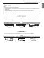
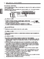
Installation information for declination
- Install declination of the indoor unit is very important for the drain of the convertible type air
conditioner.
- Minimum thickness of the insulation for the connecting pipe shall be 10 mm.
- If the Installation Plates are fixed to horizontal line, the indoor unit after installing will be de-
clined to the bottomside.
CAUTION
!
Front of view
- The unit must be horizontal or inclined at angle.
- The inclination should be less than or equal to 1° or in between 10 to 20 mm inclined in drain
direction as shown in fig.
Ceiling
10~20 mm
Side of view
- The unit must be inclined to the bottomside of the unit when finished installation.
Ceiling
5~10 mm

12
THE INDOOR UNIT INSTALLATION
ENGLISH
Indoor unit drain piping
- Drain piping must have down-slope (1/50 to
1/100): be sure not to provide up-and-down
slope to prevent reversal flow.
- During drain piping connection, be careful
not to exert extra force on the drain port on
the indoor unit.
- Remove the rubber stopple before connect-
ing drain hose.
- Hook on the bracket after connecting the
drain hose as below.
Drain piping
- The drain hose should point downward for
easy drain flow.
- Do not make drain piping like the following.
- Be sure to execute heat insulation on the
drain piping.
Drain test
Use the following procedure to test the drain
pump operation:
- Set the air direction louvers up-and-down to
the position(horizontally) by hand.
- Pour a glass of water on the evaporator
using a kettle.
- Ensure the water flows through the drain
hose of the indoor unit without any leakage
and goes out the drain exit.
Drain hose
Bracket
Downward
slope
Do not raise
Accumulated
drain water
Air
Waving
Water
leakage
Water
leakage
Ditch
Less than
50 mm gap
Water
leakage
Tip of drain
hose dipped
in water
Heat insulation material: Polyethylene foam
with thickness more than 8 mm.

THE INDOOR UNIT INSTALLATION
13
ENGLISH
Heat insulation
Use the heat insulation material for the refrig-
erant piping which has an excellent heat-resis-
tance (over 120 °C).
Precautions in high humidity circumstance:
This air conditioner has been tested according
to the "KS Standard Conditions with Mist" and
confirmed that there is not any default.
However, if it is operated for a long time in
high humid atmosphere (dew point tempera-
ture: more than 23 °C), water drops are liable
to fall. In this case, add heat insulation materi-
al according to the following procedure:
- Heat insulation material to be prepared...
Adiabatic glass wool with thickness 10 to 20
mm.
- Stick glass wool on all air conditioners that
are located in ceiling atmosphere.
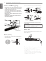
Connecting cables to the indoor unit
- Remove the control box cover for electrical
connection between the indoor and out door
unit
- Use the cord clamper to fix the cord.
Flaring Work
Main cause for gas leakage is due to defect of
flaring work. Carry out correct flaring work in
the following procedure.
1 Use the piping kit accessory or the pipes
purchased locally.
2 Measure the distance between the indoor
and the outdoor unit.
3 Cut the pipes a little longer than measured
distance.
4 Cut the cable 1.5m longer than the pipe
length.
1. Completely remove all burrs from the cut
cross section of pipe/tube.
2. While removing burrs put the end of the
copper tube/pipe in a downward direction
while removing burrs location is also
changed in order to avoid dropping burrs
into the tubing.
Indoor unit
Thermal insulator
Fastening band
Refrigerant piping
Control box cover
Cut the pipes and the cable
Burrs removal
Copper
pipe
90°
Slanted Uneven Rough
Pipe
Reamer
Point down

Bar
Copper pipe
Clamp handle
Red arrow mark
Cone
Yoke
Handle
Bar
"A"

THE INDOOR UNIT INSTALLATION
15
ENGLISH
3 When needed to extend the drain hose of
indoor unit, assembly the drain pipe as
shown on the drawing
1 Overlap the connection pipe insulation ma-
terial and the indoor unit pipe insulation
material. Bind them together with vinyl
tape so that there may be no gap.
2 Set the tubing cutting line upward.
Wrap the area which accommodates the
rear piping housing section with vinyl tape.
3 Bundle the piping and drain hose together
by wrapping them with vinyl tape sufficient
enough to cover where they fit into the
rear piping housing section.
Vinyl tape(narrow)
Adhesive
Drain pipe
Indoor unit drain hose
Wrap the insulation material
around the connecting portion.
Insulation material
Gas Pipe
Liquid Pipe
Cutting Line
Cutting Line
Good Case Bad Case
* Tubing cutting line have to be upward.
Vinyl tape(narrow)
Connection pipe
Connecting cable
Vinyl tape (wide)
Wrap with vinyl tape
Indoor unit pipe
Pipe
Wrap with vinyl tape
Drain hose
Pipe
Vinyl tape(wide)

-B -A

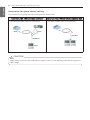
17
ENGLISH
THE INDOOR UNIT INSTALLATION
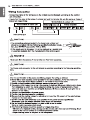
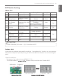
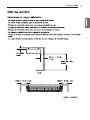
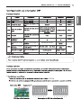
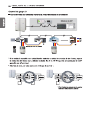
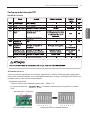
DIP Switch Setting
Indoor Unit
Outdoor Unit
In case that the products meet specific conditions, “Auto addressing” function can start automat-
ically with the improved speed by turning the DIP switch #3 of the outdoor unit and resetting the
power.
* Specific conditions:
- All names of the indoor units are ARNU******4
- The serial number of (outdoor units) should be after October 2013.
CAUTION
For Multi V Models, DIP switch 1, 2, 6, 8 must be set OFF.
!
Function Description Setting Off Setting On Default
SW1 Communication N/A (Default) - - Off
SW2 Cycle N/A (Default) - - Off
SW3 Group Control
Selection of Master
or Slave
Master Slave Off
SW4
Dry Contact
Mode
Selection of Dry Con-
tact Mode
Wired/Wireless remote
controller
Selection of Manual or
Auto operation Mode
Auto
Off
SW5 Position
Selection of installa-
tion position
Ceiling Bottom Off
SW6 Heater linkage N/A - - Off
SW7
Ventilator link-
age
Selection of Ventila-
tor linkage
Linkage Removal
Working
Off
Vane selection
(Console)
Selection of up/down
side Vane
Up side + Down side
Vane
Up side Vane
Only
Region selection
Selection tropical re-
gion
General model Tropical model
SW8 Etc. Spare - - Off
DIP switch 7 segment
Outdoor Unit PCB Outdoor Unit DIP Switch


19
ENGLISH
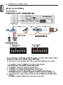
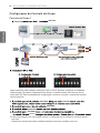
THE INDOOR UNIT INSTALLATION
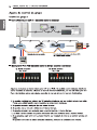
GND
Signal
12 V
Slave
Slave
Master
or
Donʼt connect serial 12V line
LGAP Network System
Master
SlaveMaster
Display Error Message
Group Control 2
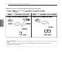
■ Wired remote controllers + Standard Indoor Units
* It is possible to connect indoor units since Feb. 2009.
* It can be the cause of malfuctions when there is no setting of master and slave.
* In case of Group Control, it is possible to use following functions.
- Selection of operation, stop or mode
- Temperature setting and room temperature check
- Current time change
- Control of flow rate (High/Middle/Low)
- Reservation settings
- It is not possible at some functions.
* It is possible to control 16 indoor units(Max.) with the master wired remote control.
* Other than those, it is same with the Group Control 1.

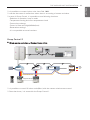
20
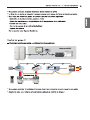
GND
Signal
12 V
LGAP Network System
FAU
Master
FAU
or
Slave
Master
Slave
Master
Master
Display Error Message
Display Error Message
N
M
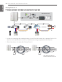
ENGLISH
THE INDOOR UNIT INSTALLATION
Group Control 3
■ Mixture connection with indoor units and Fresh Air Intake Unit
* In case of connecting with standard indoor unit and Fresh Air Intake Unit, separate Fresh Air In-
take Unit with standard units. (N, M ≤ 16) (Because setting temperature are different.)
* Other than those, it is same with Group Control 1.
FAU
Standard Standard
FAU FAU
Standard Standard
FAU
* FAU : Fresh Air Intake Unit
Standard: Standard Indoor Unit
A página está carregando...
A página está carregando...
A página está carregando...
A página está carregando...
A página está carregando...
A página está carregando...
A página está carregando...
A página está carregando...
A página está carregando...
A página está carregando...
A página está carregando...
A página está carregando...
A página está carregando...
A página está carregando...
A página está carregando...
A página está carregando...
A página está carregando...
A página está carregando...
A página está carregando...
A página está carregando...
A página está carregando...
A página está carregando...
A página está carregando...
A página está carregando...
A página está carregando...
A página está carregando...
A página está carregando...
A página está carregando...
A página está carregando...
A página está carregando...
A página está carregando...
A página está carregando...
A página está carregando...
A página está carregando...
A página está carregando...
A página está carregando...
A página está carregando...
A página está carregando...
A página está carregando...
A página está carregando...
A página está carregando...
A página está carregando...
A página está carregando...
A página está carregando...
A página está carregando...
A página está carregando...
A página está carregando...
A página está carregando...
A página está carregando...
A página está carregando...
A página está carregando...
A página está carregando...
-
 1
1
-
 2
2
-
 3
3
-
 4
4
-
 5
5
-
 6
6
-
 7
7
-
 8
8
-
 9
9
-
 10
10
-
 11
11
-
 12
12
-
 13
13
-
 14
14
-
 15
15
-
 16
16
-
 17
17
-
 18
18
-
 19
19
-
 20
20
-
 21
21
-
 22
22
-
 23
23
-
 24
24
-
 25
25
-
 26
26
-
 27
27
-
 28
28
-
 29
29
-
 30
30
-
 31
31
-
 32
32
-
 33
33
-
 34
34
-
 35
35
-
 36
36
-
 37
37
-
 38
38
-
 39
39
-
 40
40
-
 41
41
-
 42
42
-
 43
43
-
 44
44
-
 45
45
-
 46
46
-
 47
47
-
 48
48
-
 49
49
-
 50
50
-
 51
51
-
 52
52
-
 53
53
-
 54
54
-
 55
55
-
 56
56
-
 57
57
-
 58
58
-
 59
59
-
 60
60
-
 61
61
-
 62
62
-
 63
63
-
 64
64
-
 65
65
-
 66
66
-
 67
67
-
 68
68
-
 69
69
-
 70
70
-
 71
71
-
 72
72


LG ARNU48GV2A4 Guia de instalação
- Tipo
- Guia de instalação
- Este manual também é adequado para
em outras línguas
- English: LG ARNU48GV2A4 Installation guide
Artigos relacionados
-
LG PM07SP.NSJ Guia de instalação
-
LG URNU48GVLA2 Manual do usuário
-
LG AVNW36GM1P0 Guia de instalação
-
LG AVNQ36GM1A0 Guia de instalação
-
-
-
LG A3UW24GFAB.AWGTLAT Manual do proprietário
-
-
LG ARUN200BTE4.AWGBLAT Guia de instalação
-
Outros documentos
-
Carrier Split-type Room Air Conditioner Manual do proprietário
-
Mitsubishi PAC-AK52BC Guia de instalação
-
Mitsubishi Electric CITY MULTI PEFY-P-VMH-A-F Series Guia de instalação
-
Toshiba MMU-AP0071YH Manual do usuário
-
-
-
 Siesta AHQ100CV1 Guia de instalação
-
Sanyo SPW-XR254EH56 Manual do usuário
-
Toshiba MMD-AP0071SPH Manual do proprietário
-
