
Supporto a bandiera per paranco elettrico
ISTRUZIONI PER L’USO E ISTRUZIONI DI SICUREZZA
Istruzioni originali
Supportagtoelectrichoist
INSTRUCTION MANUAL AND SAFETY INSTRUCTIONS
Translation of the original instructions
M450554
02.02.2017
ATTENZIONE!Primadiusareilprodotto,leggeteattentamenteleistruzioniperl’uso
CAUTION!Beforestartingtheproduct,readtheoperatinginstructionscarefully
DICHIARAZIONE DI CONFORMITA’
La ditta indicata in etichetta dichiara sotto la
propria responsabilità che il prodotto ivi citato
è conforme ai requisiti essenziali di sicurezza e
salute contenuti nelle seguenti direttive europee:
2006/42/CE
DECLARATION OF CONFORMITY
The firm indicated on the label declares, under
its own responsibility, that the product cited
there complies with the essential health and
safety requirements contained in the following
European directives:
2006/42/EC
Persona autorizzata a costituire il fascicolo tec-
nico presso/ The person authorized to compile
the technical file is in
Valex SpA - Via Lago Maggiore 24
36015 Schio (VI) - Italy
Schio, 02.2017
Un procuratore - Attorney
SMIDERLE STEFANO

- 2 -
i
ATTENZIONE! Leggete ed applicate attenta-
mente le istruzioni di seguito riportate.
La mancata ottemperanza alle avvertenze e
alle istruzioni può dare luogo a incidenti e/o
lesioni serie.
La scrupolosa osservanza di queste avver-
tenze con l’utilizzo dei mezzi di protezione
individuale, minimizzano i rischi di incidente
ma non li eliminano completamente.
Utilizzate questo supporto solo nei modi de-
scritti in queste
istruzioni. Non utilizzatelo per scopi a cui non
è destinato.
Conservare tutte le avvertenze e le istruzioni
per riferimenti futuri.
CARATTERISTIHCE TECNICHE: (FIG. D1/D2)
sbraccio I carico max.
l1 = 750 mm m1 = 600 kg
l2 = 1100 mm m2 = 300 kg
Peso: 8 kg
INFORMAZIONI PER L’UTILIZZATORE
Il supporto a bandiera serve come sede di un
paranco elettrico.
Il braccio orientabile deve essere montato ad
una barra d’acciaio ben fissata, del diametro di
48 mm e di spessore adeguato.
Questo supporto deve venire usato solamente
per lo scopo a cui è destinato.
Ogni altro uso diverso da quanto espressamente
previsto da questo manuale è da ritenersi impro-
prio e quindi vietato.
Le forze minime statiche trasmesse alla struttura
di sostegno durante le operazioni di lavoro sono
indicate nella figura D1/D2. (attenzione: sollecita-
zioni dinamiche che possono verificarsi durante
l’uso possono aumentare i valori di tali forze).
Prima di procedere all’istallazione assicurarsi
che l’area prescelta sia sufficientemente ampia
per svolgere il lavoro in sicurezza. Prima di
iniziare le operazioni di montaggio o smontag-
gio del supporto a bandiera, assicuratevi di
mettere in sicurezza la zona circostante al fine di
minimizzare il rischio che la caduta di eventuali
componenti possa causare danni o infortuni.
OPERAZIONI PRELIMINARI PRIMA
DELL’UTILIZZO E DOPO OGNI INSTALLAZIONE
Prima dell’utilizzo e dopo ogni installazione
con il paranco elettrico collegato e pronto
per l’utilizzo, l’intero sistema di sollevamento
deve essere sottoposto alla seguente prova.
La prova di verifica deve essere eseguita da
una persona competente.
1) eseguire un paio cicli di salita e discesa
senza il carico e successivamente anche
una prova di rotazione di 180° verso destra
e verso sinistra.
2) eseguire prove con un peso sempre mag-
giore per tratti brevi (max. 20cm) fino a
raggiungere il peso massimo che può venire
sollevato. Solo dopo queste prove si può
iniziare l’utilizzo in sicurezza.
DESCRIZIONE MARCATURE E SIMBOLI (FIG. A)
1 ATTENZIONE! Pericolo caduta materiale.
2 Leggere con attenzione il libretto di istruzioni
prima dell’uso
3 É obbligatorio indossare un elmetto protet-
tivo in testa.
4 É vietato passare o sostare sotto i carichi e
nella zona di manovra.
É vietato utilizzare l’attrezzatura se ci sono
persone nella zona di manovra
5 Codice prodotto
6 Numero di lotto
7 Non esporre alla pioggia
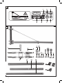
ELENCO COMPONENTI (FIG. B)
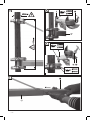
MONTAGGIO (FIG. C)
ATTENZIONE! La struttura di supporto (non in
dotazione), deve essere di dimensioni adeguate
a garantire il perfetto serraggio con le staffe.
Inoltre, essa deve essere in grado di reggere
carichi statici e dinamici, di esercizio e peso
proprio, ed essere adeguatamente vincolata ad
eventuali pareti di edifici. Il dimensionamento
e l’esecuzione della strutura di supporto deve
essere affidata a personale competente; può
diventare pericolosa se fissata ad una struttura
insufficientemente resistente.
ATTENZIONE! Prima di ogni uso dell’attrezza-
tura, verificate la stabilità ed il fissaggio alla
struttura di supporto, nonché la presenza di
eventuali rotture o anomalie visibili.

- 3 -
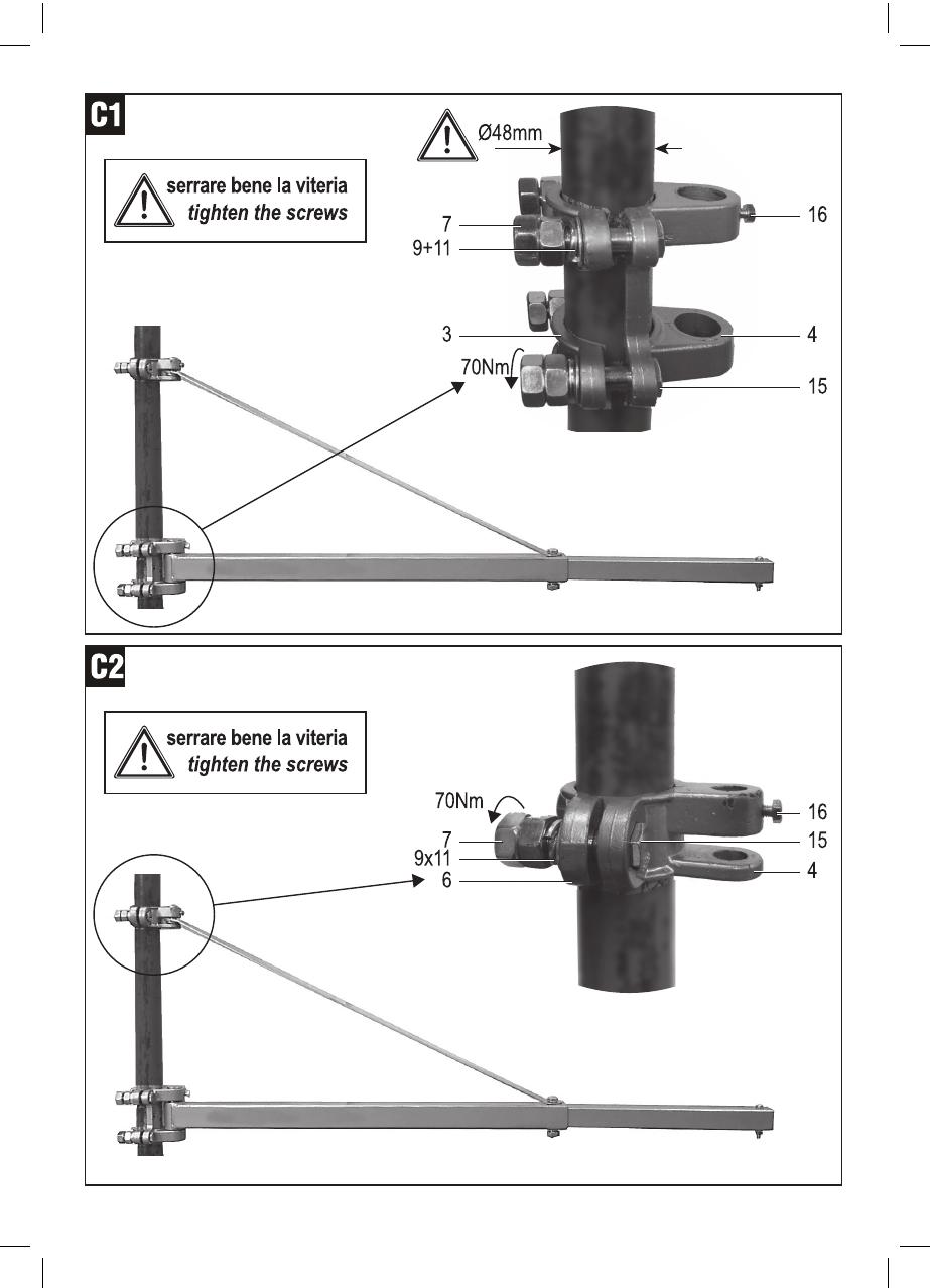
Fig. C1) Fissate la cerniera inferiore (4) con le
due fascette (3) infilando le viti (15), le ron-
delle (9), le rosette elastiche (11) e avvitando
i dadi (7). ( nb: per motivi di sicurezza i dadi
devono essere doppi per ogni vite e la coppia
di serraggio pari a 70Nm)
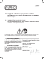
Fig. C2 + Fig. C3) Posizionate la cerniera
superiore (5) in modo che la distanza H tra
le due cerniere sia esattamente 450mm e
fissatela con la stessa procedura usata per la
cerniera inferiore.
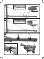
Fig.C4) Posizionate il braccio quadro (17)
all’interno della cerniera inferiore (4) e inserire
il perno (1) opportunamente ingrassato, poi
bloccate il perno avvitando la vite (16).
Fig.C5) Posizionate l’asta di sostegno (19)
all’interno della cerniera superiore(5) e inserire
il perno (2) opportunamente ingrassato, poi
bloccate il perno avvitando la vite (16).
Fig.C6) Infilate il tubo di prolunga (18) con
l’estremità senza foro, all’interno del braccio
quadro (17).
Fig.C7) Collegate l’asta di sostegno (19) con
il braccio quadro (17) ed il tubo di prolunga
(18) inserendo la vite a testa esagonale (14)
attraverso i fori sovrapposti. Inserite la rondella
(9), la rosetta elastica (11) e avviate in modo
sicuro i dadi (7). ( nb: per motivi di sicurezza
i dadi devono essere doppi)
Fig.C8) Sulla estremità libera del tubo di prolun-
ga, montate la vite (13) completa di rondella
piana(10), dentata (12), dado (8), questo per
evitare che il paranco elettrico scivoli fuori.
Fig.C9) Montate il tappo di chiusura 21.
Fig.C10) Montando il paranco elettrico al tubo
di prolunga (18) si devono inserire gli spessori
(20) sotto alle staffe di bloccaggio in modo da
garantire un fissaggio sicuro dello stesso.
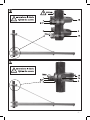
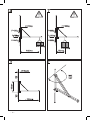
Fig.D1) Con lo sbraccio di 1100 mm ( del pa-
ranco) non si deve sollevare un peso superiore
a 300 kg
Fig.D2) Con lo sbraccio di 750 mm ( del paran-
co) non si deve sollevare un peso superiore
a 600 kg
INSTALLAZIONE E CONDIZIONI PER L’USO (FIG. D)
Fig.D1 -->
Portata massima/sollecitazione ai vincoli
Fig.D2 -->
Portata massima/sollecitazione ai vincoli
Fig.D3 --> Installazione
Fig.D4 --> Angolo di rotazione
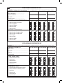
Fig.D5 --> Lista dei controlli periodici
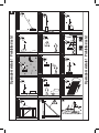
OPERAZIONI VIETATE (FIG. E)
1. Non effettuate tiri inclinati.
2. Non tentate di sollevare carichi vincolati al suolo.
3. Non sollevate carichi agganciati fuori dall’as-
se baricentrico.
4. Non fate pendolare il carico sospeso.
5. Non eseguite manovre di salita o discesa
in presenza di rischio di interferenza con
ostacoli di qualunque natura, come edifici,
linee elettriche, alberi, ecc.
6. Non lasciate carichi appesi.
7. Non effettuate manovre con il carico in
posizione non visibile.
8. Non solevate persone, animali, liquidi e
materiali pericolosi.
9. Non sollevate carichi che fungono da za-
vorra stabilizzante, se il loro sollevamento
compromette l’equilibrio di qualunque altro
oggetto o struttura.
10. Non esponete l’attrezzatura agli agenti at-
mosferici quali pioggia, nebbia, alte e basse
temperature, fulmini e vento.
11. Non utilizzate l’attrezzatura se sono presenti
estranei o veicoli.
12. Non sollevate carichi eccedenti la portata
massima.
13. Non utilizzate l’attrezzatura se questa non é
in perfetta efficienza.
14. Non installate l’attrezzatura su veicoli, strut-
ture mobili, ambienti aggressivi.
PULIZIA E MANUTENZIONE
Pulite regolarmente il braccio orientabile e lu-
brificate i perni delle cerniere ( fig.C4 / fig.C5 ).
GARANZIA
Il prodotto è tutelato a norma di legge contro non
conformità rispetto alle caratteristiche dichiarate
purché sia stato utilizzato esclusivamente nel
modo descritto dalle istruzioni, non sia stato
manomesso in alcun modo, sia stato conser-
vato correttamente, sia stato riparato da tecnici
autorizzati e, ove previsto, siano stati utilizzati
solo ricambi originali.
In caso di utilizzo industriale o professionale
oppure in caso di impiego simile la garanzia ha
validità di 12 mesi.
Per emettere una richies ta di intervento in garan-
zia è necessario presentare la prova di acquisto
al rivenditore o ad centro assistenza autorizzato.

- 4 -
g
IMPORTANT! READ AND CLOSELY FOLLOW
THE INSTRUCTIONS BELOW.
Failure to comply with the warnings and in-
structions may cause serious accidents and/
or injuries.
Strict observance of these warnings together
with the use of personal protective equipment
minimises the risk of accidents but does not
completely rule them out.
Only use this support as described in these
instructions. Do not use it for purposes for
which it was not intended.
Store all warnings and instructions for future
reference.
TECHNICAL CHARACTERISTICS: (FIG. D1/D2)
span I max. load
l1 = 750 mm m1 = 600 kg
l2 = 1,100 mm m2 = 300 kg
Weight: 8 kg
INFORMATION FOR THE USER
The over braced jib crane serves as a support
for an electrical hoisting unit.
The movable arm must be mounted to a well
secured steel bar, with a diameter of 48 mm and
adequate thickness.
This support should only be used for the pur-
poses for which it was intended.
Any other use not expressly indicated in this
manual is to be considered improper and there-
fore prohibited.
The minimum static forces transmitted to the
support structure during work operations are
shown in figure D1/D2. (Warning: the dynamic
stresses that could occur during use could
increase the values of these forces).
Before installing, make sure the area chosen is
sufficiently wide to work safely. Before assem-
bling or dismantling the over braced jib crane,
make sure the surrounding area is secured in
order to minimise the risk of any falling parts
causing damage or injury.
PRELIMINARY OPERATIONS BEFORE
USING AND AFTER EACH INSTALLATION
Before using and after each installation, when
the electric hoist is connected and ready for
use, the whole hoisting system must undergo
the following test. This verification test must
be done by a competent person.
1) do a few up and down cycles without a load
and then a rotation test of 180° to the left
and the right.
2) do a few tests with ever increasing weight
for short distances (max. 20 cm) until you
reach the maximum weight that can be lifted.
Only after these tests can the machine be
used safely.
DESCRIPTION OF MARKS AND SYMBOLS
(FIG. A)
1 WARNING! Falling material hazard.
2 Carefully read the instruction manual before use.
3 A protective helmet is mandatory.
4 Walking or standing under loads or in the
manoeuvring area is prohibited.
USE of the tool is prohibited if there are
people in the manoeuvring area.
5 Product code.
6 Batch number.
7 Do not expose to the rain.
LIST OF COMPONENTS (FIG. B)
ASSEMBLY (FIG. C)
IMPORTANT! The support structure (not pro-
vided), must be of suitable dimensions and
guarantee a perfect grip with the brackets.
Furthermore, it must be able to sustain static,
dynamic and working loads, its own weight and
be suitably secured to building walls. A quali-
fied person must dimension and construct the
support structure; it may become hazardous if
secured to an insufficiently resistant structure.
IMPORTANT! Before using the tool, check the
stability and fastening to the support structure,
and check for any visible breaks or faults.
Fig. C1) Fasten the bottom hinge (4) to the two
bearing clamps (3) inserting the screws (15),
washers (9), spring washers (11) and tighten-
ing the nuts (7). (NB: For safety reasons, the

- 5 -
nuts must be double for each screw and the
tightening torque equal to 70 Nm).
Fig. C2 + Fig. C3) Position the top hinge (5)
so that distance H between the two hinges is
exactly 450 mm and attach it using the same
procedure used for the bottom hinge.
Fig.C4) Place the square arm (17) inside the bot-
tom hinge (4) and insert the suitably greased
pin (1), then lock the pin in by tightening the
screw (16).
Fig.C5) Place the tie rod (19) inside the top hinge
(5) and insert the suitably greased pin (2), then
lock the pin in by tightening the screw (16).
Fig.C6) Slide the extension tube (18), by the
extremity without a hole, inside the square
arm (17).
Fig.C7) Connect the tie rod (19) to the square
arm (17) and the extension tube (18) by in-
serting the hex head screw (14) through the
overlapping holes. Insert the washer (9), the
spring washer (11) and securely fasten the
nuts (7). (NB: For safety reasons, the nuts
must be double)
Fig.C8) On the free end of the extension tube,
place the screw (13) with the flat washer (10),
toothed washer (12), nut (8), to prevent the
electric hoist from sliding out.
Fig.C9) Mount end cap 21.
Fig.C10) When assembling the electric hoisting
unit to the extension tube (18), insert the shims
(20) under the fixing brackets in order to ensure
it is firmly secured.
Fig.D1) The 1,100 mm span (of the hoisting
unit) cannot lift a weight greater than 300 kg
Fig.D2) The 750 mm span (of the hoisting unit)
cannot lift a weight greater than 600 kg
INSTALLATION AND CONDITIONS FOR USE (FIG. D)
Fig.D1 --> Maximum capacity/ stress to the
constraints
Fig.D2 --> Maximum capacity/ stress to the
constraints
Fig.D3 --> Installation
Fig.D4 --> Rotation angle
Fig.D5 --> List of periodic checks
FORBIDDEN OPERATIONS (FIG. E)
1. Do not lift at an angle.
2. Do not attempt to lift loads secured to the
ground.
3. Do not lift loads hooked off-centre.
4. Do not let the suspended load swing.
5. Do not lift or lower if there is a risk of inter-
ference with any type of obstacle such as
buildings, power lines, trees, etc.
6. Do not leave loads hanging.
7. Do not conduct operations when the load is
not visible.
8. Do not lift people, animals, liquids or danger-
ous materials.
9. Do not lift loads that act as stabilising
weights if lifting them jeopardises the bal-
ance of any other object or structure.
10. Do not expose the tool to atmospheric agents
such as rain, fog, high or low temperatures,
lightening or wind.
11. Do not use the tool if there are untrained
people or vehicles present.
12. Do not lift loads that exceed the maximum
capacity.
13. Do not use the tool when not in perfect
operating conditions.
14. Do not install the tool on vehicles, mobile
structures or aggressive environments.
CLEANING AND MAINTENANCE
Regularly clean the movable arm and lubricate
the hinge pins (fig.C4 / fig.C5).
WARRANTY
The product is protected by law against non-
compliance with the declared characteristics
provided it is used only in the manner described
in the instructions, it has not been tampered with
in any way, it has been stored properly, has been
repaired by authorized and, where applicable,
have been used only original spare parts.
In the case of industrial or professional use or
when using such a guarantee is valid for 12
months.
To issue a claim under warranty you must
present proof of purchase to your dealer or
authorized service center.

- 6 -
- 7 -

- 8 -

- 9 -

- 10 -

- 11 -
INSTALLAZIONE E CONDIZIONI PER L’USO
ATTENZIONE! Se anche un solo punto del controllo é negativo, consegnate l’attrezzatura ad un centro autorizzato per un controllo.
LISTA DI CONTROLLO PERIODICO
Nome attrezzatura.................................
Codice attrezzatura...............................
Nr. di lotto............................................
Data di acquisto....................................
CONTROLLO VISIVO ATTREZZATURA
- Controllo ruggine e corrosione
- Controllo piegature
- Controllo saldature
- Controllo rotture
- Controllo usura
CONTROLLO COMPONENTI
- Controllo stato e fissaggio viteria
- Controllo stato e fissaggio dadi
- Controllo perni
- Controllo tiranti
- Controllo copiglie
- Controllo staffe
SI NO SI NO SI NO
DATA E FIRMA DATA E FIRMA DATA E FIRMA
SI NO SI NO SI NO
SI NO SI NO SI NO
SI NO SI NO SI NO
SI NO SI NO SI NO
SI NO SI NO SI NO
SI NO SI NO SI NO
SI NO SI NO SI NO
SI NO SI NO SI NO
SI NO SI NO SI NO
SI NO SI NO SI NO
INSTALLATION AND CONDITIONS FOR USE
IMPORTANT! Even if only one of the above listed check points is negative, take the tool to an authorised service centre for a check.
PERIODIC CHECK LIST
Name of tool......................................................
Tool code..........................................................
Batch no...........................................................
Purchase date...................................................
TOOL VISUAL CHECK
- Check rust and corrosion
- Check bends
- Check welding
- Check breakages
- Check wear
COMPONENT CHECK
- Check condition and fastening of screws
- Check condition and fastening of nuts
- Check pins
- Check tie rods
- Check split pins
- Check brackets
YES NO YES NO YES NO
DATE AND SIGNATURE DATE AND SIGNATURE DATE AND SIGNATURE
YES NO YES NO YES NO
YES NO YES NO YES NO
YES NO YES NO YES NO
YES NO YES NO YES NO
YES NO YES NO YES NO
YES NO YES NO YES NO
YES NO YES NO YES NO
YES NO YES NO YES NO
YES NO YES NO YES NO
YES NO YES NO YES NO
D5

E
Operazioni vietate! Prohibited acts!
Operazioni vietate! Prohibited acts!
-
 1
1
-
 2
2
-
 3
3
-
 4
4
-
 5
5
-
 6
6
-
 7
7
-
 8
8
-
 9
9
-
 10
10
-
 11
11
-
 12
12


em outras línguas
- italiano: Valex 1450554 Manuale del proprietario
- English: Valex 1450554 Owner's manual
Artigos relacionados


Outros documentos
-
Ferm LHM1008 - KT750 Manual do proprietário
-
Beta 8143 Instruções de operação
-
Climbing Technology 2P656 Instruções de operação
-
 Ergodyne 3175 Instruções de operação
-
Focal ISU165 Manual do usuário
-
EINHELL BT-EH 1000 Manual do proprietário
-
Miller LE394757 Manual do proprietário
-
GYS GYSPOT INVERTER PTI.G - 220 V Manual do proprietário
