
1
HYDRAULIC CRIMPING TOOLS
PRESSES HYDRAULIQUES
HYDRAULISCHE PRESSWERKZEUGE
HERRAMIENTAS HIDRAULICAS DE COMPRESION
UTENSILI OLEODINAMICI DA COMPRESSIONE
ENGLISH
FRANÇAIS
DEUTSCH
ESPAÑOL
ITALIANO
05 M 057
OPERATION AND MAINTENANCE MANUAL
NOTICE D'UTILISATION ET ENTRETIEN
BEDIENUNGSANLEITUNG
MANUAL DE USO Y MANTENIMIENTO
MANUALE D'USO E MANUTENZIONE
HT131-U
HT131-UC

2
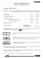
1
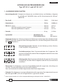
- Tool type
- Outil type
- Handwerkzeug Typ
- Herramienta tipo
- Tipo di utensile
- Year
- Année
- Jahr
- Año
- Anno
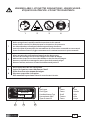
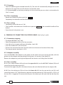
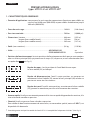
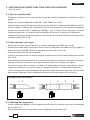
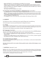
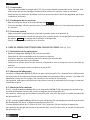
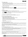
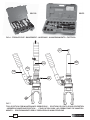
WARNING LABELS - ETIQUETTES SIGNALETIQUES - WARNSCHILDER -
ETIQUETAS DE ATENCION - ETICHETTE D'AVVERTENZA
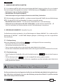
– Before using the tool, carefully read the instructions in this manual.
– Avant d'utiliser cet outil, lire attentivement les instructions de cette notice.
– Vor Inbetriebnahme unbedingt die Bedienungsanleitung durchlesen.
– Antes de utilizar la herramienta, leer atentamente las instrucciones contenidas en este manual.
– Prima di utilizzare l'utensile, leggere attentamente le istruzioni contenute in questo manuale.
– When operating the tool keep hands away from the danger zone.
– Au cours du sertissage, tenir les mains éloignées de la zone de danger.
– Während des Verpressens nicht mit den Händen in den Pressbereich langen.
– Durante su utilización, mantenga las manos fuera de la zona de peligro.
– Durante l'utilizzo, mantenere le mani fuori dalla zona di pericolo.
2
– Do not pump when dies are not in place.
– Insérer les matrices avant d'actionner l'outil.
– Nicht ohne Presseinsatzpaar betatigen.
– No poner en presión sin matrices.
– Non mandare in pressione l'utensile senza le matrici inserite.
3
4
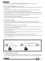
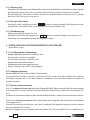
TYPE
FORCE
130 kN
HT131-UC
Made in Italy
2
3
1
2
3
1
23
1
4
- Force
- Force
- Kraft
- Fuerza
- Forza

3
ENGLISH
HYDRAULIC CRIMPING TOOLS
HT131-U and HT131-UC *
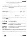
1. GENERAL CHARACTERISTICS
– Application range: is suitable both for compression of electrical connectors on conductors up
to 400 mm
2
(800 MCM) and aluminium conductors up to 300 mm
2
(600 MCM) .
– Crimping force: ........................................................................................................... 130 kN (14.6 sh ton)
– Rated operating pressure: ..................................................................................... 700 bar (10,000 psi)
– Dimensions: length .................................................................................................. 488 mm (19.2 in.)
width with handles closed ........................................................... 149 mm (5.8 in.)
width with handles open ............................................................. 349 mm (13.7 in.)
– Weight (without dies): .............................................................................................. 5,4 kg (11.9 lbs)
– Recommended oil: .............................................................. AGIP ARNICA 22 or
ESSO INVAROL EP22 or equivalent
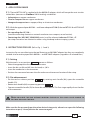
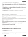
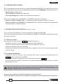
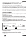
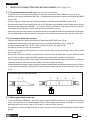
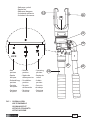
– Operating positions. The three operating positions are identifi ed on the main handle, which
rotates relative to the reference symbol, (see Fig. 1).
Rest position (Handles locked): lock handles together when tool is not
in use.
Release position: close the moveable handle (53) against the main handle
(04), in order to discharge the oil pressure and retract the dies.
Operating position: operate the moveable handle (53), to build up
pressure and close the dies.
– Advancing speed. The tool has two forward speeds of the ram and automatically switches from
a fast advancing speed of dies to a slower crimping speed.
– Safety. The tool is provided with max pressure valve; MPC1 special manometer, is available upon
request to check the correct setting of the valve.
* The HT131-UC tool is the HT131-U tool fi tted with adaptor AU130-C (Ref. to Fig. 2).

4
2. APPLICATION RANGE
2.1) The tool HT131-UC is supplied with the AU130-C adaptor, which will accept the semi-circular
slotted dies (common to Cembre 130 kN tooling) suitable for:
– Indentation on copper conductors
– Circular Compression on copper conductors.
– Hexagonal compression on copper, aldrey or aluminium conductors.
2.2) With the upper adaptor AU130-... and lower adaptor AC130-P, the tool HT131-U or HT131-UC
can accept:
– Pre-rounding dies UP 130-...
(used for converting aluminium sectoral conductor to a compact, round section).
– Containing dies (MV, MVC, MVM, MUA series) and the relevant Indentors PS130-.../E
(to crimp connectors on aluminium cables using the deep indent crimping system).
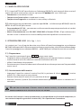
3. INSTRUCTIONS FOR USE (Ref. to Fig. 1, 2 and 3)
Instruction for use are referring to the tool featuring an AU130-C adaptor but they are completely
suitable also for tool equiped with AU130-... and AC130-P adaptors (regardless of selected dies).
3.1) Setting
With the tool is in rest position operate as follows:
– Select the appropriate die set for the connector.
– Insert the die set (88 and 89) into the head, as § 4.3.
– Insert the conductor in the connector.
– Position the connector between the dies and ensure the correct location of the crimp.
3.2) Die advancement
– Set the tool on release position by rotating main handle (04); open the moveable
handle (53).
– Rotate main handle (04) to operating position .
– Operate moveable handle (53) for lower die advancement. This fi rst stage rapidly closes the dies
to the connector.
NEVER PRESSURIZE THE TOOL WITHOUT INSERTING THE DIES AS THIS COULD CAUSE DAMAGE TO
THE TOOL HEAD AND THE RAM.
Make sure the dies are exactly positioned on desired crimp point, otherwise re-open dies following
instructions as per § 3.4 and position the connector again.
ENGLISH

5
ENGLISH
3.3) Crimping
– Continue operating the moveable handle (53). The tool will automatically change over to the
high pressure stage. The ram will advance until the dies meet.
– It is recommended to continue pumping until the maximum pressure valve is activated and a
"click" is heard.
3.4) Dies re-opening
– Rotate main handle to release position .
Completely close handles and the die will retract.
3.5) Rest setting
– Completely retract the ram as § 3.4.
– Close handles and rotate main handle to rest position ; the moveable handle will be
locked.
– Store the tool in the plastic case.
4. CRIMPING OF CONNECTORS ON COPPER CABLES (Ref. to Fig. 2 and 3)
4.1) Connector crimping
– Fit adaptor AU130-C (see § 4.2).
– Select the appropriate die set for the connector.
– Insert die set in to upper and lower die holders (see § 4.3).
– Insert the conductor in the connector.
– Position the connector between the dies and ensure the correct location of the crimp.
– To crimp connector continue as § 3.2.
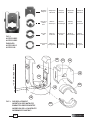
4.2) Adaptor assembly
Insert the AU130-C (90) adaptor in the guides on the U-fork (33) until securely located, with the
grooves on the adaptor corresponding to the locators (34) on the U-fork head (33).
Remove the adaptor by pushing the adaptor off the locators and sliding from the head.
4.3) Dies assembly
4.3.1) Press release button (86) and insert the upper die (88) into the AU130-C adaptor (90) until
secured by the die retaining pin (87).
To remove the upper die, press the release button (86) and slide the die from the adaptor (90).
4.3.2) Press the release pin (30) and insert the lower die (89) into the seat on the ram (28) until
secured by the pin (32). To facilitate this operation an advancement of 15-20 mm (0.59 - 0.79 in.) of
the ram (28) is suggested. To remove the die press the release pin (30) and slide the die from the
ram.

6
5. CRIMPING OF CONNECTORS ON ALUMINIUM CABLES (Ref. to Fig. 4 and 5)
5.1) Pre-rounding conductor (for sectoral cables)
– From the table (Fig. 9, page 42) select the adaptors and pre-rounding dies for the appropriate
conductor size.
– Insert the upper adaptor AU130-... and AC130-P lower adaptor into the head (see § 5.3).
– Insert the pre-rounding die (94) into the AC130-P adaptor (see § 5.4).
– Position the conductor into the pre-rounding die (95) and locate the pre-rounding die (95) in
the adaptor AU130-... (see § 5.4). Ensure that the pre-rounding die is correctly located in the
adapter with it’s upper slot in line with the internal adapter pins.
– Operate the tool until the dies are fully closed.
Release the hydraulic pressure (see § 3.4) and remove the compacted round conductor.
5.2) Connector crimping
– Remove the pre-rounding dies and the adaptor AC130-P from the tool head (see § 5.4).
– From the table (Fig. 9, page 42) select the containing die and indentor recommended for the
conductor size.
– Insert the indentor PS130.../E into the ram (28) (see § 5.4).
– Insert conductor into the connector; locate the connector into the containing die; locate the
containing die in the adaptor (see § 5.4).
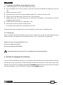
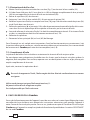
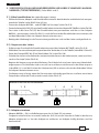
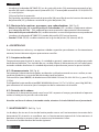
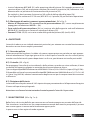
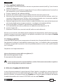
Commence indent crimping from the barrel end for both splices and terminals, following the
sequence shown below.
– For every operation ensure the die is correctly located in the adapter with it’s upper slots in line
with the internal adapter pins.
– Each indenting operation is completed when indentor and die are fully closed;
it is recommended to continue pumping until the maximum pressure valve is activated and a
"click" is heard (see § 3.3).
5.3) Adaptor fi tting and removal
– Insert the upper adaptor AU130-... (98) into the U-fork head (33) until secured by the locators
(34). To remove the adaptor from the U-fork head, push the adaptor from the locators and slide out.
ENGLISH
INDENTING SEQUENCE
1 2
1 4 3 2

7
ENGLISH
– To insert the adaptor AC130-P (91), press the die release pin (30).
Insert the adaptor into the seat of the ram (28), until secured by the retaining pin (32).
To facilitate this operation, an advancement of 15÷20 mm (0.59-0.79 in.) of the ram (28) is sug-
gested. To remove the adaptor, press the die release pin (30) and slide the adaptor from the ram
(28).
5.4) Dies, indentors, pre-rounding dies - fi tting and removal (Ref. to Fig. 5)
– The containing die (96) and upper pre-rounding die (95): are located in the adaptor AU130-...
(98) by grooves in the upper face.
– The lower pre-rounding die (94): is inserted or removed from the adaptor AC130-P (91), by pulling
the release button (92).
– The indentor PS130.../E (93): is inserted into the seat on the ram (28) (see § 4.3.2).
6. WARNING
The tool is robust and requires very little daily maintenance.
Compliance with the following points, should help to maintain the optimum performance of the tool.
6.1) Accurate cleaning
Dust, sand and dirt are a danger for any hydraulic device.
Every day, after use, the tool must be cleaned with a clean cloth, taking care to remove any residual,
especially close to pivots and moveable parts.
6.2) Storage (Ref. to Fig. 6)
When not in use, thetool should be stored and transported in it's case to prevent damage. Follow-
ing cases are available:
– VALP3 plastic case: size 620x380x135 mm (24.4x14.9x5.3 in.), weight 2,5 kg (5.5 lbs).
– VAL130 steel case: size 360x280x48 mm (14.17x11x1.89 in.), weight 3 kg (6.62 lbs), for storage of
the accessories for crimping aluminium connectors.
6.3) Head rotation
For ease of operation, the tool head can rotate through 180°.
Warning: do not attempt to turn the head if the hydraulic circuit is pressurised.
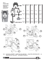
7. MAINTENANCE (Ref. to Fig. 7 and 8)
Air in the hydraulic circuit may aff ect the performance of the tool; e.g. no lower die advancement,
slow advancement of the lower die; lower die pulsating.
In this case proceed as follows:

8
ENGLISH
7.1) To purge air bubbles from hydraulic circuit
a – Hold tool upright in a vice with handles open (Fig. 7).
b – By an hexagonal 2,5 mm key, remove screw (62) and main handle (04) to expose oil reservoir
(03).
c – Remove reservoir cap (01).
d – Operate three or four times the moveable handle (53), to advance the ram (28).
e – Depress pressure release pin (70) until ram is fully retracted.
f – Repeat points (d - e) at least fi ve times, to ensure all air bubbles in the hydraulic circuit are
purged into the reservoir.
g – If the oil level is low, top up as directed in § 7.2.
h – Remove all air from reservoir and fi t cap (01).
i – Assemble main handle (04), and holding screw (62).
If the tool continues to malfunction return the tool for service/repair as detailed in § 8.
7.2) Oil top up
Every six months check the oil level in the reservoir. If necessary, top up the oil level to the top lip
of the reservoir and remove all air from the reservoir, see 7.1, points a, b, c, e, g, h and i.
Always use clean recommended oil, see § 1.
Do not use old or recycled oil.
Do not use hydraulic brake fl uid.
Ensure that disposal of used oil is in accordance with current legislation.
8. RETURN TO Cembre FOR OVERHAUL
In the case of a breakdown contact our Area Agent who will advise you on the problem and give
you the necessary instructions on how to dispatch the tool to our nearest service Centre; if possible,
attach a copy of the Test Certifi cate supplied by Cembre together with the tool or fi ll in and attach
the form available in the “ASSISTANCE” section of the Cembre website.

9
ENGLISH
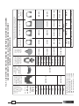
6800040 01 RESERVOIR CAP 1
6380265 ● 02 MAIN HANDLE GRIP 1
6720100 03 OIL RESERVOIR 1
6480043 ● 04
MAIN HANDLE
1
6760014 ● 05 ø 3x4 SPLIT PIN 1
6780105 ● 06 MAIN HANDLE SUPPORT 1
6360260 ★ 07 O-RING 1
6040685 08 GUIDING RING 2
6900621 09 COMPL. SUCTION SCREW 1
6360160 ★ 10 O-RING 1
6740060 ★ 11 3/16" BALL 1
6520765 ★ 12
SUCTION SPRING
1
6160234 13 BODY 1
6740060 ★ 14 3/16" BALL 1
6520765 ★ 15 SUCTION SPRING 1
6740140 ★ 16 9/32" BALL 1
6520180 ★ 17 NO RETURN SPRING 1
6340566 18 BALL SUPPORT 1
6900059 19 M 4x8 SCREW 1
6100020 20 KEY 1
6700250 ▲ 21 ø 36 CIRCLIP 1
6170140 ▲ 22 SPRING COVER 1
6360420 ★ ▲ 23 O-RING 1
6040320 ★ ▲ 24 BACK-UP RING 1
6520620 ▲ 25 RAM RETURN OUTER SPRING 1
6520610 ▲ 26 RAM RETURN INNER SPRING 1
6300040 ▲ 27 RAM SPRING GUIDE 1
6620315 ▲ 28 RAM 1
6522006 ▲ 29 SPRING 1
6620445 ▲ 30 DIE RAM RELEASE PIN 1
6760040 ▲ 31 ø 3x8 SPLIT PIN 1
6620320 ▲ 32 DIE RAMRETAINER PIN 1
6280025 ■ 33 U-FORK HEAD 1
6340630 ■ 34 M10 DOWEL 2
6180800 ■ 35 M10 NUT 2
6100035 36 KEY 1
6900252 37 M 5x14 SCREW 1
6362035 ★ 38 SEAL 1
6362010 ★ 39 SEAL 1
6641140 ★ 40 BACK-UP RING 1
6360240 ★ 41 SEAL 1
6362020 ★ 42 SEAL 1
6620382 43 PUMPING RAM 1
Code N°
Item DESCRIPTION Qty
Code N°
Item DESCRIPTION Qty
6760320 ✚ 44 ø
5x30 SPLIT PIN
1
6780265 ✚ 45
MOVEABLE HANDLE SUPPORT
1
6700100 ★ 46 ø 7 CIRCLIP 2
6700100 ✚ 47 ø 7 CIRCLIP 2
6080060 ✚ 48 MOVEABLE HANDLE BUSH 4
6560420 ✚ 49 MOVEABLE HANDLE PIVOT 1
6560420 50 MOVEABLE HANDLE PIVOT 1
6200030 ✚ 51 MOVEABLE HANDLE LATCH
1
6760280 ✚ 52 ø 4x30 SPLIT PIN 1
6480269 ✚ 53 MOVEABLE HANDLE 1
6380240 ✚ 54 MOVEABLE HANDLE GRIP 1
6232006 55 LABEL (TG. 0356) 1
6650118 56 ø 2,5x3,5 RIVET 2
6232068 57 METAL LABEL (TG. 0268) 1
6760040 ▲ 58 ø 3x8 SPLIT PIN
1
6740020 ★ 59 1/4" BALL 1
6520280 60 SPRING
1
6640205 61 WASHER 1
6900060 62 M 4x8 SCREW 1
6895050 63 MAX PRESSURE VALVE
1
6360160 ★ 64 O-RING 1
6740120 ★ 65 7/32" BALL 1
6600100 66 BALL SUPPORT 1
6520260 67 SPRING 1
6740080 ★ 68 5/16" BALL 1
6340540 69 M 10x8 DOWEL 1
6620120 70 PRESSURE RELEASE PIN 1
6360120 ★ 71 O-RING 1
6040060 ★ 72 BACK-UP RING 1
6080080 73
PRESS. RELEASE PIN BUSH
1
6900280 ✚ 74 M5x18 SCREW 1
6180200 ✚ 75 M5 NUT 1
6340566 76 BALL SUPPORT 1
6520180 ★ 77 NO RETURN SPRING 1
6740140 ★ 78 9/32” BALL 1
6635011 79 PRESSURE RELEASE PIN 1
6520861 80 PRESSURE RELEASE SPRING 1
6340720 81 PRESSURE RELEASE DOWEL 1
6480042 ● COMPLETE MAIN HANDLE
6620316 ▲ COMPLETE RAM
6280026 ■ COMPLETE FORK
6480194 ✚
COMPLETE MOVEABLE HANDLE
6000074 ★ SPARE PARTS PACKAGE
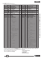
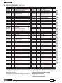
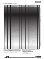
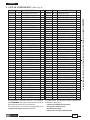
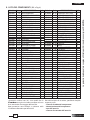
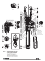
9. PARTS LIST (Ref. to Fig. 8)
The guarantee is void if parts used are not Cembre original spares .
When ordering spare parts always specify the
following:
- code number of item
- name of item
- type of tool
- tool serial number
The items marked () are those
Cembre
recom-
mends replacing if the tool is disassembled. These
items are supplied on request in the
“HT131-U Spare Parts Package”

10
FRANÇAIS
PRESSES HYDRAULIQUES
type HT131-U et HT131-UC*
1. CARACTERISTIQUES GENERALES
– Domaine d'application: conçue pour le sertissage des connecteurs électriques pour câbles en
cuivre jusqu'à 400 mm
2
(800 MCM) et pour câbles en aluminium jusqu'à
300 mm
2
(600 MCM).
– Force de sertissage: .................................................................................................. 130 kN (14.6 sh ton)
– Pression nominale: ................................................................................................... 700 bar (10,000 psi)
– Dimensions: hauteur ............................................................................................... 488 mm (19.2 in.)
largeur (bras mobile fermé) ......................................................... 149 mm (5.8 in.)
largeur (bras mobile ouvert) ....................................................... 349 mm (13.7 in.)
– Poids (sans matrices): ............................................................................................... 5,4 kg (11.9 lbs)
– Huile: ......................................................................................... AGIP ARNICA 22 ou
ESSO INVAROL EP22 équivalent
– Positions de fonctionnement: les trois positions de fonctionnement de la presse sont mention-
nées sur le bras principal (04) qui pivote sous le corps (13) de presse, et sont sélectionnées face
au repère fi xe (voir Fig. 1).
Repère de repos: c'est la position où l'outil doit être au repos.
Le bras mobile (53) est bloqué.
Repère de décompression: l'outil à cette position, en amenant et
maintenant le bras mobile (53) contre le bras principal (04) relache sa
pression et ouvre ainsi les matrices.
Repère de travail: l'outil à cette position, en actionnant le bras mobile
(53), permet la montée en pression et la fermeture des matrices.
– Avance rapide: l'outil passe automatiquement de la vitesse rapide d'approche des matrices, à la
vitesse lente de montée en pression.
– Sécurité: l'outil est pourvu d'une valve de surpression.
Pour vérifi er le bon fonctionnement de cette valve, un manomètre spécial, notre réf. MPC1, est
disponible à la demande.
* Cette désignation indique l’ensemble de l’outil HT131-U complété de l'adaptateur AU130-C (Voir Fig. 2).

11
FRANÇAIS
2. DOMAINE D’APPLICATION
2.1) L’équipement standard de l’outil, comprend l’adaptateur AU130-C avec lequel il peut recevoir
divers types de matrices (communes également aux autres outils Cembre de 130 kN) destinées au:
– Poinçonnage sur câble cuivre.
– Sertissage Semi-circulaire sur câble cuivre.
– Sertissage Hexagonal sur câble cuivre, almélec ou aluminium.
2.2) Avec les adaptateurs types AU130-... et AC130 P, l’outil peut recevoir les:
– Matrices de Mise au Rond UP130-..., ramenant les câbles sectoraux à la forme circulaire.
– Matrices Coquille séries MV, MVM, et les Poinçons PS130-.../E réalisant un poinçonnage profond,
matrice fermée, sur câble aluminium.
3. INSTRUCTIONS D’UTILISATION (Voir Fig. 1, 2 et 3)
Ces instructions font référence à la presse equipée de l’adaptateur AU130-C.
Elles sont néanmoins identiques avec les adaptateurs AU130-... et AC130 P (à l’exception des types
de matrices utilisées).
3.1) Mise en service
Avec l’outil en position de repos procéder comme suit:
– Prendre les matrices à utiliser selon le type de sertissage à eff ectuer.
– Insérer les matrices (88 et 89) dans la tête selon les indications du § 4.3.
– Insérer le conducteur dans le connecteur.
– Positionner ce dernier entre les deux matrices en alignant la zone à sertir avec l'empreinte des
matrices mêmes.
3.2) Avance des matrices
– Empoigner l'outil et pivoter le bras principal (04) jusqu'à la position de décompression
; le bras mobile (53) sera libéré.
– Pivoter ensuite le bras principal (04) jusqu'à la position de travail .
– En actionnant le bras mobile (53) le piston (28) amène rapidement les deux matrices au contact
du connecteur à sertir.
NE JAMAIS METTRE L'OUTIL SOUS PRESSION SANS QUE LES MATRICES NE SOIENT INSEREES, CELA
POURRAIT ENDOMMAGER LES SIEGES DE LA TETE ET DU PISTON.
S’assurer que les matrices sont bien positionnées sur la zone à sertir.
Dans le cas contraire, le desserrer en suivant les instructions du § 3.4 et repositionner le connecteur.

12
FRANÇAIS
3.3) Sertissage
– Poursuivre la manœuvre du bras mobile.
On passera automatiquement de la vitesse rapide à la lente; le piston montera progressivement
jusqu'au contact des matrices.
– Il est conseillé de continuer à pomper jusqu'à l'intervention de la valve de surpression (on doit ù
entendre un léger "clic").
3.4) Réouverture des matrices
– Faire pivoter le bras principal (04) dans la position de décompression .
Refermer à fond le bras mobile, on aura le retour du piston, et par conséquent l'ouverture des
matrices.
3.5) Rangement
– Faire descendre complètement le piston en suivant les indications du § 3.4.
– En maintenant fermé à fond les bras, pivoter ensuite le bras principal jusqu'à la position de repos
; le bras mobile sera ainsi bloqué par le loquet (51).
– Ranger l'outil dans son coff ret.
4. SERTISSAGE SUR CONNECTEURS POUR CABLES EN CUIVRE
(Voir Fig. 2 et 3)
4.1) Exécution des sertissages
– Monter l’adaptateur AU130 -C (90) (voir § 4.2).
– Prendre les matrices à utiliser selon les indications du catalogue.
– Insérer les matrices à leur place (voir § 4.3).
– Insérer le conducteur dans le connecteur à utiliser.
– Positionner ce dernier entre les deux matrices en faisant coincider la zone à sertir face à l’empreinte
des matrices.
– Après celà, opérer selon les indications du § 3.2.
4.2) Montage de l'adaptateur
– Insérer l’adaptateur AU130-C (90) dans les guides de la fourche (33) et le pousser jusqu’à son
blocage, par les billes (34).
– Pour le démonter pousser avec force jusqu’au dégagement des billes (34).
4.3) Montage des matrices
4.3.1) Insérer la matrice supérieure (88) dans l’adaptateur AU130-C (90) en appuyant sur le poussoir
(86) et la pousser jusqu’à ce que l’ergot (87) la verrouille.
Pour la dégager appuyer sur le poussoir (86) et la faire glisser.
4.3.2) Insérer la matrice inférieure (89) dans les guides du piston (28) en appuyant sur le poussoir
(30) et la pousser jusqu’à ce que l’ergot (32) la vérouille.
Cette opération est facilitée par l'avancement de 15-20 mm (0.59-0.79 in.) du piston (28).
Pour la dégager appuyer sur le poussoir (30) et la faire glisser.

13
5. SERTISSAGE SUR CONNECTEURS POUR CABLES EN ALUMINIUM
(Voir Fig. 4 et 5)
5.1) Mise au rond du câble
– Prendre les accessoires et les matrices de mise au rond selon les indications du tableau en Fig. 9
page 42.
– Monter sur la tête les adaptateurs AU130-... et AC 130-P (voir § 5.3).
– Insérer la partie mobile (94) de la matrice de mise au rond dans l'adaptateur AC130-P (voir § 5.4).
– Insérer le câble à l’intérieur de la partie fi xe (95) de la matrice de mise au rond et positionner
ensuite cette dernière dans l'adaptateur AU130-... (voir § 5.4) en faisant coïncider la rainure
supérieure présente sur la matrice avec les goupilles localisées à l'intérieur de l'adaptateur.
– Actionner l’outil jusqu’à porter au contact les matrices de mise au rond, relacher ensuite la pression
et libérer le câble (voir § 3.4).
5.2) Exécution des sertissages
– Enlever de la tête les matrices de mise au rond et l'adaptateur AC130-P (voir § 5.4).
– Prendre l'ensemble Matrice-Poinçon à utiliser selon les indications du tableau en Fig. 9, page 42.
– Insérer le poinçon PS130.../E dans le logement du piston (28) (voir § 5.4).
– Insérer le conducteur dans le connecteur.
– Insérer le connecteur dans la matrice coquille et positionner ensuite cette dernière dans la tête
(voir § 5.4).
En actionnant l'outil commencer à sertir le connecteur en partant, pour les manchons, de l'extré-
mité vers l’intérieur et pour les cosses de l'extrémité arrière vers la plage (voir fi gure).
Positionner chaque fois la matrice à l'intérieur de l'adaptateur en faisant coïncider les rainures
supérieures présentes sur la matrice avec les goupilles localisées à l'intérieur de l'adaptateur.
– La fi n de chaque sertissage est obtenue dès le contact du poinçon avec la matrice: il est conseillé
de continuer à pomper jusqu’àu déclenchement de la valve de surpression (voir § 3.3).
5.3) Montage des accessoires
– Insérer l’adaptateur AU130-...dans les guides de la fourche (33) et le pousser jusqu’à son blocage
par les billes (34).
Pour le démonter pousser avec force jusqu’au dégagement des billes (34).
FRANÇAIS
SEQUENCE DES SERTISSAGES
1 2
1 4 3 2

14
FRANÇAIS
– Insérer l’adaptateur AC130-P dans les guides du piston (28) en appuyant sur le poussoir inférieur
(30) et le pousser jusqu'à son blocage par l'ergot (32). Cette opération est facilitée par l'avancement
de 15-20 mm (0.59-0.79 in.) du piston (28).
Pour le démonter, appuyer sur le poussoir (30) et le faire glisser.
5.4) Montage des matrices, des poinçons et des matrices de mise au rond (Voir Fig. 5)
– Matrice coquille (96) ou partie fi xe de matrice de mise au rond (95): elles sont simplement
appuyées dans l’adaptateur AU130-... (98) et peuvent être directement insérées ou dégagées.
– Partie mobile de matrice de mise au rond (94): elle est placée ou retirée du logement de l’adap-
tateur AC130-P (91) en tirant le loquet (92).
– Poinçon PS130.../E (93): il est placée dans les guides du piston (28) (Voir § 4.3.2).
6. PRECAUTIONS
Cet outil est robuste et ne nécessite aucune préoccupation ou entretien particulier. Les recomman-
dations qui suivent sont néanmoins souhaitables pour assurer une longévité optimum:
6.1) Nettoyage élémentaire
Veiller à protéger l'outil de la poussière, du sable et de la boue qui sont un danger à tout système
hydraulique. Chaque jour après utilisation, l'outil doit être nettoyé à l'aide d'un chiff on propre, tout
particulièrement aux endroits de pièces mobiles.
6.2) Rangement (Voir Fig. 6)
Il est de bonne règle de remettre l'outil dans son coff ret, fermé, après usage, en protection des
chocs et de la poussière.
Ce coff ret type VALP3 a comme dimensions 620x380xh135 mm (24.4x14.9x5.3 in.) et un poids de
2,5 kg (5.5 lbs).
La coff ret type VAL130 dimensions 360x280x48 mm (14.17x11x1.89 in.), poids 3 kg (6.62 lbs) est
adapté pour contenir les accessoires pour le sertissage des connecteurs en aluminium.
6.3) Rotation de la tête
La tête de l'outil pivote de 180° par rapport au corps, permettant à l'utilisateur de travailler dans la
meilleure position.
Attention: ne pas forcer la rotation de la tête, lorsque le circuit hydraulique est sous pression.
7. ENTRETIEN (Voir Fig. 7 et 8)
Le seul problème pouvant être rencontré parfois, nécessitant une intervention, est la présence d'une
bulle d'air dans le circuit hydraulique.
Cet incident est caractérisé par un mauvais fonctionnement de l'outil: dans l'action de montée en
pression, soit la matrice inférieure ne monte pas, soit elle progresse trés lentement, soit elle monte
et redescent pulsativement.
Dans ce cas, il est nécessaire de procéder de la façon suivante:

15
FRANÇAIS
7.1) Elimination de bulles d'air
a – Mettre l'outil en position verticale dans un étau (Fig. 7) en écartant le bras mobile (53).
b – A l'aide d'une clé 6 pans de 2,5 mm, ôter la vis (62) et dégager complètement le bras principal
(04) laissant apparaître le réservoir d'huile en caoutchouc (03).
c – Retirer le capuchon (01) du réservoir.
d – Actionner 3 ou 4 fois le bras mobile (53), faisant avancer le piston (28).
e – Relâcher la pression d'huile, en compressant l'axe (70) jusqu'à la rétraction totale du piston (28)
et de l'huile dans son réservoir.
f – Refaire les opérations (d - e) au moins 5 fois, afi n de permettre aux éventuelles bulles d'air conte-
nues dans le circuit hydraulique d'être rejetées et évacuées par le réservoir d'huile.
g – Avant de refermer le réservoir d'huile, l'air doit être complètement évacué. Si le niveau d'huile
est bas, un complément doit être fait comme mentionné au § 7.2.
h – Refermer le capuchon.
i – Remonter le bras principal (04) et la vis (62) de blocage.
Dans l'éventuel cas où, malgré cette intervention, l'outil ne fonctionnerait pas correctement, (soit
la matrice inférieure ne monte pas, soit elle monte et rédescent pulsativement) il est recommandé
de le retourner à Cembre pour une révision complète (voir § 8).
7.2) Complément d'huile
La présence de bulles d'air est évitée en maintenant le réservoir d'huile toujours plein.
Par conséquent nous préconisons de vérifi er tous les 6 mois, que le réservoir soit plein, et dans la
négative, de le compléter. Pour ce faire, reportez vous aux descriptions ci dessus: a, b, c, d et e, puis
emplir complètement le réservoir.
Après cela, terminer les opérations h et i.
En cas de changement d' huile, l'huile usagée doit être éliminée conformément aux normes
en vigueur.
Utiliser exclusivement un type d'huile mentionné au § 1.
Ne jamais utiliser d'huile usagée ou recyclée.
Il est indispensable que l'huile soit neuve.
8. ENVOI EN REVISION A Cembre
En cas de dysfonctionnement de l’appareil, merci de vous adresser à notre Agent Régional qui vous
conseillera et le cas échéant vous donnera les instructions nécessaires pour envoyer l’appareil à
notre Centre de Service le plus proche. Dans ce cas, joindre une copie du Certifi cat d’Essai livré par
Cembre avec l’appareil ou remplir et joindre le formulaire disponible dans la section “ASSISTANCE”
du site web Cembre.

16
FRANÇAIS
N° Code Pièce
DENOMINATION
Q.té N° Code
Pièce
DENOMINATION
Q.té
6800040 01 CAPUCHON DE RESERVOIR 1
6380265 ● 02 POIGNEE BRAS MOBILE 1
6720100 03 RESERVOIR 1
6480043 ● 04 BRAS PRINCIPAL 1
6760014 ● 05 FICHE ø 3x4 1
6780105 ● 06 EMBASE BRAS PRINCIPAL 1
6360260 ★ 07 JOINT TORIQUE 1
6040685 08 ANNEAU GUIDE 2
6900621 09 VIS ASPIRATION 1
6360160 ★ 10 JOINT TORIQUE 1
6740060 ★ 11 BILLE 3/16" 1
6520765 ★ 12 RESSORT ASPIRATION 1
6160234 13 CORPS 1
6740060 ★ 14 BILLE 3/16" 1
6520765 ★ 15 RESSORT ASPIRATION 1
6740140 ★ 16 BILLE 9/32" 1
6520180 ★ 17 RESSORT ANTI-RETOUR 1
6340566 18 CLIQUET PORTE BILLE 1
6900059 19 VIS M 4x8 1
6100020 20 CLAVETTE 1
6700250 ▲ 21 ANEAU ELASTIQUE ø 36 1
6170140 ▲ 22 COUVERCLE RESSORT 1
6360420 ★▲ 23 JOINT TORIQUE 1
6040320 ★▲ 24 ANNEAU BK 1
6520620 ▲ 25 RESSORT EXT.RAPPEL PISTON 1
6520610 ▲ 26 RESSORT INT.RAPPEL PISTON 1
6300040 ▲ 27 COUSSINET 1
6620315 ▲ 28 PISTON 1
6522006 ▲ 29 RESSORT 1
6620445 ▲ 30 AXE DE DEBLOQ.MATR./TETE 1
6760040 ▲ 31 FICHE ø 3x8 1
6620320 ▲ 32 AXE DE VERROUIL.MATR./TETE 1
6280025 ■ 33 CHAPE EN “U” 1
6340630 ■ 34 VIS SANS TETE M10 2
6180800 ■ 35 ECROU M10 2
6100035 36 CLAVETTE 1
6900252
37 VIS M 5x14 1
6362035 ★ 38 JOINT TORIQUE 1
6362010 ★ 39 JOINT R6 1
6641140 ★ 40 ANNEAU BK - R6 1
6360240 ★ 41 JOINT TORIQUE 1
6362020 ★ 42 JOINT JF 1
6620382 43 PISTON 1
6760320 ✚ 44 FICHE
ø 5x30
1
6780265 ✚ 45 EMBASE BRAS MOBILE 1
6700100 ★ 46 ANEAU ELASTIQUE ø 7 2
6700100 ✚ 47 ANEAU ELASTIQUE ø 7 2
6080060 ✚ 48 ANNEAU BRAS MOBILE 4
6560420 ✚ 49 AXE BRAS MOBILE 1
6560420 50 AXE BRAS MOBILE 1
6200030 ✚ 51 LOQUET BRAS MOBILE
1
6760280 ✚ 52 FICHE ø 4x30 1
6480269 ✚ 53 BRAS MOBILE 1
6380240 ✚ 54
POIGNEE
BRAS MOBILE 1
6232006 55 ETIQUETTE (TG. 0356) 1
6650118 56 RIVET ø 2,5 x 3,5 2
6232068 57 PLAQUETTE (TG. 0268) 1
6760040 ▲ 58 FICHE ø 3x8
1
6740020 ★ 59 BILLE 1/4" 1
6520280 60
RESSORT
1
6640205 61 RONDELLE 1
6900060 62 VIS M 4x8 1
6895050 63 VALVE
COMPLETE
1
6360160 ★ 64 JOINT TORIQUE 1
6740120 ★ 65 BILLE 7/32" 1
6600100 66 CLIQUET PORTE BILLE 1
6520260 67 RESSORT DE DECOMPRESS. 1
6740080 ★ 68 BILLE 5/16" 1
6340540 69 VIS SANS TETE M 10x8 1
6620120 70
AXE DE DECOMPRESSION
1
6360120 ★ 71 JOINT TORIQUE 1
6040060 ★ 72 ANNEAU BK 1
6080080 73
ANNEAU AXE DE RETOUR PRESS.
1
6900280 ✚ 74 VIS M 5x18 1
6180200 ✚ 75 ECROU M5 1
6340566 76 CLIQUET PORTE BILLE 1
6520180 ★ 77 RESSORT ANTI-RETOUR 1
6740140 ★ 78 BILLE 9/32” 1
6635011 79 SOMMET DE DECOMPRES. 1
6520861 80 RESSORT DE DECOMPRESS. 1
6340720 81 GOUPILLE DE DECOMPRESS. 1
6480042 ● BRAS PRINC.COMPLET
6620316 ▲ PISTON COMPLET
6280026 ■ CHAPE EN “U” COMPLETE
6480194 ✚ BRAS MOBILE COMPLET
6000074 ★ PAQUET RECHANGE
9. PIECES DETACHEES (Voir Fig. 8)
La garantie perd tout eff et en cas d'emploi de pièces détachées diff érentes des pièces d'origine Cembre.
Les éléments accompagnés d'un () sont ceux que
Cembre
recommande de remplacer en cas de
démontage de l'outil.
Ces éléments sont fournis sur demande dans le
“Paquet Rechange pour HT131-U”.
Lors de la commande de pièces détachées, veuillez
indiquer toujours les éléments suivants:
- numéro de code article de la pièce
- désignation de la pièce
- type d'outil
- numéro de série de l'outil

17
HYDRAULISCHE PRESSWERKZEUGE
Typ HT131-U und HT131-UC*
1. ALLGEMEINE EIGENSCHAFTEN
– Anwendungsbereich: Geeignet zum Verpressen von Kabelschuhen und Verbidern, allgemein
bis auf 400 mm
2
(800 MCM) Leiter und für Aluminiumeiter bis 300 mm
2
(600 MCM).
– Presskraft: ..................................................................................................................... 130 kN (14.6 sh ton)
– Arbeitsdruck: ............................................................................................................... 700 bar (10,000 psi)
– Abmasse: Länge ........................................................................................................ 488 mm (19.2 in.)
Breite bei geschlossenem Pumparm ............................................. 149 mm (5.8 in.)
Breite bei geöff netem Pumparm .................................................... 349 mm (13.7 in.)
– Gewicht: ........................................................................................................................ 5,4 kg (11.9 lbs)
– Hydrauliköl: ........................................................................... AGIP ARNICA 22 oder
ESSO INVAROL EP22 oder ähnlich
– Arbeitspositionen: Die 3 Arbeitspositionen des Werkzeuges werden durch den drehbaren Hand-
griff (04) eingestellt. Die gewünschte Arbeitsoperation muss mit dem Piktogramm übereinstim-
men (siehe Bild 1).
Ruhestellungsposition: Befi ndet sich das Werkzeug in diese Position,
ist der Pumparm (53) geschlossen.
Druckablassposition: Beim Zusammendrücken des Pumparmes (56)
mit dem Handgriff (04) wird der Öldruck abgebaut und die Presseinsätze
fahren auseinander.
Arbeitsposition: Beim Zusammendrücken des Pumparmes (53) mit dem
Handgriff (04) wird der Öldruck abgebaut und die Presseinsätze fahren
zusammen.
– Eilvorschub. Das Werkzeug ist mit einer Doppelkolbenhydraulik ausgerüstet, die anfangs ein
schnelles Zusammenfahren der Presseinsätze ermöglicht.
Dann wird automatisch auf den langsameren Arbeitshub umgeschaltet.
– Sicherheit. Das Werkzeug ist mit einem Überdruckventil ausgestattet. Der Arbeitsdruck kann mit
dem Messgerät MPC1, das auf Anfrage lieferbar ist, gemessen werden.
* Dieser Hinweis bezieht sich auf das komplette Werkzeug mit Adapter AU130-C (siehe Bild 2).
DEUTSCH

18
2. ANWENDUNGSMÖGLICHKEITEN
2.1) Das Werkzeug HT131-UC wird mit dem Adapter AU130-C ergänzt und kann für ver-schiedene
Presseinsatztypen (kompatibel zu anderen 130 kN Werkzeug von Cembre) verwendet werden:
– Kerbverpressung von Kupferverbindern.
– Runddrücken von Kupferverbindern.
– Sechskantverpressung von Kupfer, Aluminium und Aldrey, Verbindern.
2.2) Mit dem oberen Adapter AU130-... und dem unteren Adapter AC130-P, können die Werkzeuge
HT131-U oder HT131-UC mit folgenden Einsätzen verwendet werden:
– Runddrückmatrizen UP130-... für Aluminium Sektorkabel (ein- und mehrdrähtig).
– Haltematrizen (wie die Serien MV, MVC, MVM, MUA) und die Kerbeinsätze PS130- ... /E
(um Pressverbinder auf Aluminiumleiter mit der Tiefnutkerbung zu verpressen).
3. BEDIENUNGSHINWEISE (Siehe Bild 2 und 3)
Die Bedienungsanleitung bezieht sich auf Werkzeuge mit Adapter AU130-C. Sie ist aber auch für
Werkzeuge mit AU130-... und AC130-P Adapter geeignet (unabhängig von den ausgewählten
Presseinsätzen).
3.1) Vorbereitung
Wenn das Werkzeug in Ruhestellung ist, sind folgende Schritte notwending:
– Passenden Presseinsatz auswählen.
– Presseinsätze einsetzen wie in Pkt. 4.3.
– Den zu verpressenden Leiter in den Verbinder oder Kabelschuh einlegen.
– Positionieren Sie den Verbinder oder Kabelschuh an der vorgeschriebenen Position am Presseinsatz.
3.2) Positionierung
– Durch Drehen des Handgriff es (04) in die Druckablassposition öff net sich der Pumparm
(53).
– Für die Arbeitsposition muss der Handgriff (04) weiter gedreht werden.
– In dieser Position kann der Kolben (28) etwas vorgefahren und der Verbinder oder Kabelschuh
exakt positioniert werden.
SETZEN SIE NIEMALS DAS WERKZEUG OHNE DIE PRESSEINSÄTZE UNTER DRUCK.
DAS KÖNNTE ZU BESCHÄDIGUNGEN DES KOPF- UND KOLBENSITZES FÜHREN.
Die Presseinsätze müssen in die gewünschte Position am Verbinder oder Kabelschuh gebracht wer-
den. Sollte diese nicht korrekt sein, muss das Werkzeug entsprechend Punkt 3.4, geöff net werden
und es kann neu positioniert werden.
DEUTSCH

19
DEUTSCH
3.3) Verpressung
– Pumparm (56) betätigen, der Kolben fährt schnell vor. Sobald der Druckaufbau erfolgt, schaltet
das Werkzeug automatisch um. Num fahren die Presseinsätze fahren langsam zusammen.
– Bei Erreichen des maximalen Druckes schaltet das Überdruckventil automatisch ab, welches
durch ein "Klick" akustisch zu hören ist.
3.4) Presseinsätze lösen
– Handgriff in die Druckablassposition drehen und den Handgriff und Pumparm zusam-
mendrücken. Der Kolben fährt zurück und die Presseinsätze öff nen sich.
3.5) Nachbereitung
– Kolben zurückfahren entspr. Pkt. 3.4.
– Handgriff in die Ruhestellungsposition drehen und den Pumparm einrasten lassen.
– Werkzeug in die dazugehörige Verpackungseinheit legen.
4. VERPRESSEN VON KUPFERVERBINDERN BEI KUPFERKABEL
(Siehe Bild 2 und 3)
4.1) Ausführung der Verbindung
– Adapter AU130-C montieren (siehe Pkt. 4.2).
– Passende Presseinsätze auswählen.
– Presseinsätze einsetzen (siehe Pkt. 4.3).
– Kabel in den Verbinder einlegen.
– Werkzeug entsprechend positionieren.
– Weiter verfahren wie in Pkt. 3.2 angegeben.
4.2) Adapter einsetzen
Adapter AU130-C (90) in die U-Gabel (33) einsetzen.
Die gewünschte Position ist erreicht, wenn der Stift (34) an der Seite der U-Gabel (33) in die Nut
am Adapter eingerastet ist. Um den Adapter zu entfernen, muss man den Adapter drücken und
ihn herausziehen.
4.3) Presseinsätze einsetzen
4.3.1) Den oberen Presseinsatz (88) in den Adapter AU130-C (90) einsetzen bis der Presseinsatzhalter
(87) eingerastet ist (zum Lösen den Druckknopf (86) drücken, damit sich der Presseinsatzhalter (87)
löst).
Um den Presseinsatz zu entfernen, den Druckknopf (86) drücken, um den Presseinsatzhalter zu lösen.
4.3.2) Den unteren Presseinsatz (89) in den Kolben (28) einlegen bis der untere Presseinsatzhalter
(32) eingerastet ist.
Um den Presseinsatz zu entfernen, muss der Druckknopf (30) gedrückt werden, der den unteren
Presseinsatzhalter (32) auslöst.
Bei dieser Tätigkeit ist es von Vorteil, wenn der Kolben (28) 15-20 mm (0.59-0.79 in.) vorgefahren ist.

20
DEUTSCH
5. VERPRESSEN VON ALUMINIUMVERBINDERN UND KABELSCHUHEN BEI ALUMINI-
UMKABEL (TIEFNUTKERBUNG) (Siehe Bild 4 und 5)
5.1) Kabel runddrücken (bei sektorförmigen Leitern)
– Wähle die Matrize, Adapter und Runddrückeinsätze für den Verbinder und Kabelschuh entspre-
chend der Tabelle (siehe Bild 9 Seite 42) aus.
– Fixiere den Adapter AU130-... und AC130-P im Presskopf (siehe Pkt. 5.3).
– Setze das bewegliche Teil (94) von dem Runddrückeinsatz in den Adapter AC130-P ein (siehe Pkt 5.4).
– Den Leiter in das feste Teil (95) des Runddrückeinsatz positionieren und dies in den Adapter
AU130-... positionieren (siehe Pkt 5.4). Es ist auf die Position der Runddrückeinsatz zu achten, die
mit den federnden Stiften im Adapter übereinstimmen muss.
– Betätige das Werkzeug bis die Presseinsätze geschlossen sind und der Leiter rund gedrückt ist.
5.2) Verpressen des Leiters
– Entferne vom Presskopf die Runddrückeinsätze und den Adapter AC130-P (siehe Pkt. 5.4).
– Wähle den Presseinsatzstempel entsprechend des Verbinders aus der Tabelle (siehe Bild 9 Seite 42).
– Setze den Stempel PS130.../E auf den Kolben (28) (siehe Pkt. 5.4).
– Schiebe den Leiter in den Verbinder und positioniere diesen in der Haltematrize, sowie anschlies-
send im Presskopf (siehe Pkt. 5.4).
Beginne die Verpressung mit dem Werkzeug. Der Kabelschuh wird vom Leiter zum Kabelschuh-
auge verpresst. Ein Verbinder wird zu erst aussen und dann anschliessend in der Mitte verpresst
(siehe Bild). Es ist auf die Position der Haltematrize (96) zu achten, die mit den federnden Stiften
im Adapter übereinstimmen muss.
– Die Verpressung ist fertig, wenn die Presseinsätze vollständig geschlossen sind bzw. wenn beim
Pumpen der maximale Druck erreicht wurde (siehe Pkt. 3.3).
5.3) Adapter einsetzen
– Adapter AU130-... (98) in die Befestigung an der U-Gabel (33) einsetzen.
Die gewünschte Position ist erreicht, wenn der Stift (34) an der Seite der U-Gabel in die Nut am
Adapter eingerastet ist. Um den Adapter zu entfernen, am Adapter kräftig drücken und ihn
herausziehen.
REIHENFOLGE DER TIEFNUTKERBUNG
1 2
1 4 3 2
A página está carregando...
A página está carregando...
A página está carregando...
A página está carregando...
A página está carregando...
A página está carregando...
A página está carregando...
A página está carregando...
A página está carregando...
A página está carregando...
A página está carregando...
A página está carregando...
A página está carregando...
A página está carregando...
A página está carregando...
A página está carregando...
A página está carregando...
A página está carregando...
A página está carregando...
A página está carregando...
A página está carregando...
A página está carregando...
A página está carregando...
A página está carregando...
-
 1
1
-
 2
2
-
 3
3
-
 4
4
-
 5
5
-
 6
6
-
 7
7
-
 8
8
-
 9
9
-
 10
10
-
 11
11
-
 12
12
-
 13
13
-
 14
14
-
 15
15
-
 16
16
-
 17
17
-
 18
18
-
 19
19
-
 20
20
-
 21
21
-
 22
22
-
 23
23
-
 24
24
-
 25
25
-
 26
26
-
 27
27
-
 28
28
-
 29
29
-
 30
30
-
 31
31
-
 32
32
-
 33
33
-
 34
34
-
 35
35
-
 36
36
-
 37
37
-
 38
38
-
 39
39
-
 40
40
-
 41
41
-
 42
42
-
 43
43
-
 44
44


em outras línguas
- español: Cembre HT131-UC Manual de usuario
- français: Cembre HT131-UC Manuel utilisateur
- italiano: Cembre HT131-UC Manuale utente
- Deutsch: Cembre HT131-UC Benutzerhandbuch
Artigos relacionados
-
Cembre HT45-E Manual do usuário
-
-
Cembre HT131-C Manual do usuário
-
-
-
-
-
-
-
Outros documentos
-
Makita Nibbler JN1601 Manual do usuário
-
Beta 1609C/C5 Instruções de operação
-
Klein Tools VDV212-008-SEN Instruções de operação
-
NovoPress ACO103 Manual do usuário
-
NovoPress ACO203 Manual do usuário
-
-
Klein Tools VDV226-011-SEN Instruções de operação
-
Hilti DS-W 10.5 Instruções de operação
-
MasterCool 71700 Instruções de operação
-
Edision 216301 COMPRESSION TOOL Manual do usuário