
1
HYDRAULIC CRIMPING TOOL
PRESSE HYDRAULIQUE
HYDRAULISCHES PRESSWERKZEUG
HERRAMIENTA HIDRAULICA DE COMPRESION
UTENSILE OLEODINAMICO DA COMPRESSIONE
HT131-C
ENGLISH
FRANÇAIS
DEUTSCH
ESPAÑOL
ITALIANO
OPERATION AND MAINTENANCE MANUAL
NOTICE D'UTILISATION ET ENTRETIEN
BEDIENUNGSANLEITUNG
MANUAL DE USO Y MANTENIMIENTO
MANUALE D'USO E MANUTENZIONE
14 M 090

2
1
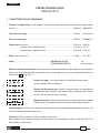
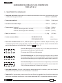
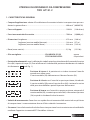
- Tool type
- Outil type
- Handwerkzeug Typ
- Herramienta tipo
- Tipo di utensile
- Year
- Année
- Jahr
- Año
- Anno
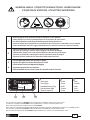
– Before using the tool, carefully read the instructions in this manual.
– Avant d'utiliser cet outil, lire attentivement les instructions de cette notice.
– Vor Inbetriebnahme unbedingt die Bedienungsanleitung durchlesen.
– Antes de utilizar la herramienta, leer atentamente las instrucciones contenidas en este manual.
– Prima di utilizzare l'utensile, leggere attentamente le istruzioni contenute in questo manuale.
– When operating the tool keep hands away from the danger zone.
– Au cours du sertissage, tenir les mains éloignées de la zone de danger.
– Während des Verpressens nicht mit den Händen in den Pressbereich langen.
– Durante su utilización, mantenga las manos fuera de la zona de peligro.
– Durante l'utilizzo, mantenere le mani fuori dalla zona di pericolo.
2
– Do not operate when dies are not in place.
– Insérer les matrices avant d’actionner l’outil.
– Nicht ohne Presseinsatzpaar betätigen.
– No poner en presión sin matrices.
– Non mandare in pressione l’utensile senza le matrici inserite.
3
4
TYPE
FORCE
130 kN
HT131-C
Made in Italy
2 3
1
2
3
1
- Force
- Force
- Kraft
- Fuerza
- Forza
1 2 3
4
This manual is the property of Cembre: any reproduction is forbidden without written permission.
Ce manuel est la proprieté de Cembre: toute reproduction est interdite sauf autorisation écrite.
Diese Bedienungsanleitung ist Eigentum der Firma Cembre.
Ohne vorherige schriftliche Genehmigung darf die Bedienungsanleitung weder vollständig noch teilweise vervielfältigt werden.
Este manual es propiedad de Cembre. Toda reproducción está prohibida sin autorización escrita.
Questo manuale è di proprietà della Cembre. Ogni riproduzione é vietata se non autorizzata per scritto.
TG0356
WARNING LABELS - ETIQUETTES SIGNALETIQUES - WARNSCHILDER -
ETIQUETAS DE ATENCION - ETICHETTE D'AVVERTENZA

3
HYDRAULIC CRIMPING TOOL
HT131-C
1. GENERAL CHARACTERISTICS
– Application range: suitable for compression of electrical connectors on conductors up
to ........................................................................................................................................... 400 mm
2
(800 MCM)
– Crimping force: ................................................................................................................. 130 kN (14.6 sh ton)
– Rated operating pressure: ........................................................................................... 700 bar (10,000 psi)
– Dimensions: length ........................................................................................................ 473 mm (18.6 in.)
width with handles closed ................................................................. 144 mm (5.7 in.)
width with handles open ................................................................... 344 mm (13.5 in.)
– Weight (without dies): ..................................................................................................... 5,5 kg (12.1 lbs)
– Recommended oil: ........................................................ENI ARNICA ISO 22 or
ESSO INVAROL EP22 or equivalent
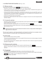
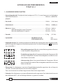
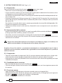
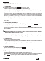
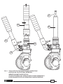
– Operating positions. The three operating positions are identified on the main handle, which
rotates relative to the reference symbol, (see Fig. 1).
Rest position (Handles locked): lock handles togethe when tool is
not in use.
Release position: close the moveable handle (56) against the main
handle (04), in order to discharge the oil pressure and retract the
dies.
Operating position: operate the moveable handle (56), to build up
pressure and close the dies.
– Advancing speed. The tool has a twin speed operation and automatically switches from a rapid
advancing speed of the ram to a slower, more powerful crimping speed.
– Safety. The tool is provided with a max pressure valve; MPC1 special manometer, is available as
an optional accessory to check the proper setting of the valve.
ENGLISH
LOCK

4
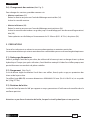
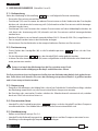
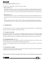
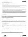
2. INSTRUCTIONS FOR USE (Ref. to Fig. 1 and 2)
2.1) Setting
With the tool is in rest position operate as follows:
– Select the appropriate die set for the connector.
– Insert the die (91) in the upper seat of the tool head until it is locked by die/head pin (34). To ease
the die insertion, keep die/head release pin (32) depressed.
– Insert the die (90) in the seat on the head of main ram (28) until it is locked by die/ram retainer
pin (39). To facilitate this operation an advancement of 15÷20 mm (0.59-0.79 in.) of the ram (28)
is suggested, then keep die/ram release pin (38) depressed.
– Insert the conductor in the connector.
– Position the connector between the dies and ensure the correct location of the crimp.
2.2) Die advancement
– Set the tool on release position by rotating main hanle (04); open the moveable handle
(56).
– Rotate main handle (04) to operating position .
– Operate moveable handle (56) for lower die advancement. This first stage rapidly closes the dies
to the connector.
Never place the tool under pressure without inserting the dies, as this could cause damage
to the head and the ram.
Make sure the dies are exactly positioned on desired crimp point, otherwise re-open dies following
instructions as per § 2.4 and position the connector again.
2.3) Crimping
– Continue operating the moveable handle (56). The tool will automatically change over to the
high pressure stage. The ram will advance until the dies meet.
– It is recommended to continue pumping until the maximum pressure valve is activated and a
"click" is heard.
2.4) Dies re-opening
– Rotate the main handle to release position .
Close handles thoroughly: the ram will then retract, with the consequent opening of the dies.
2.5) Rest setting
– Retract thoroughly the ram, operating as per § 2.4.
– Keeping handles closed rotate further the main handle to rest position ; the moveable
handle will be thus locked.
– Store the tool in the case.
ENGLISH
LOCK
LOCK

5
2.6) Die replacement (Ref. to Fig. 2)
To replace dies operate as follows:
– Upper die (91)
Take the die off its guide by pushing the die/head release pin (32).
Insert replacement die until secured by the die retaining pin (34).
– Lower die (90)
Take the die off its guide by pushing the die/ram release pin (38).
To facilitate this operation an advancement of 15÷20 mm (0.59-0.79 in.) of the ram (28) is sug-
gested.
Insert the new die in its guide till die/ram retainer pin (39) will hold it properly.
3. WARNING
The tool is robust and requires very little daily maintenance.
Compliance with the following points, should help to maintain the optimum performance of the tool.
3.1) Accurate cleaning
Dust, sand and dirt are a danger for any hydraulic device.
Every day, after use, the tool must be wiped with a clean cloth, taking care to remove any residue,
especially close to pivots and moveable parts.
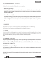
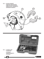
3.2) Storage (Ref. to Fig. 3)
When not in use, the tool should be stored and transported in the plastic case, to prevent damage.
These plastic case (Type VAL-P3) is dimensioned 620x380xh135 mm (24.4x14.9x5.3 in.) and weights
2,5 kg (5.5 lbs).
3.3) Head rotation
For ease of operation, the tool head can rotate through 180°.
Warning: do not attempt to turn the head if the hydraulic circuit is pressurised.
ENGLISH

6
4. MAINTENANCE (Ref. to Fig. 4 and 5)
Air in the hydraulic circuit may affect the performance of the tool; e.g. no lower die advancement,
slow advancement of the lower die; lower die pulsating.
In this case proceed as follows:
4.1) To purge air bubbles from hydraulic circuit
a – Hold tool upright in a vice with handles open (Fig. 4).
b – By an hexagonal 2,5 mm key, remove screw (65) and main handle (04) to expose oil reservoir
(03).
c – Remove reservoir cap (01).
d – Operate three or four times the moveable handle (56), to advance the ram (28).
e – Depress pressure release pin (73) until ram is fully retracted.
f – Repeat points (d - e) at least five times, to ensure all air bubbles in the hydraulic circuit are purged
into the reservoir.
g – If the oil level is low, top up as directed in § 4.2.
h – Remove all air from reservoir and fit cap (01).
i – Assemble main handle (04), and holding screw (65).
If the tool continues to malfunction return the tool for service/repair as detailed in § 6.
4.2) Oil top up
Every six months check the oil level in the reservoir. If necessary, top up the oil level to the upper lip
of the reservoir and remove all air from the reservoir, see 4.1, points a, b, c, e, g, h and i.
Always use clean recommended oil, see § 1.
Do not use old or recycled oil.
Do not use hydraulic brake fluid.
Ensure that disposal of used oil is in accordance with current legislation.
ENGLISH

7
ENGLISH
6800040 01 RESERVOIR CAP 1
6380265 02 MAIN HANDLE GRIP 1
6720100 03 OIL RESERVOIR 1
6480043 04 MAIN HANDLE 1
6760014 05 3x4 PIN 1
6780105 06 MAIN HANDLE SUPPORT 1
6360260 07 O-RING 1
6040685 08 GUIDING RING 2
6900621 09 SUCTION SCREW 1
6360160 10 O-RING 1
6740060 11 3/16" BALL 1
6520765 12 SUCTION SPRING 1
6160234 13 BODY 1
6740060 14 3/16" BALL 1
6520765 15 SUCTION SPRING 1
6740140 16 9/32" BALL 1
6520180 17 SPRING 1
6340566 18
BALL POSITIONING DOWEL
1
6900059 19 4x8 SCREW 1
6100020 20 KEY 1
6700250 21 SPRING RING 1
6170140 22 SPRING COVER 1
6362107 23 SEAL 1
6520620 25
RAM RETURN OUTER SPRING
1
6520610 26
RAM RETURN INNER SPRING
1
6300040 27 RAM SPRING GUIDE 1
6620315 28 RAM 1
6900211 29 5x10 SCREW 1
6100035 30 KEY 1
6370212 31 "C" HEAD 1
6620460 32 DIE HEAD RELEASE PIN 1
6760160 33 3x28 SPLIT PIN 1
6620440 34 DIE HEAD RETAINER PIN 1
6522006 35 SPRING 1
6340540 36 10x8 GRUB SCREW 1
6760040 37 3x8 SPLIT PIN 1
6620445 38 DIE RAM RELEASE PIN 1
6620320 39 DIE RAM RETAINER PIN 1
6522006 40 SPRING 1
6362035 41 SEAL 1
6362010 42 SEAL 1
6641140 43 BACK-UP RING 1
6360240 44 O-RING 1
6362020 45 SEAL 1
6620382 46 PUMPING RAM 1
6760320 47 5x30 SPLIT PIN 1
6780265 48
MOVEABLE HANDLE SUPPORT
1
6700100 49 SPRING RING 4
6080060 51
MOVEABLE HANDLE BUSHING
4
6560420 53 MOVEABLE HANDLE PIVOT 2
6200030 54
MOVEABLE HANDLE LATCH
1
6760280 55 4x30 SPLIT PIN 1
6480269 56 MOVEABLE HANDLE 1
6380240 57 MOVEABLE HANDLE GRIP 1
6232006 58 LABEL 1
6650118 59 RIVET 2
6232062 60 METAL LABEL (TG. 0262) 1
6760040 61 3x8 SPLIT PIN 1
6740020 62 1/4" BALL 1
6520280 63 MAIN HANDLE SPRING 1
6640205 64 WASHER 1
6900060 65 4x8 SCREW 1
6895050 66 MAX PRESSURE VALVE 1
6360160 67 O-RING 1
6740120 68 7/32" BALL 1
6600100 69
BALL POSITIONING DOWEL
1
6520260 70 SPRING 1
6740080 71 5/16" BALL 1
6340540 72 10x8 GRUB SCREW 1
6620120 73 PRESSURE RELEASE PIN 1
6360120 74 O-RING 1
6040060 75 BACK-UP RING 1
6080080 76
PRESSURE RELEASE RAM BUSHING
1
6900280 77 5x18 SCREW 1
6180200 78 M5 NUT 1
6340566 79
BALL POSITIONING DOWEL
1
6520180 80 NO RETURN SPRING 1
6740140 81 9/32" BALL 1
6635011 82 PRESSURE RELEASE PIN 1
6520861 83 PRESSURE RELEASE SPRING 1
6340720 84
PRESSURE RELEASE DOWEL
1
6480042 COMPLETE MAIN HANDLE
6620316 COMPLETE RAM
6370213 COMPLETE “C” HEAD
6480194
COMPLETE MOVEABLE HANDLE
6000074 SPARE PARTS PACKAGE
Code N°
INGLESE
DESCRIPTION QtyItem Code N° DESCRIPTION QtyItem
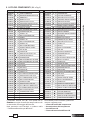
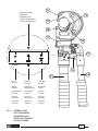
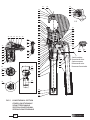
5. PARTS LIST (Ref. to Fig. 5)
The guarantee is void if parts used are not Cembre original spares.
When ordering spare parts always specify the
following:
- code number of item
- name of item
- type of tool
- tool serial number
The items marked () are those Cembre recom-
mend replacing if the tool is disassembled. These
items are included on request in the
“HT131-C Spare Parts Package”

8
PRESSE HYDRAULIQUE
TYPE HT131-C
1. CARACTERISTIQUES GENERALES
– Domaine d'application: conçue pour le sertissage des connecteurs électriques pour câbles
jusqu'à .................................................................................................................................. 400 mm
2
(800 MCM)
– Force de sertissage: ........................................................................................................ 130 kN (14.6 sh ton)
– Pression nominale: ......................................................................................................... 700 bar (10,000 psi)
– Dimensions: hauteur ...................................................................................................... 473 mm (18.6 in.)
largeur (bras mobile fermé) ............................................................... 144 mm (5.7 in.)
largeur (bras mobile ouvert) .............................................................. 344 mm (13.5 in.)
– Poids (sans matrices): ..................................................................................................... 5,5 kg (12.1 lbs)
– Huile: ..................................................................................ENI ARNICA ISO 22 ou
ESSO INVAROL EP22 ou équivalent
– Positions de fonctionnement: les trois positions de fonctionnement de la presse sont mention-
nées sur le bras principal (04), qui pivote sous le corps de presse, et sont sélectionnées face au
repère fixe (voir Fig. 1).
Repère de repos: c'est la position où l'outil doit être au repos.
Le bras mobile (56) est bloqué.
Repère de décompression: l'outil à cette position, en amenant et
maintenant le bras mobile (56) contre le bras principal (04) relache
sa pression et ouvre ainsi les matrices.
Repère de travail: l'outil à cette position, en actionnant le bras mobile
(56), permet la montée en pression et la fermeture des matrices.
– Avance rapide: l'outil passe automatiquement de la vitesse rapide d'approche des matrices, à la
vitesse lente de montée en pression.
– Sécurité: l'outil est pourvu d'une valve de surpression.
Pour vérifier le bon fonctionnement de cette valve, un manomètre spécial, notre réf. MPC1, est
disponible à la demande.
FRANÇAIS
LOCK

9
2. INSTRUCTIONS D'UTILISATION (Voir Fig. 1 et 2)
2.1) Mise en service
Avec l'outil en position de repos procéder comme suit:
– Prendre les matrices à utiliser selon le type de sertissage à effectuer.
– Insérer la partie (91) de la matrice dans son guide supérieur dans la tete de l'outil jusqu'à son
verrouillage par l'axe de verrouillage matrice/tete (34).
– Insérer la partie (90) de la matrice dans sa guide dans la tête du piston principal (28) jusqu'à son
verrouillage par l'axe de verrouillage matrice/piston (39). Cette opération est facilitée par l’avan-
cement de 15-20 mm (0.59 - 0.79 in.) du piston (28).
– Insérer le conducteur dans le connecteur.
– Positionner ce dernier entre les deux matrices en alignant la zone à sertir avec l'empreinte des
matrices mêmes.
2.2) Avance des matrices
– Empoigner l'outil et pivoter le bras principal (04) jusqu'à la position de décompression ;
le bras mobile (56) sera liberé.
– Pivoter ensuite le bras principal (04) jusqu'à la position de travail .
– En actionnant le bras mobile (56) le piston (28) amène rapidement les deux matrices au contact
du connecteur à sertir.
Ne jamais mettre l'outil sous pression sans les matrices inseres, cela pourrait endommager les
sieges de la tete et du piston.
S'assurer que les matrices sont bien positionnées sur la zone à sertir. Dans le cas contraire, les des-
serrer en suivant les instructions du § 2.4 et repositionner le connecteur.
2.3) Sertissage
– Poursuivre la manæuvre du bras mobile.
On passera automatiquement de la vitesse rapide à la lente; le piston montera progressivement
jusqu'au contact des matrices.
– Il est conseillé de continuer à pomper jusqu'à l'intervention de la valve de surpression (on doit
entendre un léger "clic").
2.4) Réouverture des matrices
– Faire pivoter le bras principal (04) dans la position de décompression .
Refermer à fond le bras mobile, on aura le retour du piston, et par conséquent l'ouverture des
matrices.
2.5) Rangement
– Faire descendre complétement le piston en suivant les indications du § 2.4.
– En maintenant fermé à fond les bras, pivoter ensuite le bras principal jusqu'à la position de repos
; le bras mobile sera ainsi bloqué par le loquet (54).
– Ranger l'outil dans son coffret.
FRANÇAIS
LOCK
LOCK

10
2.6) Changement des matrices(Voir Fig. 2)
Pour changer les matrices, procéder comme suit:
– Matrice supérieure (91)
Retirer la matrice en poussant l'axé de déblocage matrice/tête (34).
Insérer la nouvelle matrice.
– Matrice inférieure (90)
Retirer la matrice en poussant l'axe de déblocage matrice/piston (38).
Insérer la nouvelle matrice dans ses guides jusqu'à son blocage par l'axe de verrouillage matrice/
tête (39).
Cette opération est facilitée par l'avancement de 15-20 mm (0.59 - 0.79 in.) du piston (28).
3. PRECAUTIONS
Cet outil est robuste et ne nécessite aucune préoccupation ou entretien particulier.
Les recommandations qui suivent sont néanmoins souhaitables pour assurer une longévité optimum:
3.1) Nettoyage élémentaire
Veiller à protéger l'outil de la poussière, du sable et de la boue qui sont un danger à tout système
hydraulique. Chaque jour après utilisation, l'outil doit être nettoyé à l'aide d'un chiffon propre, tout
particulièrement aux endroits de pièces mobiles.
3.2) Rangement (Voir Fig. 3)
Il est de bonne règle de remettre l'outil dans son coffret, fermé, après usage, en protection des
chocs et de la poussière.
Ce coffret (type VAL-P3) a comme dimensions 620x380xh135 mm (24.4x14.9x5.3 in.) et un poids
de 2,5 kg (5.5 lbs).
3.3) Rotation de la tête
La tête de l'outil pivote de 180° par rapport au corps, permettant à l'utilisateur de travailler dans la
meilleure position.
Attention: ne pas forcer la rotation de la tête, lorsque le circuit hydraulique est sous pression.
FRANÇAIS

11
4. ENTRETIEN (Voir Fig. 4 et 5)
Le seul problème pouvant être rencontré parfois, nécessitant une intervention, est la présence d'une
bulle d'air dans le circuit hydraulique.
Cet incident est caractérisé par un mauvais fonctionnement de l'outil: dans l'action de montée en
pression, soit la matrice inférieure ne monte pas, soit elle progresse trés lentement, soit elle monte
et redescent pulsativement.
Dans ce cas, il est nécessaire de procéder comme suit:
4.1) Elimination de bulles d'air
a – Mettre l'outil en position verticale dans un étau (Fig. 4) en écartant le bras mobile (56).
b – A l'aide d'une clé 6 pans de 2,5 mm, ôter la vis (65) et degager complètement le bras principal
(04) laissant apparaître le réservoir d'huile en caoutchouc (03).
c – Retirer le capuchon (01) du réservoir.
d – Actionner 3 ou 4 fois le bras mobile (56), faisant avancer le piston principal (28).
e – Relâcher la pression d'huile, en compressant l'axe (73) jusqu'à la rétraction totale du piston et
de l'huile dans son réservoir.
f – Refaire les opérations (d - e) au moins 5 fois, afin de permettre aux éventuelles bulles d'air con-
tenues dans le circuit hydraulique d'être rejetées et évacuées par le réservoir d'huile.
g – Avant de refermer le réservoir d'huile, l'air doit être complètement évacué. Si le niveau d'huile
est bas, un complément doit être fait comme mentionné au § 4.2.
h – Refermer le capuchon.
i – Remonter le bras principal (04) et la vis (65) de blocage.
Dans l'éventuel cas où, malgré cette intervention, l'outil ne fonctionnerait pas correctement, (soit
la matrice inférieure ne monte pas, soit elle monte et rédescent pulsativement) il est recommandé
de le retourner à Cembre pour une révision complète (voir § 6).
4.2) Complément d'huile
La présence de bulles d'air est évitée en maintenant le réservoir d'huile toujours plein.
Par conséquent nous préconisons de vérifier tous les 6 mois, que le réservoir soit plein, et dans la
négative, de le compléter. Pour ce faire, reportez vous aux descriptions ci dessus: a, b, c, d et e, puis
emplir complètement le réservoir.
Après cela, terminer les opérations h et i.
Utiliser exclusivement un type d'huile mentionné au § 1.
Ne jamais utiliser d'huile usagée ou recyclée.
Il est indispensable que l'huile soit neuve.
En cas de changement d' huile, l'huile usagée doit être éliminée conformément aux normes
en vigueur.
FRANÇAIS

12
FRANÇAIS
N° Code
FRANCESE
Pièce
DENOMINATION Q.té N° Code
Pièce
DENOMINATION Q.té
6800040 01 CAPUCHON DE RESERVOIR 1
6380265 02 POIGNEE BRAS MOBILE 1
6720100 03 RESERVOIR 1
6480043 04 BRAS PRINCIPAL 1
6760014 05 GOUPILLE 3x4 1
6780105 06 EMBASE BRAS PRINCIPAL 1
6360260 07 JOINT TORIQUE 1
6040685 08 ANNEAU GUIDE 2
6900621 09 VIS ASPIRATION 1
6360160 10 JOINT TORIQUE OR 1
6740060 11 BILLE 3/16" 1
6520765 12 RESSORT ASPIRATION 1
6160234 13 CORPS 1
6740060 14 BILLE 3/16" 1
6520765 15 RESSORT ASPIRATION 1
6740140 16 BILLE 9/32" 1
6520180 17 RESSORT ANTI-RETOUR 1
6340566 18 GOUPILLE BILLE 1
6900059 19 VIS M 4x8 1
6100020 20 CLAVETTE 1
6700250 21 ANNEAU PLASTIQUE 1
6170140 22 COUVERCLE RESSORT 1
6362107 23 JOINT 1
6520620 25
RESSORT EXTER. RAPPEL PISTON
1
6520610 26
RESSORT INTER. RAPPEL PISTON
1
6300040 27 COUSSINET 1
6620315 28 PISTON 1
6900211 29 VIS 5x10 1
6100035 30 CLAVETTE 1
6370212 31 CHAPE EN"C" 1
6620460 32
AXE DE DEBLOQUAGE MATR./TETE
1
6760160 33 GOUPILLE 3x28 1
6620440 34
AXE DE VERROUILLAGE MATR./TETE
1
6522006 35 RESSORT 1
6340540 36 AXE M 10x8 1
6760040 37 GOUPILLE 3x8 1
6620445 38
AXE DE DEBLOQ. MATR./PISTON
1
6620320 39
AXE DE VERROUILL. MATR./PISTON
1
6522006 40 RESSORT 1
6362035 41 JOINT 1
6362010 42 JOINT R 6 1
6641140 43 ANNEAU BK 1
6360240 44 JOINT TORIQUE OR 1
6362020 45 JOINT TORIQUE JF 1
6620382 46 PISTON DE POMPAGE 1
6760320
47 GOUPILLE 5x30 1
6780265 48 EMBASE BRAS MOBILE 1
6700100 49 ANNEAU ELASTIQUE D 7 4
6080060 51 ANNEAU BRAS MOBILE 4
6560420 53 AXE BRAS MOBILE 2
6200030 54 LOQUET BRAS MOBILE 1
6760280 55 GOUPILLE D 4x30 1
6480269 56 BRAS MOBILE 1
6380240 57 POIGNEE BRAS MOBILE 1
6232006 58 ETIQUETTE 1
6650118 59 RIVET D 2.5x3.5 2
6232062 60 PLAQUETTE (TG. 0262) 1
6760040 61 BILLE 1/4" 1
6740020 62 BILLE 1/4" 1
6520280 63 RESSORT 1
6640205 64 RONDELLE 1
6900060 65 VIS 4x8 1
6895050 66 VALVE COMPLETE 1
6360160 67 JOINT OR 1
6740120 68 BILLE 7/32" 1
6600100 69 CLIQUET PORTE BILLE 1
6520260 70 RESSORT 1
6740080 71 BILLE 5/16" 1
6340540 72 GOUPILLE M 10x8 1
6620120 73 AXE DE DECOMPRESSION 1
6360120 74 JOINT OR 1
6040060 75 ANNEAU BK 1
6080080 76
ANNEAU AXE DE RETOUR PRESSION
1
6900280 77 VIS 5x18 1
6180200 78 ECROU M5 1
6340566 79 GOUPILLE BILLE 1
6520180 80 RESSORT ANTI-RETOUR 1
6740140 81 BILLE 9/32" 1
6635011 82 SOMMET DECOMPRESSION 1
6520861 83 RESSORT DE DECOMPRESS. 1
6340720 84
GOUPILLE DE DECOMPRESS.
1
6480042 BRAS PRINC.COMPLET
6620316 PISTON COMPLET
6370213 CHAPE EN "C" COMPLETE
6480194 BRAS MOBILE COMPLET
6000074 PAQUET RECHANGE
5. PIECES DETACHEES (Voir Fig. 5)
La garantie perd tout effet en cas d'emploi de pièces détachées différentes des pièces d'origine Cembre.
Les éléments accompagnés d'un () sont ceux que
Cembre recommande de remplacer en cas de démon-
tage de l'outil.
Ces éléments sont fournis sur demande dans le “Paquet
Rechange pour HT131-C”.
Lors de la commande de pièces détachées, veuillez indiquer
toujours les éléments suivants:
- numéro de code article de la pièce
- désignation de la pièce
- type d'outil
- numéro de série de l'outil

13
HYDRAULISCHES PRESSWERKZEUG
TYPHT131-C
1. ALLGEMEINE EIGENSCHAFTEN
– Anwendungsbereich: Die hydraulische Handpresse HT131-C ist zum Verpressen von Verbindern
und Kabelschuhen bis ................................................................................................... 400 mm
2
(800 MCM)
geegnet.
– Presskraft: ........................................................................................................................... 130 kN (14.6 sh ton)
– Arbeitsdruck: ..................................................................................................................... 700 bar (10,000 psi)
– Abmasse: Länge .............................................................................................................. 473 mm (18.6 in.)
Breite bei geschlossenem Pumparm .................................................. 144 mm (5.7 in.)
Breite bei geöffnetem Pumparm .......................................................... 344 mm (13.5 in.)
– Gewicht: .............................................................................................................................. 5,5 kg (12.1 lbs)
– Hydrauliköl: ....................................................................ENI ARNICA ISO 22 oder
ESSO INVAROL EP22 oder ähnlich
– Arbeitspositionen: Die 3 Arbeitspositionen des Werkzeuges werden durch den drehbaren Hand-
griff (04) eingestellt. Die gewünschte Arbeitsoperation muss mit dem Piktogramm übereinstim
men (siehe Bild 1).
Ruhestellungsposition: Befindet sich das Werkzeug in dieser Position,
ist der Pumparm (56) geschlossen.
Druckablassposition: Beim Zusammendrücken des Pumparmes (56)
mit dem Handgriff (04) wird der Öldruck abgebaut und die Pressein-
sätze fahren auseinander.
Arbeitsposition: Beim Zusammendrücken des Pumparmes (56) mit
dem Handgriff (04) wird der Öldruck abgebaut und die Presseinsätze
fahren zusammen.
– Eilvorschub. Das Werkzeug ist mit einer Doppelkolbenhydraulik ausgerüstet, die an fangs ein
schnelles Zusammenfahren der Presseinsätze ermöglicht.
Dann wird automatisch auf den langsameren Arbeitshub umgeschaltet.
– Sicherheit. Das Werkzeug ist mit einem Überdruckventil ausgestattet. Der Arbeitsdruck kann mit
dem Meßgerät MPC1, das auf Anfrage lieferbar ist, gemessen werden.
DEUTSCH
LOCK

14
2. BEDIENUNGSHINWEISE (Siehe Bild 1 und 2)
2.1) Vorbereitung
Wenn das Werkzeug in Ruhestellung ist, sind folgende Schritte notwendig:
– Passenden Presseinsatz auswählen.
– Druckknopf (32) zum Einsetzen des oberen Presseinsatzes auf der Vorderseite des Presskopfes
drücken, da sich damit der Arretierungsstift (34) absenkt und der Presseinsatz seitlich heirenge-
schoben werden kann.
– Druckknopf (38) zum Einsetzen des unteren Presseinsatzes auf dem Kolbenkopfe drücken, da
sich damit der Arretierungsstift (39) absenkt und der Presseinsatz seitlich heirengeschoben
werden kann.
– Bei dieser Tätigkeit ist es von Vorteil, wenn der Kolben (28) 15–20 mm (0.59-0.79 in.) vorgefahren ist.
– Den zu verpressenden Leiter in den Verbinder einlegen.
– Positionieren Sie den Verbinder an der vorgeschriebenen Position am Presseinsatz.
2.2) Positionierung
– Durch Drehen des Handgriffes (04) in die Druckablassposition öffnet sich der Pum-
parm (56).
– Für die Arbeitsposition muss der Handgriff (04) weiter gedreht werden.
– In dieser Position kann der Kolben (28) etwas vorgefahren und der Verbinder oder Kabelschuh
exakt positioniert werden.
Setzen sie niemals das Werkzeug ohne die Presseinsätze unter Druck.
Die könnte zu Beschädigungen des Kopf- und Kolbensitzes führen.
Die Presseinsätze müssen in die gewünschte Position am Verbinder oder Kabelschuh gebracht wer-
den. Sollte diese nicht korrekt sein, muss das Werkzeug entsprechend Punkt 2.4, geöffnet werden
und es kann neu positioniert werden.
2.3) Verpressung
– Pumparm (56) betätigen, der Kolben fährt schnell vor. Sobald der Druckaufbau erfolgt, schaltet
das Werkzeug automatisch um, die Presseinsätze fahren langsam zusammen.
– Bei Erreichen des maximalen Druckes schaltet das Überdruckventil automatisch ab, welches
durch ein "Klick" akustisch zu hören ist.
2.4) Presseinsätze lösen
– Handgriff in die Druckablassposition drehen und den Handgriff und den Pumparm
zusammendrücken. Der Kolben fährt zurück und die Presseinsätze öffnen sich.
2.5) Nachbereitung
– Kolben zurückfahren entspr. Pkt. 2.4.
– Handgriff in die Ruhestellungsposition drehen und den Pumparm einrasten lassen.
– Werkzeug in die dazugehörige Verpackungseinheit legen.
DEUTSCH
LOCK
LOCK

15
2.6) Presseinsatzwechsel (Siehe Bild 2)
Für den Presseinsatz wechsel folgender masse vorgehen:
– Oberer Presseinsatz (91)
Druckknopf (32) zum Einsetzen des oberen Presseinsatzes auf der Vorderseite des Presskopfes
drücken, da sich damit der Arretierungsstift (34) anhebt und der Presseinsatz seitlich herausge-
schoben werden kann.
– Unterer Presseinsatz (90)
Druckknopf (38) zum Einsetzen des unteren Presseinsatzes auf dem Kolben drücken, da sich damit
der Arretierungsstift (39) anhebt und der Presseinsatz seitlich herasgeschoben werden kann.
Bei dieser Tätigkeit ist es von Vorteil, wenn der Kolben (28) 15-20 mm (0.59 - 0.79 in.) vorgefahren
ist.
3. HINWEISE
Das Werkzeug ist robust und benötigt keine spezielle Pflege oder Instandhaltung.
Zur Erhaltung der Garantieansprüche beachten Sie folgende Hinweise:
3.1) Pflege
Dieses hydraulische Werkzeug sollte vor starker Verschmutzung geschützt werden, da diese für ein
hydraulisches System gefährlich ist. Jeden Tag nach der Arbeit sollte das Werkzeug mit einem Tuch
von Schmutz und Staub gereinigt werden, besonders die beweglichen
Teile.
3.2) Lagerung (Siehe Bild 3)
Wenn das Werkzeug nicht benötigt wird, sollte es in der abschliessbaren Kunststoffkassette gelagert
werden und ist somit gegen Beschädigungen wie Stoss und Staub geschützt.
Die Kunststoffkassette (Typ VAL-P3) hat die Abmasse 620x380xh135 mm (24.4x14.9x5.3 in.) und
ein Gewicht von 2,5 kg (5.5 lbs).
3.3) Drehbewegung des Kopfes
Das Werkzeug ist mit einem Kopf ausgerüstet, der um 180° drehbar ist und somit ein komfortables
Arbeiten ermöglicht.
Der Kopf sollte keinesfalls in eine andere Position gedreht werden, während die Handpresse unter
Druck steht.
DEUTSCH

16
4. WARTUNG (Siehe Bild 4 und 5)
Befindet sich Luft im Hydrauliksystem, kann es zum fehlerhaften Arbeiten des Werkzeuges kommen.
Dieser zeigt sich in ungewöhnlichem Verhalten des Werkzeuges: bei Pumpbeginn bewegen sich
die unteren Presseinsätze nicht oder nur sehr langsam bzw. stossweise.
Ist dies der Fall, sind die folgenden Hinweise zu beachten:
4.1) Entlüften
a – Werkzeug mit dem Presskopf nach unten (Bild 4) positionieren.
Dabei muss der Pumparm in der Öffnungsstellung sein.
b – Imbusschraube 2.5 (65) lösen und Handgriff (04) vom Öltank (03) ziehen.
c – Ölverschlusskappe (01) entfernen.
d – Mit dem Pumparm (56) den Kolben (73) ca. 5 mm vorfahren.
e – Öldruck wieder ablassen und der Kolben fährt vollständig zurück.
f – Vorgang (d - e) einige Male wiederholen, so dass die gesamte Luft ausgetreten ist oder sich im
Öltank gesammelt hat.
g – Bevor der Öltank geschlossen wird, kann bei Bedarf noch Öl nachgefüllt werden siehe Pkt. 4.2.
h – Öltank verschliessen.
i – Handgriff über den Öltank schieben und Schraube (65) anziehen.
Sehr selten kann es passieren, dass das Werkzeug nach diesen Wartungsarbeiten nicht oder nicht
richtig funktioniert. In diesem Fall sollte entspr. Pkt. 6 verfahren werden.
4.2) Öl nachfüllen
Luftblasen im Öltank lassen sich vermeiden, wenn der Tank stets gut gefüllt ist.
Deshalb sollte alle 6 Monate der Tank kontrolliert und bei Bedarf aufgefüllt werden.
Dies erfolgt so wie in den Punkten a, b, c und e beschrieben wurde.
Danach wird der Öltank aufgefüllt.
Zuletzt wird wie in Punkt h und i beschrieben vorgegangen.
Zum Nachfüllen stets das unter Pkt.1 angegebene Öl verwenden.
Niemals mit gebrauchtem oder altem Öl nachfüllen.
Das Öl muss stets sauber sein.
Bei einem Ölwechsel sind unbedingt die vorgeschriebenen Normen zur Entsorgung von Altöl
zu beachten.
DEUTSCH

17
DEUTSCH
TEDESCO
Codenr.
Menge
BESCHREIBUNG
Teil
6800040 01 ÖLVERSCHLUSSKAPPE 1
6380265 02 GUMMIHANDGRIFF 1
6720100 03 ÖLTANK 1
6480043 04 HANDGRIFF 1
6760014 05 3x4 STIFT 1
6780105 06 HANGRIFFHALTERUNG 1
6360260 07 O-RING 1
6040685 08 FÜHRUNGSRING 2
6900621 09 ANSAUGSCHRAUBE 1
6360160 10 O-RING 1
6740060 11 3/16" KUGEL 1
6520765 12 ANSAUGFEDER 1
6160234 13 GRUNDKÖRPER 1
6740060 14 3/16" KUGEL 1
6520765 15 ANSAUGFEDER 1
6740140 16 9/32" KUGEL 1
6520180 17 FEDER 1
6340566 18
KUGEL POSITIONIERUNGSSCHRAUBE
1
6900059 19 4x8 SCHRAUBE 1
6100020 20 ABDECKUNG 1
6700250 21 FEDERRING 1
6170140 22 FEDERDECKEL 1
6362107 23 DICHTUNG 1
6520620 25
AUSSERE KOLBENRÜCKHOLFEDER
1
6520610 26
INNERE KOLBENRÜCKHOLFEDER
1
6300040 27 KOLBENFÜHRUNG 1
6620315 28 KOLBEN 1
6900211 29 5x10 SCHRAUBE 1
6100035 30 STÜTZPLÄTCHEN 1
6370212 31 C-KOPF 1
6620460 32 DRUCKKNOPF 1
6760160 33 3x28 STIFT 1
6620440 34 ARRETIERUNGSTIFT 1
6522006 35 FEDER 1
6340540 36 10x8 STIFT 1
6760040 37 3x8 FEDERSTIFT 1
6620445 38 DRUCKKNOPF 1
6620320 39 ARRETIERUNGSTIFT 1
6522006 40 FEDER 1
6362035 41 ABSTREIFRING 1
6362010 42 STÜTZRING 1
6641140 43 STÜTZRING 1
6360240 44 O-RING 1
Codenr.
Menge
BESCHREIBUNG
Teil
6362020 45 STÜTZRING 1
6620382 46 PUMPKOLBEN 1
6760320 47 5x3 STIFT 1
6780265 48 PUMPARMHALTERUNG 1
6700100 49 SPRENGRING 4
6080060 51 PUMPARMBUCHSE 4
6560420 53 PUMPARMBOLZEN 2
6200030 54
PUMPARMARRETIERUNGSSTIFT
1
6760280 55 5x30 STIFT 1
6480269 56 PUMPARM 1
6380240 57 GUMMIGRIFF 1
6232006 58 AUFKLEBER 1
6650118 59 NIET 2
6232062 60 TYPENSCHILD (TG. 0262) 1
6760040 61 3x8 STIFT 1
6740020 62 1/4" KUGEL 1
6520280 63 HANDGRIFFEDER 1
6640205 64 SCHEIBE 1
6900060 65 4x8 SCHRAUBE 1
6895050 66 ÜBERDRUCKVENTIL 1
6360160 67 O-RING 1
6740120 68 7/32" KUGEL 1
6600100 69 KUGELHALTER 1
6520260 70 FEDER 1
6740080 71 5/16" KUGEL 1
6340540 72 10x8 STIFT 1
6620120 73 DRUCKABLASSKOLBEN 1
6360120 74 0-RING 1
6040060 75 ABSREIFRING 1
6080080 76 BUCHSE 1
6900280 77 5x18 SCHRAUBE 1
6180200 78 MUTTER M 5 1
6340566 79 KUGELHALTER 1
6520180 80 GEGENDRUCKFEDER 1
6740140 81 9/32" KUGEL 1
6635011 82 DRUCKABLASSTIFT 1
6520861 83 DRUCKABLASSFEDER 1
6340720 84 DRUCKABLASSPASSTIFT 1
6480042 VORMONTIERTE HANDGRIFF
6620316 VORMONTIERTE KOLBEN
6370213 VORMONTIERTE C-KOPF
6480194 VORMONTIERTE PUMPARM
6000074 ERSATZTEILPACKUNG
5. ERSATZTEILLISTE (Siehe Bild 5)
Die Garantie verfällt, wenn nicht Originalteile aus dem Hause Cembre in das Gerät eingebaut werden.
Geben Sie bitte bei der Bestellung aller Ersatzteile
folgende Informationen an:
- Codenummer des Ersatzteils
- Beschreibung des Ersatzteils
- Werkzeug Typ
- Seriennr. des Werkzeugs
Die mit () gekennzeichneten Bestandteile sind
jene, welche Cembre auszuwechseln empfiehlt,
falls das Gerät in seine Bestandteile zerlegt wird.
Genannte Einzelteile sind auf Anfrage in der “Er-
satzteilpackung HT131-C" erhältlich.

18
HERRAMIENTA HIDRAULICA DE COMPRESION
TIPO HT131-C
1. CARACTERISTICAS GENERALES
– Campo de aplicación: idónea para la instalación de conectores eléctricos, por compresión, para
conductores en general hasta ................................................................................... 400 mm
2
(800 MCM)
– Fuerza desarrollada: ....................................................................................................... 130 kN (14.6 sh ton)
– Presión nominal de trabajo: ....................................................................................... 700 bar (10,000 psi)
– Dimensiones: longitud .................................................................................................. 473 mm (18.6 in.)
anchura (con mango móvil cerrado) ........................................... 144 mm (5.7 in.)
anchura (con mango móvil liberado) .......................................... 344 mm (13.5 in.)
– Peso (sin matrices): .......................................................................................................... 5,5 kg (12.1 lbs)
– Aceites recomendados: .............................................ENI ARNICA ISO 22 o bien
ESSO INVAROL EP22 o equivalentes
– Posiciones fundamentales: Son 3, definidas por los siguientes símbolos, abajo descritos y que
se obtienen girando el mango fijo (04), respecto al cuerpo (13), hasta alinear el símbolo de la
posición deseada con el símbolo de la referencia (ver Fig. 1).
Posición de reposo: es la posición en la cual debe permanecer la
herramienta cuando no se está tilizando.
El mango móvil (56) estará bloqueado.
Posición de liberación: con la herramienta en esta posición, cerrando
el mango móvil (56) contra el mango fijo (04) se obtiene la descarga
de la presión del aceite y por consiguiente la apertura de las matrices.
Posición de trabajo: con la herramienta en esta posición, accionando
el mango móvil (56), se comprime el aceite que hace avanzar el pistón
(28) y como consecuencia se cierran las matrices.
– Velocidad de avance. Son dos: una rápida de aproximación de las matrices y otra más lenta de
compresión. El paso de una a otra velocidad es automático.
– Seguridad. La herramienta esta provista de una válvula de seguridad con la que la compresión
correcta es verificable mediante el instrumento adecuado MPC1 disponible mediante pedido.
ESPAÑOL
LOCK

19
2. INSTRUCCIONES DE USO (Ref. Figg. 1 y 2)
2.1) Preparación
Con la herramienta en posición de reposo opere como sigue:
– Seleccione la matriz adecuada para la conexión a efectuar.
– Inserte una de las matrices (91) en el hueco-guía superior,de la cabeza de la herramienta, hasta
su bloqueo con el pistoncillo fija-matriz/cabeza (34).
Para facilitar la insercion de la matriz, mantenga presionado el pistoncillo desbloqueador de ma-
trices/cabeza (32).
– Accionar el mango móvil (56) para avanzar de 15-20 mm (0.59-0.79) el pistón (28) y inserte la otra
matriz (90) en la guía, localizada sobre la cabeza del pistón hasta su bloqueo con el pistoncillo
fija matriz (39).
Para facilitar la inserción de la matriz, mantenga presionado el pistoncillo desbloqueador (38).
– Introduca el conductor en el conector.
– Coloque este último entre las dos matrices, alineando la zona a comprimir con la marca de las
matrices.
2.2) Aproximación de las matrices
– Empuñe la herramienta y gire sobre si mismo el mango fijo (04) en posición de liberado ;
el mango móvil (56) se libera y puede se accionado.
– Gire sobre si mismo a continuación, el mango fijo en posición de trabajo .
– Accionando el mango móvil (56), el pistón (28) avanzará rápidamente, poniendo las matrices en
contacto con el conector.
No presione nunca la herramienta sin las matrices insertadas en su lugar, en la cabeza, esto
podría ocasionar daños a los alojamientos de la cabeza y del pistón.
Asegúrese de que las matrices se encuentran exactamente en correspondencia con la zona a
comprimir; en caso contrario, vuélvala a abrir, siguiendo las instrucciones del punto 2.4 y vuelva a
colocar el conector.
2.3) Compresión
– Continúe accionando el mango móvil (56). Se pasará automáticamente de la alta a la baja velo-
cidad; el pistón avanzará progresivamente hasta colocar las matrices sobre el conector.
– Aconsejamos, en todo caso, bombear hasta la intervención de la válvula de seguridad, por la que
se advertirá el disparo.
2.4) Desbloqueo de las matrices
– Rote el mango fijo hasta la posición de liberado .
– Cierre los mangos a fondo, se alcanzará así el retorno del pistón, con la consiguiente apertura de
las matrices.
2.5) Puesta en reposo
– Haga retroceder, completamente, el pistón actuando como en el epígrafe 2.4.
– Manteniendo cerrados a fondo los mangos,rote, a continuación, el mango fijo hasta la posición
de reposo ; el mango móvil quederá así bloqueado.
– Vuelva a colocar la herramienta en su estuche.
ESPAÑOL
LOCK
LOCK

20
2.6) Cambio de las matrices (Ref. Fig. 2)
Para efectuar el cambio de las matrices, actúe como sigue:
– Matriz superior (91)
Desencaje la matriz de sus guías, manteniendo presionado el pistoncillo desbloquea-matrices/
cabeza (32), con el fin de anular la acción de retención del pistoncillo fija matrices/cabeza (34).
Inserte la nueva matriz en sus guías, hasta el bloqueo con el pistoncillo fija-matrices/cabeza (34).
– Matriz inferior (90)
Desencaje la matriz de sus guías, manteniendo presionado el pistoncillo desbloqueador de ma-
trices/pistón (38), con el fin de anular la acción de retención del pistoncillo fija matrices/pistón
(39).
Es aconsejable avanzar de 15÷20 mm (0.59 - 0.79 in.) el pistón (28) para facilitar la operación.
Inserte la nueva matriz en sus guías, hasta su bloqueo con el pistoncillo fija matrices/pistón (39).
3. ADVERTENCIAS
Esta herramienta es robusta y no requiere cuidados especiales para obtener un funcionamiento
correcto, bastará tener algunas precauciones sencillas:
3.1) Limpieza adecuada
Tenga presente que el polvo, la arena y la suciedad en general, rapresentan un peligro para toda
herramienta hidráulica. Tras cada día de uso, se debe limpiar la herramienta con un trapo limpio,
teniendo cuidado de eliminar la suciedad depositada, especialmente junto a las partes móviles.
3.2) Almacenamiento (Ref. Fig. 3)
Para proteger la herramienta de golpes accidentales y del polvo cuando no se va a utilizar, es con-
veniente guardarla en su estuche de plástico de cierre hermético.
Dicho estuche (mod. VAL-P3) de dimensiones 620x380xh135 mm (24.4x14.9x5.3 in.) y pesa 2,5 kg
(5.5 lbs).
3.3) Rotación de la cabeza
La cabeza de la herramienta puede rotar hasta 180° respecto al cuerpo, permitiendo al operario
realizar el trabajo en la posición más adecuada.
Atención: no fuerce la cabeza, intentando rotarla, mientras el circuito hidráulico esté presurizado.
ESPAÑOL
A página está carregando ...
A página está carregando ...
A página está carregando ...
A página está carregando ...
A página está carregando ...
A página está carregando ...
A página está carregando ...
A página está carregando ...
A página está carregando ...
A página está carregando ...
A página está carregando ...
A página está carregando ...
-
 1
1
-
 2
2
-
 3
3
-
 4
4
-
 5
5
-
 6
6
-
 7
7
-
 8
8
-
 9
9
-
 10
10
-
 11
11
-
 12
12
-
 13
13
-
 14
14
-
 15
15
-
 16
16
-
 17
17
-
 18
18
-
 19
19
-
 20
20
-
 21
21
-
 22
22
-
 23
23
-
 24
24
-
 25
25
-
 26
26
-
 27
27
-
 28
28
-
 29
29
-
 30
30
-
 31
31
-
 32
32


em outros idiomas
- español: Cembre HT131-C Manual de usuario
- français: Cembre HT131-C Manuel utilisateur
- italiano: Cembre HT131-C Manuale utente
- Deutsch: Cembre HT131-C Benutzerhandbuch
Artigos relacionados
-
Cembre HT131LN-C Manual do usuário
-
-
-
-
-
-
-
-
-