SICK PowerProx - WTT12L MultiTask photoelectric sensor Instruções de operação
- Tipo
- Instruções de operação

O P E R A T I N G I N S T R U C T I O N S
PowerProx - WTT12L
MultiTask photoelectric sensor
en / de / fr / it / pt / es / zh / ja / ru


Described product
PowerProx - WTT12L
Manufacturer
SICK AG
Erwin-Sick-Str. 1
79183 Waldkirch
Germany
Legal information
This work is protected by copyright. Any rights derived from the copyright shall be
reserved for SICK AG. Reproduction of this document or parts of this document is
only permissible within the limits of the legal determination of Copyright Law. Any modi‐
fication, abridgment or translation of this document is prohibited without the express
written permission of SICK AG.
The trademarks stated in this document are the property of their respective owner.
© SICK AG. All rights reserved.
Original document
This document is an original document of SICK AG.
2
8018110.1BVZ / 2021-05-18 | SICK
Subject to change without notice

Contents
1 General safety notes......................................................................... 4
1.1 Safety notes.............................................................................................. 4
2 Product description........................................................................... 4
2.1 Correct use................................................................................................ 4
2.2 Dimensional drawings.............................................................................. 5
2.3 Additional functions.................................................................................. 5
3 Commissioning.................................................................................. 6
3.1 Check the application conditions:........................................................... 6
3.2 Mounting................................................................................................... 6
3.3 Electronics................................................................................................. 7
3.4 Alignment.................................................................................................. 8
4 Configuration..................................................................................... 8
4.1 Adjustment................................................................................................ 8
4.2 WT teach modes....................................................................................... 10
5 Troubleshooting................................................................................. 10
5.1 Troubleshooting........................................................................................ 10
6 Technical data.................................................................................... 11
7 Disassembly and disposal............................................................... 11
8 Maintenance...................................................................................... 12
CONTENTS
8018110.1BVZ / 2021-05-18 | SICK
Subject to change without notice
3

1 General safety notes
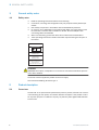
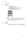
1.1 Safety notes
■
Read the operating instructions before commissioning.
■
Connection, mounting, and configuration may only be performed by trained spe‐
cialists.
■
Not a safety component in accordance with the EU Machinery Directive.
■
UL: Only for use in applications in accordance with NFPA 79. These devices must
be fused with a 1 A fuse that is suitable for 30 VDC. UL-listed adapters with
connecting cables are available.
■
When commissioning, protect the device from moisture and contamination.
■
These operating instructions contain information required during the life cycle of
the sensor.
EN/IEC 60825-1:2014
IEC60825-1:2007
Laser
1
Maximale Pulsleistung: < 250 mW
Impulsdauer: 4 ns
Wellenlänge: 658 nm
Entspricht 21 CFR 1040.10
und 1040.11 mit Ausnahme von
Abweichungen nach
Laser-Hinweis 50, 24. Juni 2007
LASERKLASSE 1
ATTENTION
WARNING: Interruption, manipulation or incorrect use can lead to hazardous exposure
due to laser radiation.
The device must be supplied by a Class 2 source of supply.
UL Environmental Rating: Enclosure type 1
2 Product description
2.1 Correct use
The WTT12L is an opto-electronic photoelectric proximity sensor (referred to as "sensor"
in the following) for the optical, non-contact detection of objects. If the product is used
for any other purpose or modified in any way, any warranty claim against SICK AG shall
become void.
1 GENERAL SAFETY NOTES
4
8018110.1BVZ / 2021-05-18 | SICK
Subject to change without notice

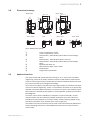
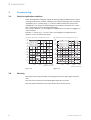
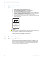
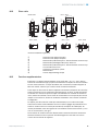
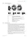
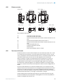
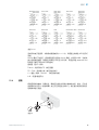
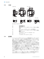
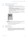
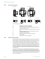
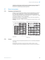
2.2 Dimensional drawings
WTT12L-X2xxx -X1xxx / -X3xxx
-Xxxx2 / -Xxxx4 -Xxxx1
-Xxxx3 / -Xxxx7 -Xxxx6 / -Xxxx8
1
2
7
6
7
9
8
3
4
5
20
(0.79)
44.2 (1.74)
31.9 (1.26)
6 (0.24)
44.2 (1.74)
31.9 (1.26)
6 (0.24)
Ø 4.2
(0.17)
Ø 4.2
(0.17)
49.6 (1.95)
5.1 (0.2)
48.7 (1.92)
61.6 (2.43)
47 (1.85)18.5 (0.73)
36.3 (1.43)
21.1
(0.83)
M12x1
36.5 (1.44)
4 (0.16)
5.1 (0.2)
48.7 (1.92)
4 (0.16)
36.5 (1.44)
6 (0.24)
8 (0.31)
18.3
(0.72)
18.3
(0.72)
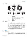
Figure: Maßzeichnung WTT12L
1
Center of optical axis, sender
2
Center of optical axis, receiver
3
Potentiometer / LED indicator yellow: status of received light
beam
4
Potentiometer / LED Indicators (green): Power on
5
Potentiometer / LED indicator yellow: status of received light
beam
6
Mounting hole D4.2 mm
7
Male connector, M12, 4-pin or cable
8
Potentiometer
9
Single teach-in pushbutton
2.3 Additional functions
Test input: The WTT12L sensor features a test input ("TI" or "Test" on the connection
diagram [B]), which can be used to switch the sender off and therefore check that the
sensor is functioning correctly: If female cable connectors with LED indicators are used,
you must ensure that the TI is assigned accordingly.
There must be an object in the path of the beam (light reception); activate the test input
(see the connection diagram [B], TI 24 V). The send LED is shut down or no object being
detected is simulated. Refer to Graphics C to check the function. If the switching output
fails to behave in accordance with Graphic C, check application conditions. See section
Fault diagnosis.
The sensor can be used in standard I/O mode (SIO) or IO-Link mode (IOL). All auto‐
mation functions and other parameter settings are effective in IO-Link mode and in
standard I/O mode (exception: time stamp). Output of binary switching signals during
standard I/O operation via pin 4/black wire or via pin 5/gray wire.
Information on the IO-Link functions can be found in the enclosed IO-Link photoelectric
sensors operating instructions or downloaded from www.sick.com under the device
order number.
PRODUCT DESCRIPTION 2
8018110.1BVZ / 2021-05-18 | SICK
Subject to change without notice
5

3 Commissioning
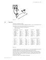
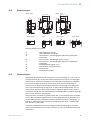
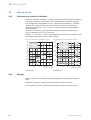
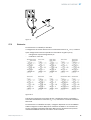
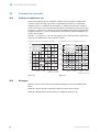
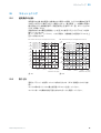
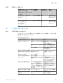
3.1 Check the application conditions:
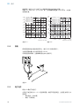
Check the application conditions: Adjust the sensing range and distance to the object
or background and the remission capability of the object according to the correspond‐
ing diagram [H] (x = sensing range, y = minimum distance between the object and
background in mm (object remission/background remission) (remission: 6% = black,
90% = white (based on standard white DIN 5033))).
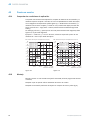
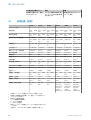
The minimum distance (= y) for background suppression can be read from diagram [H
15] as follows:
Example: x = 1,000 mm, y = 20 mm. That is, the background is suppressed at a
distance of > 20 mm behind the object.
0
5
(0.2)
10
(0.39)
15
(0.59)
20
(0.79)
25
(0.98)
30
(1.18)
35
(1.38)
40
(1.57)
0
1
6%/90%
2
6%/90%
90%/90%
5
4
90%/90%
3
6%/90%
6
90%/90%
Min. distance from object to background in mm (inch)
1,000
(39.37)
2,000
(78.74)
3,000
(118.11)
4,000
(157.48)
Distance in mm (inch)
1) -Bxx3x: 6 % / 90 %
2) -Bxx3x: 90 % / 90 %
3) -Bxx6x: 6 % / 90 %
4) -Bxx6x: 90 % / 90 %
5) -Bxx4x: 6 % / 90 %
6) -Bxx4x: 90 % / 90 %
Figure: H-1
0
4
5
6
90%/90%
90%/90%
90%/90%
1
6%/90%
2
3
6%/90%
6%/90%
30
(1.18)
20
(0.79)
10
(0.39)
50
(1.97)
40
(1.57)
500
(19.69)
1,000
(39.37)
1,500
(59.06)
2,000
(78.74)
Min. distance from object to background in mm (inch)
Distance in mm (inch)
1) -Bxx1x: 6 % / 90 %
2) -Bxx1x: 90 % / 90 %
3) -Bxx5x: 6 % / 90 %
4) -Bxx5x: 90 % / 90 %
5) -Bxx2x: 6 % / 90 %
6) -Bxx2x: 90 % / 90 %
Figure: H-2
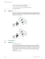
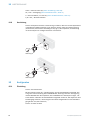
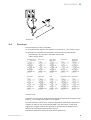
3.2 Mounting
Mount the sensor using a suitable mounting bracket (see the SICK range of accesso‐
ries).
Note the sensor's maximum permissible tightening torque of 0.8 Nm.
Note the preferred direction of the object relative to the sensor [see E].
3 COMMISSIONING
6
8018110.1BVZ / 2021-05-18 | SICK
Subject to change without notice

Figure: E
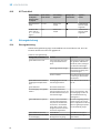
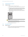
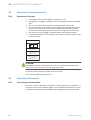
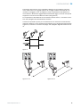
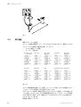
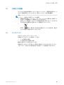
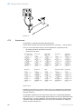
3.3 Electronics
Operation in standard I/O mode:
The sensors must be connected in a voltage-free state (U
v
= 0 V). The information in the
graphics [B] must be observed, depending on the connection type:
– Male connector connection: pin assignment
– Cable: core color
Figure 1: B
Only apply voltage/switch on the power supply (U
v
> 0 V) once all electrical connections
have been established. The green LED indicator lights up on the sensor.
Operation in IO-Link mode: Connect the device to a suitable IO-Link master and inte‐
grate in the master or control via IODD/function block. The green LED indicator flashes
on the sensor. IODD and function block are available to download from www.sick.com
under the order number.
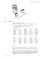
Explanations of the connection diagram (Graphic B):
COMMISSIONING
3
8018110.1BVZ / 2021-05-18 | SICK
Subject to change without notice
7

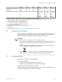
Teach-in = external teach-in (ET) (see Adjustment)
TI / Test = test input (see Additional functions)
C = communication (e.g., IO-Link) (see Additional functions)
L/D = light/dark switch
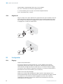
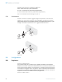
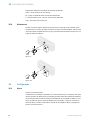
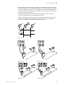
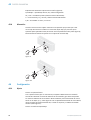
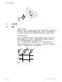
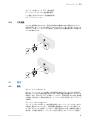
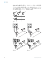
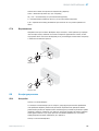
3.4 Alignment
Align the sensor with the object. Select the position so that the red emitted light beam
hits the center of the object. You must ensure that the optical opening (front screen)
of the sensor is completely clear [E]. We recommend making the adjustments using an
object with a low remission.
1.
2.
Figure: E
1.
2.
Figure: E-2
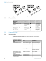
4 Configuration
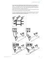
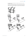
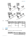
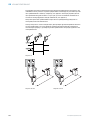
4.1 Adjustment
Sensor with potentiometer:
The sensing range is adjusted with the potentiometer (type: 4 rotations). Clockwise
rotation: sensing range increased; counterclockwise rotation: sensing range reduced.
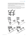
We recommend placing the switching state in the object, e. g., see graphic E. Once the
sensing range has been adjusted, the object is removed from the path of the beam,
which causes the background to be suppressed and the switching output to change
(see graphic C).
Sensor with teach-in button:
3 COMMISSIONING
8
8018110.1BVZ / 2021-05-18 | SICK
Subject to change without notice

The sensing range is adjusted by pressing the teach-in button. Do not operate the
teach-in button using sharp objects. We recommend placing the switching state in the
object, e. g., see graphic E. Once the sensing range has been adjusted, the object is
removed from the path of the beam, which causes the background to be suppressed
and the switching output to change (see graphic C).
Please refer to the enclosed operating instructions for the IO-Link photoelectric sensor
for information about adjusting the IO-Link sensing range.
The sensor is adjusted and ready for operation. Refer to graphics C and E to check the
function. If the switching output fails to behave in accordance with graphic C, check
application conditions. See section Fault diagnosis.
Figure: C
–
+
Q1
Q1
Figure 2: E-1
Q1
Q1
Figure 3: E-2
Figure 4: E-3 Figure 5: E-4
CONFIGURATION 4
8018110.1BVZ / 2021-05-18 | SICK
Subject to change without notice
9

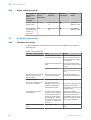
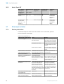
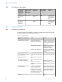
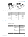
4.2 WT teach modes
Teach-in mode
for objects /
Teach-in mode
for objects
Teach-in time /
Teach-in time
Alignment /
Alignment
LED indicator /
LED indicator
Results /
Results
Single teach-in
pushbutton
Approx. 1.0 s Sensor to object
Ö
Sensing range is
adjusted accord‐
ing to object
ET: Connect pin 5
or gray wire to UV
for > 2 to < 4 s ().
> 2s Sensor to object
Ö
Sensing range is
adjusted accord‐
ing to object
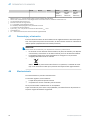
5 Troubleshooting
5.1 Troubleshooting
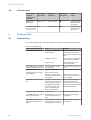
The Troubleshooting table indicates measures to be taken if the sensor stops working.
Table 1: Störungsbehebung
LED indicator/fault pattern Cause Measures
Green LED does not light up No voltage or voltage below
the limit values
Check the power supply,
check all electrical connec‐
tions (cables and plug connec‐
tions)
Voltage interruptions Ensure there is a stable power
supply without interruptions
Sensor is faulty If the power supply is OK,
replace the sensor
Green LED lights up, no output
signal when object is detected
Test input (Test) is not con‐
nected properly
See the note on connecting
the TI
Green LED flashes IO-Link communication -
Switching outputs not accord‐
ing to graphic C
IO-Link communication
Parameter settings made
manually, which deviate from
the standard
-
Initiate a factory reset. The
switching outputs are reset to
factory settings.
Yellow LEDs flash at the same
time
The sensor is not ready for
operation. The sensor will be
in the warming-up phase at
low ambient temperatures.
The sensor will have shut
down at excessively high
ambient temperatures.
At low ambient temperatures,
wait until the sensor has
warmed up. Ensure the sensor
cools down at excessively high
ambient temperatures.
Yellow LED flashes (only briefly) Teach-in mode Check the teach-in mode
Yellow LED lights up, no object
in the path of the beam
Distance between the sensor
and the background is too
short
Reduce the sensing range,
see graphic F
Object is in the path of the
beam, yellow LED does not
light up
Distance between the sensor
and the object is too long or
sensing range is set too short
Increase the sensing range,
see graphic F
4 CONFIGURATION
10
8018110.1BVZ / 2021-05-18 | SICK
Subject to change without notice

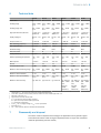
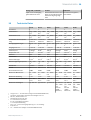
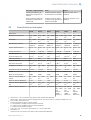
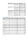
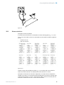
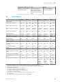
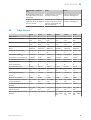
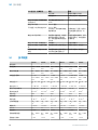
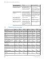
6 Technical data
-Bxx3x -Bxx4x -Bxx6x -Bxx1x -Bxx2x -Bxx5x
Laser class 1 1 1 1 1 1
Sensing range 100 ... 2500
mm
1
100 ... 1800
mm
1
100 ... 3800
mm
1
100 ... 1600
mm
1
100 ... 1400
mm
1
100 ... 1800
mm
1
Sensing range max. 50 ... 2500
mm
1
50 ... 1800
mm
1
50 ... 3800
mm
1
50 ... 1600
mm
1
50 ... 1400
mm
1
50 ... 1800
mm
1
Light spot diameter/distance < 14.0 mm /
2500 mm
< 12.0 mm /
1800 mm
< 18.0 mm /
3800 mm
< 11.0 mm /
1600 mm
<10.0 mm /
1400 mm
< 12.0 mm /
1800 mm
Supply voltage V
S
DC 10 ... 30
V
2
DC 10 ... 30
V
2
DC 10 ... 30
V
2
DC 10 ... 30
V
2
DC 10 ... 30
V
2
DC 10 ... 30
V
2
Output current I
max.
≤ 100 mA ≤ 100 mA ≤ 100 mA ≤ 100 mA ≤ 100 mA ≤ 100 mA
Max. switching frequency 1,000 Hz
3
30 Hz
3
100 Hz
3
1000 Hz
3
30 Hz
3
100 Hz
3
Max. response time 0.5 ms
4
16.7 ms
4
5 ms
4
0.5 ms
4
16.7 ms
4
5 ms
4
Enclosure rating IP67 IP67 IP67 IP67 IP67 IP67
Protection class III III III III III III
Circuit protection A, B, C
5
A, B, C
5
A, B, C
5
A, B, C
5
A, B, C
5
A, B, C
5
Ambient operating temperature -35 ... +50
°C
6
-35 ... +50
°C
6
-35 ... +50
°C
6
-35 ... +50
°C
6
-35 ... +50
°C
6
-35 ... +50
°C
6
Warm-up time <15 min <15 min <15 min <15 min <15 min <15 min
IO-Link 1.1 1.1 1.1 1.1 1.1 1.1
Communication mode COM2 COM2 COM2 COM2 COM2 COM2
Distance value measuring range 50 ... 2500
mm
50 ... 1800
mm
50 ... 3800
mm
50 ... 1600
mm
50 ... 1400
mm
50 ... 1800
mm
Distance value-resolution 1 mm 1 mm 1 mm 1 mm 1 mm 1 mm
Distance value reproducibility 2.3 ... 6.1
mm
78
0.9 ... 1.3
mm
78
1.1 ... 3.0
mm
78
2.7 ... 8.0
mm
78
1.1 ... 1.5
mm
78
1.2 ... 3.0
mm
78
Distance value-accuracy typ. ±15 mm typ. ±15 mm typ. ±15 mm typ. ±20 mm
(50 ... 1000
mm)
±15 mm
(1000 ...
1600 mm)
typ. ±20 mm
(50 ... 1000
mm)
±15 mm
(1000 ...
1400 mm)
typ. ±20 mm
(50 ... 1000
mm)
±15 mm
(1000 ...
1800 mm))
1
Object with 6 % ... 90 % remission (based on standard white DIN 5033)
2
Limit value; operation in short-circuit protection mains max. 8 A; residual ripple max. 5 V
ss
3
With light / dark ratio 1:1
4
Signal transit time with resistive load
5
A = U
V
-connections reverse polarity protected
B = inputs and output reverse-polarity protected
C = Interference suppression
6
As of T
U
= 45°C a supply voltage of V
max
= 24 V is permissible.
7
Equivalent to 1 σ.
8
6% ... 90% remission (based on standard white DIN 5033)
7 Disassembly and disposal
The sensor must be disposed of according to the applicable country-specific regula‐
tions. Efforts should be made during the disposal process to recycle the constituent
materials (particularly precious metals).
TECHNICAL DATA 6
8018110.1BVZ / 2021-05-18 | SICK
Subject to change without notice
11

NOTE
Disposal of batteries, electric and electronic devices
•
According to international directives, batteries, accumulators and electrical or
electronic devices must not be disposed of in general waste.
•
The owner is obliged by law to return this devices at the end of their life to the
respective public collection points.
•
WEEE: This symbol on the product, its package or in this document,
indicates that a product is subject to these regulations.
8 Maintenance
SICK sensors are maintenance-free.
We recommend doing the following regularly:
•
Clean the external lens surfaces
•
Check the screw connections and plug-in connections
No modifications may be made to devices.
Subject to change without notice. Specified product properties and technical data are
not written guarantees.
8 MAINTENANCE
12
8018110.1BVZ / 2021-05-18 | SICK
Subject to change without notice


Beschriebenes Produkt
PowerProx - WTT12L
Hersteller
SICK AG
Erwin-Sick-Str. 1
79183 Waldkirch
Deutschland
Rechtliche Hinweise
Dieses Werk ist urheberrechtlich geschützt. Die dadurch begründeten Rechte bleiben
bei der Firma SICK AG. Die Vervielfältigung des Werks oder von Teilen dieses Werks
ist nur in den Grenzen der gesetzlichen Bestimmungen des Urheberrechtsgesetzes
zulässig. Jede Änderung, Kürzung oder Übersetzung des Werks ohne ausdrückliche
schriftliche Zustimmung der Firma SICK AG ist untersagt.
Die in diesem Dokument genannten Marken sind Eigentum ihrer jeweiligen Inhaber.
© SICK AG. Alle Rechte vorbehalten.
Originaldokument
Dieses Dokument ist ein Originaldokument der SICK AG.
14
8018110.1BVZ / 2021-05-18 | SICK
Subject to change without notice

Inhalt
9 Allgemeine Sicherheitshinweise..................................................... 16
9.1 Sicherheitshinweise.................................................................................. 16
10 Produktbeschreibung....................................................................... 16
10.1 Bestimmungsgemäße Verwendung......................................................... 16
10.2 Maßzeichnungen...................................................................................... 17
10.3 Zusatzfunktionen...................................................................................... 17
11 Inbetriebnahme................................................................................. 18
11.1 Einsatzbedingungen prüfen:.................................................................... 18
11.2 Montage.................................................................................................... 18
11.3 Elektronik.................................................................................................. 19
11.4 Ausrichtung............................................................................................... 20
12 Konfiguration..................................................................................... 20
12.1 Einstellung................................................................................................. 20
12.2 WT Teach-Modi.......................................................................................... 22
13 Störungsbehebung............................................................................ 22
13.1 Störungsbehebung................................................................................... 22
14 Technische Daten.............................................................................. 23
15 Demontage und Entsorgung............................................................ 24
16 Wartung.............................................................................................. 24
INHALT
8018110.1BVZ / 2021-05-18 | SICK
Subject to change without notice
15

9 Allgemeine Sicherheitshinweise
9.1 Sicherheitshinweise
■
Vor der Inbetriebnahme die Betriebsanleitung lesen.
■
Anschluss, Montage und Einstellung nur durch Fachpersonal.
■
Kein Sicherheitsbauteil gemäß EU-Maschinenrichtlinie.
■
UL: Nur zur Verwendung in Anwendungen gemäß NFPA 79. Diese Geräte müssen
mit einer für 30V DC geeigneten 1A-Sicherung abgesichert werden. Von UL gelis‐
tete Adapter mit Anschlusskabeln sind verfügbar.
■
Gerät bei Inbetriebnahme vor Feuchte und Verunreinigung schützen.
■
Diese Betriebsanleitung enthält Informationen, die während des Lebenszyklus des
Sensors notwendig sind.
EN/IEC 60825-1:2014
IEC60825-1:2007
Laser
1
Maximale Pulsleistung: < 250 mW
Impulsdauer: 4 ns
Wellenlänge: 658 nm
Entspricht 21 CFR 1040.10
und 1040.11 mit Ausnahme von
Abweichungen nach
Laser-Hinweis 50, 24. Juni 2007
LASERKLASSE 1
ACHTUNG
ACHTUNG: Eingriffe oder Manipulationen oder nicht bestimmungsgemäße Verwendung
kann zu gefährlicher Belastung durch Laser-Lichtstrahlung führen.
The device must be supplied by a Class 2 source of supply.
UL Environmental Rating: Enclosure type 1
10 Produktbeschreibung
10.1 Bestimmungsgemäße Verwendung
Die WTT12L ist ein optoelektronischer Reflexions-Lichttaster (im Folgenden Sensor
genannt) und wird zum optischen, berührungslosen Erfassen von Sachen eingesetzt.
Bei jeder anderen Verwendung und bei Veränderungen am Produkt verfällt jeglicher
Gewährleistungsanspruch gegenüber der SICK AG.
9 ALLGEMEINE SICHERHEITSHINWEISE
16
8018110.1BVZ / 2021-05-18 | SICK
Subject to change without notice

10.2 Maßzeichnungen
WTT12L-X2xxx -X1xxx / -X3xxx
-Xxxx2 / -Xxxx4 -Xxxx1
-Xxxx3 / -Xxxx7 -Xxxx6 / -Xxxx8
1
2
7
6
7
9
8
3
4
5
20
(0.79)
44.2 (1.74)
31.9 (1.26)
6 (0.24)
44.2 (1.74)
31.9 (1.26)
6 (0.24)
Ø 4.2
(0.17)
Ø 4.2
(0.17)
49.6 (1.95)
5.1 (0.2)
48.7 (1.92)
61.6 (2.43)
47 (1.85)18.5 (0.73)
36.3 (1.43)
21.1
(0.83)
M12x1
36.5 (1.44)
4 (0.16)
5.1 (0.2)
48.7 (1.92)
4 (0.16)
36.5 (1.44)
6 (0.24)
8 (0.31)
18.3
(0.72)
18.3
(0.72)
Abbildung: Maßzeichnung WTT12L
1
Mitte Optikachse, Sender
2
Mitte Optikachse, Empfänger
3
Potentiometer / LED-Anzeige gelb: Status des empfangenen
Lichtstrahls
4
Potentiometer / LED-Anzeigen (grün): Power on
5
Potentiometer / LED-Anzeige gelb: Status des empfangenen
Lichtstrahls
6
Befestigungsbohrung D4,2 mm
7
Stecker M12, 4-polig oder Kabel
8
Potentiometer
9
Einfach-Teach-in-Taste
10.3 Zusatzfunktionen
Testeingang: Der Sensor WTT12L verfügt über einen Testeingang („TE“ oder „Test“ im
Anschlussschema [B]), mit dem der Sender ausgeschaltet und somit die ordnungsge‐
mäße Funktion des Sensors überprüft werden kann: Bei Verwendung von Leitungsdo‐
sen mit LED-Anzeigen ist darauf zu achten, dass der TE entsprechend belegt ist.
Es muss sich ein Objekt im Strahlengang befinden (Lichtempfang), Testeingang akti‐
vieren (siehe Anschlussschema [B], TE 24 V). Sende-LED wird abgeschaltet, bzw. es
wird simuliert, dass kein Objekt erkannt wird. Zur Überprüfung der Funktion Grafik C
heranziehen. Verhält sich der Schaltausgang nicht gemäß Grafik C, Einsatzbedingungen
prüfen. Siehe Abschnitt Fehlerdiagnose.
Der Sensor kann im Standard I/O-Modus (SIO) oder im IO-Link-Modus (IOL) verwendet
werden. Alle Automatisierungsfunktionen und sonstigen Parametereinstellungen sind
im IO-Link-Betrieb und im Standard I/O-Betrieb wirksam (Ausnahme: Zeitstempel). Im
Standard I/O-Betrieb Ausgabe der binären Schaltsignale über Pin 4 / schwarze Ader
bzw. über Pin 5 / graue Ader.
Die IO-Link Funktionalitäten bitte der beiliegenden Betriebsanleitung IO-Link Photo‐
electric Sensors entnehmen oder über www.sick.com unter der Geräte-Bestellnummer
downloaden.
PRODUKTBESCHREIBUNG 10
8018110.1BVZ / 2021-05-18 | SICK
Subject to change without notice
17

11 Inbetriebnahme
11.1 Einsatzbedingungen prüfen:
Einsatzbedingungen prüfen: Schaltabstand und Distanz zum Objekt bzw. Hintergrund
sowie Remissionsvermögen des Objektes mit dem zugehörigen Diagramm [vgl. H]
abgleichen (x = Schaltabstand, y = Mindestabstand zwischen Objekt und Hintergrund
in mm (Remission Objekt / Remission Hintergrund) (Remission: 6 % = schwarz, 90 % =
weiß (bezogen auf Standardweiß nach DIN 5033)).
Die minimale Distanz (= y) für die Hintergrundausblendung kann aus dem Diagramm
[vgl. H 15] wie folgt abgelesen werden:
Beispiel: x = 1000 mm, y = 20 mm. D. h. der Hintergrund wird ab einer Distanz von >
20 mm hinter dem Objekt ausgeblendet.
0
5
(0.2)
10
(0.39)
15
(0.59)
20
(0.79)
25
(0.98)
30
(1.18)
35
(1.38)
40
(1.57)
0
1
6%/90%
2
6%/90%
90%/90%
5
4
90%/90%
3
6%/90%
6
90%/90%
Min. distance from object to background in mm (inch)
1,000
(39.37)
2,000
(78.74)
3,000
(118.11)
4,000
(157.48)
Distance in mm (inch)
1) -Bxx3x: 6 % / 90 %
2) -Bxx3x: 90 % / 90 %
3) -Bxx6x: 6 % / 90 %
4) -Bxx6x: 90 % / 90 %
5) -Bxx4x: 6 % / 90 %
6) -Bxx4x: 90 % / 90 %
Abbildung: H-1
0
4
5
6
90%/90%
90%/90%
90%/90%
1
6%/90%
2
3
6%/90%
6%/90%
30
(1.18)
20
(0.79)
10
(0.39)
50
(1.97)
40
(1.57)
500
(19.69)
1,000
(39.37)
1,500
(59.06)
2,000
(78.74)
Min. distance from object to background in mm (inch)
Distance in mm (inch)
1) -Bxx1x: 6 % / 90 %
2) -Bxx1x: 90 % / 90 %
3) -Bxx5x: 6 % / 90 %
4) -Bxx5x: 90 % / 90 %
5) -Bxx2x: 6 % / 90 %
6) -Bxx2x: 90 % / 90 %
Abbildung: H-2
11.2 Montage
Den Sensor an einen geeigneten Befestigungswinkel montieren (siehe SICK-Zube‐
hör-Programm).
Maximal zulässiges Anzugsdrehmoment des Sensors von 0.8 Nm beachten.
Vorzugsrichtung des Objektes zum Sensor beachten [vgl. E].
11 INBETRIEBNAHME
18
8018110.1BVZ / 2021-05-18 | SICK
Subject to change without notice

Abbildung: E
11.3 Elektronik
Betrieb im Standard I/O-Modus:
Anschluss der Sensoren muss spannungsfrei (U
V
= 0 V) erfolgen. Je nach Anschlussart
sind die Informationen in den Grafiken [vgl. B] zu beachten:
– Steckeranschluss: Pinbelegung
– Leitung: Adernfarbe
Abbildung 6: B
Erst nach Anschluss aller elektrischen Verbindungen die Spannungsversorgung (U
V
> 0
V) anlegen bzw. einschalten. Am Sensor leuchtet die grüne Anzeige-LED.
Betrieb im IO-Link-Modus: Gerät an geeigneten IO-Link-Master anschließen und per
IODD / Funktionsblock im Master, bzw. in der Steuerung integrieren. Am Sensor blinkt
die grüne Anzeige-LED. IODD und Funktionsblock stehen unter www.sick.com unter der
Bestellnummer zum Download bereit.
Erläuterungen zum Anschlussschema (Grafik B):
INBETRIEBNAHME
11
8018110.1BVZ / 2021-05-18 | SICK
Subject to change without notice
19
A página está carregando...
A página está carregando...
A página está carregando...
A página está carregando...
A página está carregando...
A página está carregando...
A página está carregando...
A página está carregando...
A página está carregando...
A página está carregando...
A página está carregando...
A página está carregando...
A página está carregando...
A página está carregando...
A página está carregando...
A página está carregando...
A página está carregando...
A página está carregando...
A página está carregando...
A página está carregando...
A página está carregando...
A página está carregando...
A página está carregando...
A página está carregando...
A página está carregando...
A página está carregando...
A página está carregando...
A página está carregando...
A página está carregando...
A página está carregando...
A página está carregando...
A página está carregando...
A página está carregando...
A página está carregando...
A página está carregando...
A página está carregando...
A página está carregando...
A página está carregando...
A página está carregando...
A página está carregando...
A página está carregando...
A página está carregando...
A página está carregando...
A página está carregando...
A página está carregando...
A página está carregando...
A página está carregando...
A página está carregando...
A página está carregando...
A página está carregando...
A página está carregando...
A página está carregando...
A página está carregando...
A página está carregando...
A página está carregando...
A página está carregando...
A página está carregando...
A página está carregando...
A página está carregando...
A página está carregando...
A página está carregando...
A página está carregando...
A página está carregando...
A página está carregando...
A página está carregando...
A página está carregando...
A página está carregando...
A página está carregando...
A página está carregando...
A página está carregando...
A página está carregando...
A página está carregando...
A página está carregando...
A página está carregando...
A página está carregando...
A página está carregando...
A página está carregando...
A página está carregando...
A página está carregando...
A página está carregando...
A página está carregando...
A página está carregando...
A página está carregando...
A página está carregando...
A página está carregando...
A página está carregando...
A página está carregando...
A página está carregando...
A página está carregando...
-
 1
1
-
 2
2
-
 3
3
-
 4
4
-
 5
5
-
 6
6
-
 7
7
-
 8
8
-
 9
9
-
 10
10
-
 11
11
-
 12
12
-
 13
13
-
 14
14
-
 15
15
-
 16
16
-
 17
17
-
 18
18
-
 19
19
-
 20
20
-
 21
21
-
 22
22
-
 23
23
-
 24
24
-
 25
25
-
 26
26
-
 27
27
-
 28
28
-
 29
29
-
 30
30
-
 31
31
-
 32
32
-
 33
33
-
 34
34
-
 35
35
-
 36
36
-
 37
37
-
 38
38
-
 39
39
-
 40
40
-
 41
41
-
 42
42
-
 43
43
-
 44
44
-
 45
45
-
 46
46
-
 47
47
-
 48
48
-
 49
49
-
 50
50
-
 51
51
-
 52
52
-
 53
53
-
 54
54
-
 55
55
-
 56
56
-
 57
57
-
 58
58
-
 59
59
-
 60
60
-
 61
61
-
 62
62
-
 63
63
-
 64
64
-
 65
65
-
 66
66
-
 67
67
-
 68
68
-
 69
69
-
 70
70
-
 71
71
-
 72
72
-
 73
73
-
 74
74
-
 75
75
-
 76
76
-
 77
77
-
 78
78
-
 79
79
-
 80
80
-
 81
81
-
 82
82
-
 83
83
-
 84
84
-
 85
85
-
 86
86
-
 87
87
-
 88
88
-
 89
89
-
 90
90
-
 91
91
-
 92
92
-
 93
93
-
 94
94
-
 95
95
-
 96
96
-
 97
97
-
 98
98
-
 99
99
-
 100
100
-
 101
101
-
 102
102
-
 103
103
-
 104
104
-
 105
105
-
 106
106
-
 107
107
-
 108
108
-
 109
109


SICK PowerProx - WTT12L MultiTask photoelectric sensor Instruções de operação
- Tipo
- Instruções de operação
em outras línguas
- español: SICK PowerProx - WTT12L MultiTask photoelectric sensor Instrucciones de operación
- français: SICK PowerProx - WTT12L MultiTask photoelectric sensor Mode d'emploi
- italiano: SICK PowerProx - WTT12L MultiTask photoelectric sensor Istruzioni per l'uso
- English: SICK PowerProx - WTT12L MultiTask photoelectric sensor Operating instructions
- русский: SICK PowerProx - WTT12L MultiTask photoelectric sensor Инструкция по эксплуатации
- Deutsch: SICK PowerProx - WTT12L MultiTask photoelectric sensor Bedienungsanleitung
- 日本語: SICK PowerProx - WTT12L MultiTask photoelectric sensor 取扱説明書
Artigos relacionados
-
SICK PowerProx - WTT12L Photoelectric sensors Instruções de operação
-
-
-
-
-
-
-
-
-
