Brandt TG612MS1 Manual do proprietário
- Categoria
- Fogões
- Tipo
- Manual do proprietário

EN GUIDE FOR INSTALLATION AND USE
PT GUIA DE INSTALAÇÃO E DE UTILIZAÇÃO
Cooking Hob
Placa de cozinha

2
As part of our commitment to constantly improving our products, we reserve the
right to make changes to them based on technical advances to their technical and
functional features and appearance.
Important :
Before installing and using your appliance, please carefully read this Guide to
Installation and Use, which will allow you to quickly familiarise yourself with its
operation.
Dear Customer,
You have just acquired a
BBRRAANNDDTT
hob and we would like to thank
you.
We have invested all our dedication and know-how in this appliance
so that it would best meet your needs. With innovation and
performance, we designed it to be always easy to use.
In the
BBRRAANNDDTT
product range, you will also find a wide choice of
ovens, microwaves, ventilation hoods, cookers, dishwashers,
washing machines, , fridges and freezers, that you can coordinate
with your new
BBRRAANNDDTT
hob.
Visit our website
wwwwww..bbrraannddtt..ccoomm
where you will find all of our
products, as well as useful and complementary information
BBRRAANNDDTT
EN
02
PT
21

3
EN
••
Safety recommendations
____________________________________
4
••
Environmental protection
____________________________________
5
••
Description of your appliance
________________________________
6
1 / INSTALLING YOUR APPLIANCE
••
Proper positioning
_________________________________________
7
••
Flush mounting
____________________________________________
7
••
Tips for flush mounting
_____________________________________
8
••
Electrical connection
_______________________________________
8
••
Gas connection
____________________________________________
9
••
Changing the gas supply
____________________________________
11
2 / USING YOUR APPLIANCE
••
Description of the top
_______________________________________
15
••
Switching on gas burners
___________________________________
16
••
Cookware to be used with gas burners
________________________
17
••
Cookware for electric plate
__________________________________
18
••
Switching on the electric plate
______________________________
18
3 / DAILY CARE OF YOUR APPLIANCE
••
Maintaining your appliance
__________________________________
19
4 / SPECIAL MESSAGES, DIFFICULTIES
••
During operation
___________________________________________
20
5 / COOKING CHART
••
Gas cooking guide
_________________________________________
21
••
Electric cooking guide
______________________________________
21
6 / AFTER-SALES SERVICE
••
Repairs
___________________________________________________
44
••
Customer relations
_________________________________________
44
TABLE OF CONTENTS

4
SAFETY RECOMMENDATIONS
— We have designed this cooking hob for use
by private persons in their homes.
— This appliance must be installed in
compliance with currently applicable
regulations and used only in a well-ventilated
location. Consult this guide before installing
and using your appliance.
— All cooking should take place under your
surveillance.
— These cooking hobs are meant to be used
exclusively for cooking beverages and
foodstuffs and do not contain any asbestos-
based materials.
— This appliance is not connected to a
combustion by-product disposal system. It
must be installed and connected in
compliance with all applicable laws. Special
attention should be given to applicable
regulations concerning ventilation.
— Do not store
CCLLEEAANNIINNGG
products or
FFLLAAMMMMAABBLLEE
products (aerosol cans or
containers under pressure, as well as papers,
cookbooks, etc.) in the cabinet underneath
your cooking hob.
— If you use a drawer located under the hob,
we recommend that you avoid storing in it
items that are heat sensitive (plastic, papers,
aerosol cans, etc.).
— Your hob should be disconnected from
power and fuel supplies (electricity and gas)
before any repairs.
— When you connect the power cables of any
electrical appliances plugged in close to the
hob, ensure that they are not in contact with
the cooking zones.
— As a safety measure, do not forget to close
the general supply tap for gas distributed by
pipe or the tap of the tank for butane or
propane gas after use.
— The
CCEE
compliance designation is affixed to
these hobs.
— Installation should only be performed by
installers and qualified technicians.
— Before installation, ensure that the
conditions of local distribution (gas type and
pressure) and the settings of the appliance
are compatible.
——
This hob is compliant with standard
EN 60335-2-6 relating to the heating of
cabinets and the Class 3 standard with regard
to installation (as per standard EN 30-1-1).
••
Warning
The required settings for the hob are
written on a sticker located in the plastic
bag, as well as on the packaging.
In order to easily locate the reference
information for your appliance, we
recommend that you note them on the
“After-Sales Service Department and
Customer Relations” page (this page also
explains to you where to find this
information on your appliance).
In the event that a crack becomes visible in
the glass worktop, immediately unplug the
appliance and contact the After-Sales
Service department.
SAFETY RECOMMENDATIONS

5
EN
ENVIRONMENTAL PROTECTION
••
— This appliance’s packaging material is
recyclable. Help recycle it and protect the
environment by dropping it off in the
municipal receptacles provided for this
purpose.
— Your appliance also contains a
great amount of recyclable
material. It is marked with this
label to indicate the used
appliances that should not be
mixed with other waste. This way,
the appliance recycling organised
by your manufacturer will be done under the
best possible conditions, in compliance with
European Directive 2002/96/EC on Waste
Electrical and Electronic Equipment. Contact
your town hall or your retailer for the used
appliance collection points closest to your
home.
— We thank you doing your part to protect the
environment.
ENVIRONMENTAL PROTECTION

6
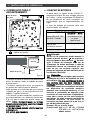
••
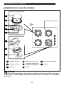
DESCRIPTION OF YOUR HOB
Tip
This Guide to Installation and Use is valid for several models. Minor differences in
details and fittings may emerge between your appliance and the descriptions provided.
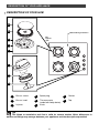
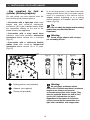
DESCRIPTION OF YOUR APPLIANCE
A
B
Burner covers
Burner head
Injector
C
D
Spark plug
Thermocouple
(model with safety device)
Knob
E
G
H
Gasket
Tap
F
Hob model: 4 gas burners
Pan
support
grid
A
B
C
D
E
F
G
H

7
EN
••
PROPER POSITIONING
Your appliance shoud be built in the surface
of a support cabinet that is a minimum of
three cm thick, made of a material that resists
heat or that is covered with such a material.
So as not to disturb movement of cooking
utensils, there should not be to the right or
left or back any obstacle within 30 cm of the
hob.
if a horizontal divider wall is positioned under
the hob, it should be placed between 10 cm
and 15 cm away from the top of the work top.
In any event, do not store aerosol cans or
containers under pressure in any
compartment that may exist under the hob
(See
“
Safety Recommendations
”
chapter).
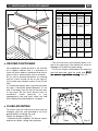
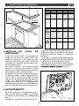
FLUSH MOUNTING
To ensure that the hob and the work top are
leaktight, glue the seal provided in the front
pocket before installing the hob:
Follow the diagram
(Fig. 01)
.
— Remove the pan supports, the burner covers
and burner heads, noting their positions.
— Turn the hob over and carefully place it on
top of the opening in the cabinet so asnot to
damage the knobs and spark plugs.
— To ensure a tight seal between the housing
and the work top, glue the foam seal
aalloonngg
tthhee eexxtteerriioorr eeddggee ooff tthhee hhoouussiinngg
(Fig. 02
).
••
48 cm mini
3 cm m
ini
30 cm mini
56 cm / 26,5 cm
30 cm mini
5,8 cm
m
ini
70 cm mini
Fig. 01
1 / INSTALLING YOUR APPLIANCE
Fig. 02
Housing
Seal
APPLIANCE
Cut
cabinet
standard
Cut
cabinet
standard
Dimensions
total
above
the work
top
Dimensions
total
below
the work
top
Width
56 cm
26,5 cm
71 cm
31 cm
55,4 cm
26 cm
Depth
49 cm
49 cm
52,2 cm
51 cm
47 cm
47 cm
Thickness
According
to cabinet
According
to cabinet
5 cm
5 cm
5,1 cm
5,1 cm
Model
60 cm
30 cm
60 cm
30 cm
60 cm
30 cm

8
— Place your hob in the opening of the
support cabinet, carefully pulling the table
toward you.
— Reposition the burner heads, burner covers
and pan supports on the hob.
Connect your hob to the gas supply (See
“Gas Connection” chapter) and to the power
supply (See “Electrical Connection” chapter).
— If you wish, you can immobilise the hob
using the four mounting brackets delivered
with a screw
(Fig. 02)
to attach them to the
four corners of the housing.
YYoouu mmuusstt uussee tthhee
hhoolleess pprroovviiddeedd ffoorr tthhiiss ppuurrppoossee,, aaccccoorrddiinngg ttoo
tthhee ddiiaaggrraamm aabboovvee
(Fig. 01)
..
—
SSttoopp ssccrreewwiinngg wwhheenn tthhee mmoouunnttiinngg bbrraacckkeett
ssttaarrttss ttoo bbeeccoommee ddeeffoorrmmeedd..
DDoo nnoott uussee aa ssccrreewwddrriivveerr
.
••
TIPS FOR FLUSH MOUNTING
••
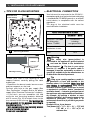
ELECTRICAL CONNECTION
Your hob must be connected to the 220-240 V
~
monophase grid via a 2-pole electrical outlet plug
+ standardised CEI 60083 ground or an all-pole
cut-off device, in compliance with the current
regulations.
The plug of the electrical outlet must be
accessible after installation.
Warning
The safety wire (green/yellow) is
connected to the appliance’s ground terminal
and must be linked to the installation’s
ground terminal . The fuse in your set-up
must be 10 amperes. If the power cable is
damaged, it must be replaced by a cable or a
special kit available from the manufacturer or
its After-Sales Service Department.
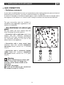
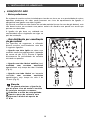
Tip
Using a gas cooking appliance results in
the generation of heat and humidity in the
location where it is installed.
MMaakkee ssuurree tthhaatt
yyoouurr kkiittcchheenn iiss wweellll--vveennttiillaatteedd::
keep natural
ventilation orifices in your home open or install
a mechanical ventilation device (mechanical
ventilation hood). — Intensive, prolonged use of
the appliance may require additional ventilation;
for example, by opening a window or more
effective ventilation ; by increasing power to the
mechanical ventilation, if you have it. (A
minimum air flow of 2 m
3
/h per kW of gas power
is required).
Example: 60 cm, 4 gas burners
Total power: 0,85 + 1,5 + 2,3 + 3,1 = 7,75 kW
7,75 kW x 2 = 15,5 m
3
/H of
minimum flow.
CC
AABBLLEE CCRROOSSSS
--
SSEECCTTIIOONN TTOO BBEE UUSSEEDD
H05V2V2F -T90 cable
Ref. After-sales
service: 77x9060
Cross-section of
conductors in mm
2
Fuse
222200--224400 VV
~~
-- 5500 HHzz
3 conductors
including
one ground wire
1
10 A
1 / INSTALLING YOUR APPLIANCE
A
A
A A
Fig. 01
Fig. 02
Mounting brackets
Screws
Underside view
of the housing
Mounting brackets
A
Cabinet

9
EN
The gas connection must be installed in
compliance with applicable regulations in the
country of installation.
• Gas distributed via natural gas
pipes
For your safety, you must choose from the
three following connection options:
— Connection with a rigid pipe
made from
copper and with screw-on mechanical
connectors (G1/2 gas standard mark). Make
the connection directly to the end of the
elbow fitted on the appliance.
— Connection with a wavy metal hose
(stainless steel) with screw-on
mechanical
connectors
whose service life is unlimited
(Fig. A).
— Connection with a reinforced flexible
rubber hose
with screw-on
mechanical
connectors
whose service life is 10 years
(Fig. B).
Warning
When connecting your hob’s gas
supply, if you have to change the
direction of the elbow fitted on the
appliance:
①①
Change the gasket.
②②
Screw on the elbow’s nut, careful not
to exceed a torque of 17 N.m.
GAS CONNECTION
•
Preliminary comments
If your hob is installed above an oven or if proximity to other heating elements poses a threat of
overheating the connection, you must insulate the cable in a rigid pipe.
If a hose or soft pipe (in the case of butane gas) is used, it should not come into contact with a
moving part of the cabinet, nor should it pass through a location that may become blocked.
••
1 / INSTALLING YOUR APPLIANCE
Fig. A
Fig. B

10
• Gas supplied by tank or
cylinder (butane/propane)
For your safety, you must choose from the
three following connection options:
— Connection with a rigid pipe
made from
copper and with screw-on mechanical
connectors (G1/2 gas standard mark). Make
the connection directly to the end of the
elbow fitted on the appliance.
— Connection with a wavy metal hose
(stainless steel) with screw-on
mechanical
connectors
whose service life is unlimited
(Fig. 01).
— Connection with a reinforced flexible
rubber hose
with screw-on
mechanical
connectors
whose service life is 10 years
(Fig. 02).
A
B
Sealing washer (not provided)
Adaptor (not supplied)
Clamp (not provided)
C
Warning
All soft pipes and hoses whose
service life is limited must have a maximum
length of two meters and must be
accessible along their entire length. They
must be replaced before the end of their
service life (indicated on the pipe).
Regardless of the means of connection
chosen, ensure that the connection is air
tight, after installation, with soapy water.
In an existing system, a soft pipe fitted with
clamps whose service life is five years may be
used. It is necessary in this case to use an
adaptor without forgetting to fit a sealing
washer between the adaptor and the hob’s
elbow.
(Fig. 03).
Tip
You can obtain the adaptor and the sealing
washer from your After-Sales Service
Department.
Warning
Screw on the adaptor with a torque
not exceeding 25 N.m.
1 / INSTALLING YOUR APPLIANCE
Fig. 01
Fig. 02
Fig. 03
A
B
C

11
EN
11
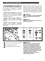
CHANGING THE GAS SUPPLY
Warning
Your appliance is sold pre-set for
natural gas.
The injectors required for adaption to
butane/propane can be found in the plastic
bag containing this guide.
Each time you change the gas supply, you
must complete the following:
— Adapt the gas connection
— Change the injectors
— Adjust the hob connections.
•
AAddaapptt tthhee ggaass ccoonnnneeccttiioonn
:
Refer to the
“Gas Connection” section.
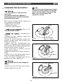
•
CChhaannggee tthhee iinnjjeeccttoorrss
, proceeding as
follows:
—
Remove the pan supports, heads and
covers from all burners.
—
Using the wrench provided, unscrew the
injectors located under each crucible and
remove them
(Fig. 01).
—
replace with the corresponding gas
injectors, in compliance with the positionning
of the injectors and the table of gas properties
at the end of this section ; to do so:
—
First screw them in manually until the
injector locks into place.
—
Apply the wrench to the injector as far as it
will go.
—
Draw a line on the burner plate using a
pencil at the place indicated
(Fig. 02).
—
Turn the wrench clockwise until the line
appears on the other side
(Fig. 03).
Warning
Exceeding this limit may damage the
product.
-
Reposition the burner heads, burner covers
and pan supports on the hob.
••
Tip
Each time you change the gas supply,
tick the box corresponding to the new gas
level on the label found in the plastic bag.
Refer to the corresponding “Gas
Connection” section.
Fig. 02
Fig. 03
Line
Line
Wrench
Wrench
Fig. 01
Wrench
Injector
Crucible
1 / INSTALLING YOUR APPLIANCE

12
•
AAddjjuusstt tthhee hhoobb ccoonnnneeccttiioonnss
: they are
located underneath the knobs
(Fig. 04)
.
—
Proceed one tap at a time.
—
Remove the knobs and the gaskets by
pulling them up.
- Switching from natural gas to
butane/propane gas
-
With a small flat-head screwdriver,
ssccrreeww iinn
aallll tthhee wwaayy
the brass (yellow) burner power
screws
(Fig. 05),
iinn aa cclloocckkwwiissee ddiirreeccttiioonn..
-
Replace the gaskets and the knobs, paying
careful attention to their direction and
ensuring that the knobs are pushed in all the
way.
- Switching from butane/propane gas to
natural gas
-
Unscrew the brass (yellow) burner power
screws
(Fig. 05)
, using a small flat-head
screwdriver,
ttuurrnn ttwwiiccee ccoouunntteerrcclloocckkwwiissee..
-
Replace the knob.
-
Light the burner in maximum heat mode,
then turn down to reduced heat mode.
-
Remove the knob again, then turn the
burner power screws
cclloocckkwwiissee
until it
reaches the lowest possible setting that does
not extinguish the flame.
-
Replace the gasket and knob.
-
Make several attempts to shift from the
maximum flow rate to the minimum
:: tthhee ffllaammee
sshhoouulldd nnoott ggoo oouutt
; if it does, unscrew the
burner power screw so as to obtain good
flame retention during these position
switches.
-
Reposition the burner heads, burner covers
and pan supports on the hob.
1 / INSTALLING YOUR APPLIANCE
Fig. 05
Tap axis
Burner power
adjustment screw
Fig. 05
Tap axis
Burner power
adjustment screw
Knob
Ring
Gasket
Tap
Fig. 04

13
EN
•
Markings on the injectors
The adjacent table shows where the injectors
are positioned on your appliance according to
the type of gas used.
Each number is marked on the injector.
MMAARRKKIINNGGSS OONN TTHHEE IINNJJEECCTTOORRSS
MMOODDEELLSS**
Example:
Injector marking 95
**
SSeeee ““DDeessccrriippttiioonn ooff tthhee TToopp”” cchhaapptteerr
95
1 / INSTALLING YOUR APPLIANCE
6600ccmm HHoobb 33 ggaass bbuurrnneerrss ++ 11 eelleeccttrriicc ppllaattee
6600 ccmm HHoobb 44 ggaass bbuurrnneerrss
3300 ccmm HHoobb 22 ggaass bbuurrnneerrss
Natural Gas
137
94
Butane gas/
Propane
88A
62
Natural Gas
94 1R
137 6A
Gaz butane/
Propane
62 7R
88A 45
Natural Gas
1R
137 6A
Butane gas/
Propane
7R
88A 45

14
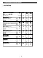
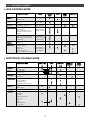
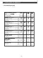
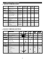
•Gas properties
1 / INSTALLING YOUR APPLIANCE
AApppplliiaannccee iinntteennddeedd ttoo bbee iinnssttaalllleedd iinn:: BBuuttaannee PPrrooppaannee GGaass GGaass
nnaattuurraall nnaattuurraall
GGBB -- PPTT..............................................ccaatt :: IIII22HH33++
G30 G31 G20 G25
Hourly rate below: 28-30 mbar 37 mbar 20 mbar 25 mbar
at 15°C under 1013 mbars
HH
IIGGHH
--
SSPPEEEEDD BBUURRNNEERR
Marking engraved on injector
77RR 77RR 11RR 11RR
Nominal heat release rate (kW) 2,15 2,15 2,20 2,25
Reduced heat release rate (with/without safety)(kW) 0,830 0,870 0,870
Hourly rate (g/h) 156 154
Hourly rate (l/h) 209 249
SS
UUPPEERR
--
FFAASSTT BBUURRNNEERR
Marking engraved on injector
8888AA 8888AA 113377 113377
Nominal heat release rate (kW) 3,10 3,10 3,10 3,10
Reduced heat release rate (with/without safety)(kW) 0,830 0,870 0,870
Hourly rate (g/h) 225 221
Hourly rate (l/h) 295 343
SS
EEMMII
--
FFAASSTT BBUURRNNEERR
Marking engraved on injector
6622 6622 9944 9944
Nominal heat release rate (kW) 1,50 1,50 1,50 1,50
Reduced heat release rate (with/without safety)(kW) 0,620 0,615 0,615
Hourly rate (g/h) 109 107
Hourly rate (l/h) 143 166
AA
UUXXIILLIIAARRYY BBUURRNNEERR
Marking engraved on injector
4455 4455 66AA 66AA
Débito calorífico nominal (kW) 0,70 0,70 0,85 0,85
Reduced heat release rate (with/without safety)(kW) 0,300 0,350 0,350
Hourly rate (g/h) 51 50
Hourly rate (l/h) 81 94
HH
OOBB
44
GGAASS BBUURRNNEERRSS
Total heat release rate (kW) 7,45 7,45 7,65 7,70
Maximum flow rate (g/h) 541 532
(l/h) 728 852
HH
OOBB
33++11
EELLEECCTTRRIICC PPLLAATTEE
11550000 WW
WWIITTHH SSUUPPEERR FFAASSTT
Total heat release rate (kW) 5,95 5,95 6,15 6,20
Maximum flow rate (g/h) 432 425
(l/h) 585 686
HH
OOBB
22
GGAASS BBUURRNNEERRSS
Total heat release rate (kW) 4,60 4,60 4,60 4,60
Maximum flow rate (g/h) 334 328
(l/h) 438 509

15
EN
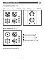
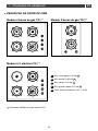
DESCRIPTION OF THE TOP
••
(
**
) Power obtained with natural gas G20
2 / USING YOUR APPLIANCE
Hob model: 4 gas burners TG*/*
Hob model: 2 gas burners TG*/*
Model: 3+1 electric TG*/*
A
B
C
D
E
Semi-fast burner 1.50 kW
((**))
Auxiliary burner 0.85 kW
((**))
High-speed burner 2.20 kW
((**))
Super-fast burner 3.10 kW
((**))
Electric plate diameter 145 - 1.5 kW
A
D
D
E D
B
D
A C
B

16
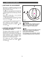
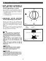
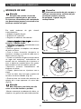
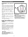
SWITCHING ON GAS BURNERS
Each burner is supplied by a tap which can be
opened by pressing it and turning it in in a
counterclockwise motion.
The “
●” point corresponds to closing the tap.
— Choose the desired burner by using the
symbols located near the knobs (e.g.: rear left
burner ).
Your hob is fitted with a burner-lighting
system built into the knobs.
— To light a burner, press on the knob and turn
it in a counterclockwise direction to the
maximum setting .
— Continue to press on the knob to produce a
series of sparks until the burner lights.
The setting for more moderate flame
intensities are between the symbol and
the symbol .
HOB WITH GAS SECURITY DEVICE
(according to model)
The burner safety measure is a metal rod
located directly to the side of the flame.
Each burner is controlled by a tap fitted with
a safety system that, in the event of accidental
flame extinction (spills, draughts, etc.),
quickly and automatically cuts the gas supply
and prevents it from being released.
The setting for more moderate flame
intensities are between the symbol and
the symbol .
••
••
2 / USING YOUR APPLIANCE
Fig. 01
Warning
— Hold the knob completely pressed
down for a few seconds after the flame
appears to trigger the safety system.
Tip
When a knob becomes difficult to turn,
do not force it. Request an emergency
service call for the installer.
If the flame goes out accidentally, reignite
normally following the starter instructions.

17
EN
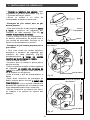
••
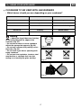
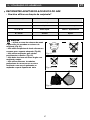
COOKWARE TO BE USED WITH GAS BURNERS
•
Which burner should you use depending on your cookware?
Warning
— Adjust the ring of flames so that they
do not extend beyond the edges of the
cookware (Fig. 01).
— Do not use concave or convex cookware
without the appropriate supports (Fig. 02).
— Do not use cookware that partially covers
the knobs (Fig. 03).
— Do not leave a gas burner operating with
empty cookware.
— Do not use heat regulators, toasters, steel
meat broilers or stewpots that have feet
resting on or touching the glass worktop
Diameter of the cookware
18 to 28 cm
16 to 22 cm
12 to 20 cm
8 to 14 cm
Diameter of the cookware
High-speed
speed
Semi-fast
Auxiliary
Use
Searing foods
Sauces - Reheating
Gentle simmer
2 / USING YOUR APPLIANCE
GGOOOODD
BBAADD
CCOONNVVEEXX
CCOONNCCAAVVEE
Fig. 01
Fig. 02
Fig. 03

18
MOST SUITABLE COOKWARE TO
BE USED WITH THE ELECTRIC
PLATE (depending on model)
Use cookware with flat bottoms that are
perfectly flush with the surface of the burner:
— in stainless steel with a thick, tri-metal or
“sandwich” bottom,
— in aluminium with a thick (smooth) bottom,
— in enamelled steel.
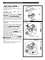
SWITCHING ON THE ELECTRIC
PLATE (depending on the model)
Position the knob on the marking that
corresponds to the desired type of cooking
(Fig. 01)
(see cooking guide at the end of this
guide). The cooking zone’s power indicator
lights up.
Upon first use, allow the plate to heat up with
no cookware at maximum power for 3
minutes to harden the coating.
Tip
—
Use cookware of an appropriate
size: the diameter of the bottom of the
cookware should be equal to or greater
than the diameter of the electric cooking
plate (Fig. 02).
—
When cooking is nearly finished, turn the
knob to the “O” off position to take
advantage of the heat accumulated in the
plate.
—
Use a lid on your cookware as often as
possible to reduce the loss of heat by
evaporation.
Warning
Do not operate an electric cooking
plate without cookware (except during
initial use) or with an empty pot.
Warning
The electric plate will remain hot for a
certain time after the knob has been turned
to the “O” position. Do not touch this zone
because there is a risk of burning.
22 //
USING YOUR APPLIANCE
••
••
YES
NO
Fig. 01
Fig. 02
Power
indicator

19
EN
PPRROODDUUCCTTSS//AACCCCEESSSSOORRIIEESS
TTOO BBEE UUSSEEDD
. Small, hard-bristled brush.
. Safety pin
. Gentle scrubbing cream
. Cleaning sponge
. Commercially available
restorative product.
- Cleaning sponge.
- Special vitroceramic glass
products (e.g.: Cera-clean).
Warning
Never clean your appliance while it is in operation. Set all the electric and gas
controls to zero.
Tip
— It is better to clean the parts of the hob by hand rather than in the dishwasher.
— Do not use an abrasive sponge to clean your hob.
— Do not use steam cleaning.
MAINTAINING YOUR APPLIANCE
••
WWHHAATT TTOO DDOO
In the event that the spark plugs become
soiled, clean them using a small, hard-
bristled brush (non-metallic).
The gas injector is located in the centre of
the burner in the shape of a dish. Be
careful not to obstruct it during cleaning,
as this will undermine the performance of
your hob. In the event of obstruction, use a
safety pin to unclog the injector.
If tough stains occur, use a non-abrasive
cream, then rinse with clean water.
Carefully wipe each part of the burner
before using your hob again.
- The heating plate is protected by a black
coating, so you should avoid using any
abrasive products. After each use, wipe it
down with a thick cloth.
- If the plate rusts, remove it and restore
the black coating using a commercially
available high-temperature restorative
product.
- Clean with warm water and then wipe.
For tough stains, use products designed
for vitroceramic glass.
MMAAIINNTTEENNAANNCCEE............
Of the spark plugs
and injectors
Of the pan supports
and gas burners
Of the electric plate
Of the glass
worktop
3 / DAILY CARE OF YOUR APPLIANCE
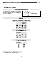
To keep your appliance in good working order, we recommend that you use Clearit household
products.
CClleeaarriitt
offers you professional products and adapted solutions for the daily upkeep of your
household and kitchen appliances.
You may find them in conventional retail outlets, along with a complete line of by-products and
consumables.
PPrrooffeessssiioonnaall eexxppeerrttiissee ffoorr tthhee ggeenneerraall ppuubblliicc

20
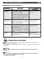
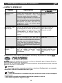
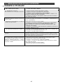
DURING OPERATION
••
YOU OBSERVE THAT: WHAT YOU SHOULD DO:
• Lighting the burners:
There are no sparks when you press the
knobs.
•
When you press on a knob, there are
sparks on all of the burners simultaneously.
•
In reduced heat mode, the burner goes
out or the flames remain high.
•
The flames look irregular or uneven.
•
During cooking, the knobs become hot.
If the hob has a gas safety device: during
lighting, the flames light, then go out as
soon as the knob is released.
. Check the electrical connection of your appliance.
. Check that the spark plugs are clean
. Check that the burners are clean and properly assembled
. If the hob is attached to the work top, check that the mounting brackets
are not deformed.
. Check that the gaskets under the knobs are not coming out of their
lodging.
This is normal. The lighting function is centralised and controls all of the
burners simultaneously.
. Avoid strong air currents in the room.
. Check that the gas type being used corresponds to the injectors
installed (Read about markings on the injectors in the “Changing the Gas
Supply” chapter).
Reminder: The cooking hobs are sold pre-set for use with network gas
(natural gas).
. Check that the burner power screws are properly set (See the
“Changing the Gas Supply” chapter).
. Check the cleanliness of the burners and injectors under the burners,
the assembly of the burners, etc...
. Check that there is enough gas in the bottle.
. Use small saucepans on the burners located closest to the knobs. Large
cookware should be used on the largest burners, which are farther away
from knobs. Properly place the saucepan in the centre of the burner. It
should not spill over onto the knobs.
. Press firmly down on the knobs and hold them down for a few seconds
after the appearance of flames.
. Check that the parts of the burner are correctly mounted.
. Check that the gaskets under the knobs are not coming out of their
lodging.
. Avoid strong draughts in the room.
. Light your burner before placing your saucepan on it.
4 / SPECIAL MESSAGES, DIFFICULTIES
EN
A página está carregando ...
A página está carregando ...
A página está carregando ...
A página está carregando ...
A página está carregando ...
A página está carregando ...
A página está carregando ...
A página está carregando ...
A página está carregando ...
A página está carregando ...
A página está carregando ...
A página está carregando ...
A página está carregando ...
A página está carregando ...
A página está carregando ...
A página está carregando ...
A página está carregando ...
A página está carregando ...
A página está carregando ...
A página está carregando ...
A página está carregando ...
A página está carregando ...
A página está carregando ...
A página está carregando ...
-
 1
1
-
 2
2
-
 3
3
-
 4
4
-
 5
5
-
 6
6
-
 7
7
-
 8
8
-
 9
9
-
 10
10
-
 11
11
-
 12
12
-
 13
13
-
 14
14
-
 15
15
-
 16
16
-
 17
17
-
 18
18
-
 19
19
-
 20
20
-
 21
21
-
 22
22
-
 23
23
-
 24
24
-
 25
25
-
 26
26
-
 27
27
-
 28
28
-
 29
29
-
 30
30
-
 31
31
-
 32
32
-
 33
33
-
 34
34
-
 35
35
-
 36
36
-
 37
37
-
 38
38
-
 39
39
-
 40
40
-
 41
41
-
 42
42
-
 43
43
-
 44
44


Brandt TG612MS1 Manual do proprietário
- Categoria
- Fogões
- Tipo
- Manual do proprietário
em outros idiomas
- English: Brandt TG612MS1 Owner's manual


