Greenlee FG01 G-Series Smart Pull Manual do usuário
- Tipo
- Manual do usuário

INSTRUCTION MANUAL
MANUEL D’INSTRUCTIONS
Read and understand all of the instructions and
safety information in this manual before operating
or servicing this tool.
Veuillez lire et comprendre toutes les
instructions et informations de sécurité de
ce manuel avant d’utiliser cet outil ou d’effectuer
son entretien.
Register this product at www2.greenlee.com/smartpullregistration
Enregistrez ce produit sur www2.greenlee.com/smartpullregistration
52080178 REV 2 © 2017 Greenlee Textron Inc. 11/17
FG01 G-Series Smart Pull
Smart Pull FG01 sérieG
Français .........13–20

FG01 G-Series Smart Pull
Greenlee / A Textron Company 4455 Boeing Dr. • Rockford, IL 61109-2988 USA • 815-397-7070
2
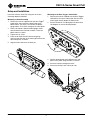
Description
The Greenlee FG01 G-Series Smart Pull is a cable puller
accessory intended to monitor the force developed
when cable is pulled into conduit. The FG01 includes
provisions for mounting of the Ultra Tugger
®
Cable
Puller and the Ultra Tugger
®
boom and G6 Turbo
®
Puller.
In order to use the FG01 with other cable pullers, it
must be installed to withstand the resistance of the rope
rolling across the ve rollers.
Contains Transmitter Module FCC ID: T9JRN41-3
This device complies with Part 15 of the FCC Rules.
Operation is subject to the following two conditions:
(1) this device may not cause harmful interference, and
(2) this device must accept any interference received,
including interference that may cause undesired
operation.
Safety
Safety is essential in the use and maintenance of
Greenlee tools and equipment. This instruction manual
and any markings on the tool provide information for
avoiding hazards and unsafe practices related to the
use of this tool. Observe all of the safety information
provided.
Purpose of this Manual
This manual is intended to familiarize all personnel with
the safe operation and maintenance procedures for the
following Greenlee tool:
FG01 G-Series Smart Pull
Keep this manual available to all personnel.
Replacement manuals are available upon request at no
charge at www.greenlee.com.
Do not discard this product or throw away!
For recycling information, go to www.greenlee.com.
All specications are nominal and may change as design
improvements occur. Greenlee Textron Inc. shall not be liable for
damages resulting from misapplication or misuse of its products.
Ultra Tugger is a registered trademark of Textron Innovations Inc.
KEEP THIS MANUAL
Table of Contents
Description .................................................................... 2
Safety ............................................................................ 2
Purpose of this Manual ................................................. 2
Important Safety Information ........................................ 3
Principle of Operation .................................................... 4
Main Components Identication ................................... 4
Specications ................................................................ 4
Setup and Installation ................................................. 5–6
Operation .................................................................... 7–9
Illustration .................................................................... 10
Parts List ..................................................................... 11

FG01 G-Series Smart Pull
Greenlee / A Textron Company 4455 Boeing Dr. • Rockford, IL 61109-2988 USA • 815-397-7070
3
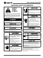
IMPORTANT SAFETY INFORMATION
SAFETY
ALERT
SYMBOL
This symbol is used to call your attention to hazards
or unsafe practices which could result in an injury or
property damage. The signal word, dened below,
indicates the severity of the hazard. The message
after the signal word provides information for pre-
venting or avoiding the hazard.
Immediate hazards which, if not avoided, WILL result
in severe injury or death.
Hazards which, if not avoided, COULD result in
severe injury or death.
Hazards or unsafe practices which, if not avoided,
MAY result in injury or property damage.
• Read and understand all of the
instructions and safety information
in this manual before operating or
servicing this tool.
• Read and understand the instruc-
tion manual supplied with your
cable puller.
Failure to follow instructions and
safety information could result in
severe injury or death.
Wear eye protection when operating
this tool.
Failure to wear eye protection could
result in serious eye injury.
Drop hazard:
Wear foot protection when using this
tool.
Failure to observe this warning could
result in serious injury.
Electric shock hazard:
• Do not expose tool to rain or use in
wet or damp locations.
• Disconnect from power source
before servicing or dismantling the
tool.
• Unplug the tool when not in use.
Failure to observe this warning could
result in severe injury or death.
Make sure the switch is in the OFF position before
connecting this tool to a power source. Accidental
startup could result in serious injury.
Keep hands away from rope and
rollers. Rope can crush a hand.
Failure to observe this warning could
result in severe injury or death.
Do not pull anything other than the pulling rope
through the FG01. Metallic objects such as pulling
grips, clevises and wire rope will damage the rollers.
Failure to observe this precaution may result in
damage to the tool.
Service should be performed by manufacturer-
approved service center only.
Note: Keep all decals clean and legible, and replace
when necessary.

FG01 G-Series Smart Pull
Greenlee / A Textron Company 4455 Boeing Dr. • Rockford, IL 61109-2988 USA • 815-397-7070
4
Principle of Operation
The FG01 G-Series Smart Pull calculates pulling force
by measuring the tension of the rope. The accuracy of
this method is ±2% speed and distance (See table for
he accuracy of the force reading).
The two outer rollers guide the rope into and out of the
device. The prole of the three inner rollers provides
14 degrees of deection. This controlled deection in
the rope path transfers 1/4 of the pulling tension to the
center roller.
The tension on the rope is measured at the center
roller. That roller rides on a compression load cell. As
it is depressed, there is an electronic signal sent to the
display unit, where it is converted to a force to be dis-
played and recorded in either lbs or kg.
The pulling app connects to the device via Bluetooth.
It allows for real-time monitoring of the pull. It can alert
users if the pull force is approaching a pre-determined
threshold. It also allows for seamless documentation,
transferring the data from the unit to the app wirelessly.
From there it can be emailed or posted on social media.
It displays each saved pull in an easy-to-read and easy-
to-understand graph along with the preserved raw data.
The device is battery powered, using Makita 18 V
batteries.
FG01 Load Range (lbs) Tolerance (lbs)
0-1,399 +/- 75
1,400-2,749 +/- 95
2,750-5,599 +/- 140
5,600-10,000 +/- 235
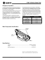
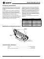
Main Components Identification
Specifications
Capacity ..........................................................................................4536 kg (10,000 lb)
Weight .........................................................................................................16 kg (35 lb)
Maximum Rope Size .................................................................................22 mm (7/8")
Battery
Terminal
Removable
Rollers
Cam
Locking Pin
Bluetooth is a registered trademark of Bluetooth SIG, Inc.
Makita is a registered trademark of the Makita Corporation.

FG01 G-Series Smart Pull
Greenlee / A Textron Company 4455 Boeing Dr. • Rockford, IL 61109-2988 USA • 815-397-7070
5
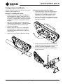
Setup and Installation
Install the G-Series Smart Pull using one of the two
mounting adapters provided.
Mounting to Boom Assembly
1. Refer to the manual supplied with the Ultra Tugger
®
cable puller. After attaching a boom tube to the
boom mount, see steps 2–5 to attach the boom/
gauge mount. Then nish setting up the cable puller.
2. See the illustration. Slide the boom/gauge mount
onto the boom tube. Position it about 4” from the
boom mount as shown.
3. Tighten the set screw.
4. Place the G-Series Smart Pull onto the gauge
mount so that the tabs of the mount go between the
roller side plates as shown.
5. Align the holes and insert the hitch pin.
Mounting to the Ultra Tugger
®
Cable Puller
1. Refer to the manual supplied with the Ultra Tugger
®
cable puller. Set up the cable puller with the chain
mount, pipe sheave adapter, or oor mount.
2. See the illustration. Pull plunger pin to rotate hitch
180 degrees to activate locked position.
3. Position puller/gauge mount between the side
plates of the puller. Align the holes as shown.
4. Insert the hitch pin through the holes.
5. Secure the hitch pin with a hitch pin clip.

FG01 G-Series Smart Pull
Greenlee / A Textron Company 4455 Boeing Dr. • Rockford, IL 61109-2988 USA • 815-397-7070
6
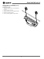
Setup and Installation (cont’d)
Installing the Rope
1. Twist pins counterclockwise and pull out.
2. Remove outer rollers.
3. Lay rope over three inner rollers.
4. Replace outer rollers.
5. Push pins straight in; do not rotate.

FG01 G-Series Smart Pull
Greenlee / A Textron Company 4455 Boeing Dr. • Rockford, IL 61109-2988 USA • 815-397-7070
7
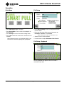
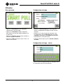
Main Menu
• Press New Pull to begin a new pull.
• Press Saved Pulls to view a list of all saved pulls on
the Smart Pull.
• Press Settings to access the device settings menu.
• Press 180 to rotate the screen 180° if the Smart Pull is
inverted.
Note: Bluetooth name is on the bottom right corner.
Look for this name when pairing with your phone
Pull Setup
• Press Cancel Pulling to exit Pull Setup and return to
the Main Menu.
• Press any of the text elds to enter information for
Pull Name, Foreman, and Location.
*Note: Maximum number of characters is 42
• Select the units of measurement.
• Use the arrows to adjust Maximum Cable Tension.
Pull Setup—Keyboard
Use the keyboard that appears when a text eld is
selected to input data.
Operation

FG01 G-Series Smart Pull
Greenlee / A Textron Company 4455 Boeing Dr. • Rockford, IL 61109-2988 USA • 815-397-7070
8
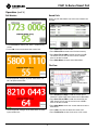
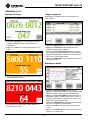
Pull Monitor
• Press End Pull to end the pull. Data is automatically
saved.
• Press 180 at any time to rotate the screen 180°.
• The background changes to yellow when force is at
80% of input tension limit.
• The background changes to red when force exceeds
input tension limit.
Operation (cont’d)
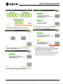
Saved Pulls
Select any le and choose one of the menu buttons on
the right.
• Press Open File to view the le.
• Press Delete File to remove the le from memory.
• Press Save File to USB to export the le to a USB.
The Smart Pull will ask the user to insert a USB if
there is not one inserted.
• Press Main Menu to return to the Main Menu.
File View
• Press Send File to App to send the current le to
Greenlee PullCalc App when connected via Bluetooth.
• Press Save File to USB to send the current le to a
USB. Smart Pull will ask the user to insert a USB if
there is not one inserted.
• Press Main Menu to exit this screen and return to the
Main Menu.
• Press 180 at any time to rotate the screen 180°.
• Press Full Screen to view the chart on a full screen.

FG01 G-Series Smart Pull
Greenlee / A Textron Company 4455 Boeing Dr. • Rockford, IL 61109-2988 USA • 815-397-7070
9
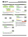
• Run calibration diagnose when this message is
shown. This is to ensure calibration is within range.
• Under the SETTINGS window click DIAGNOSE, to
access to the Diagnose test,
• Follow the instruction and press DIAGNOSE button to
get an status of the current force accuracy
• If the Smart Pull pass the test, you will get a
message just like the one above
• If the Smart Pull fails the test, you will get a
message just like the one above. The recalibration
message can come out while pulling as well if an
error is detected with the calibration.
NOTE: Try to disconnect and connect back the load
cell censor. If this does not work. please contact
customer service, they will take care of you

FG01 G-Series Smart Pull
Greenlee / A Textron Company 4455 Boeing Dr. • Rockford, IL 61109-2988 USA • 815-397-7070
10
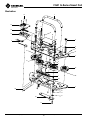
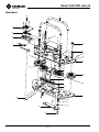
Illustration
19
35
18
34
2
32
33
10
26
22
31
23
1
16
3
6
8
12
27
5
29
4
17
11
30
15
9
14
25
28
24
7
13
20
21

FG01 G-Series Smart Pull
Greenlee / A Textron Company 4455 Boeing Dr. • Rockford, IL 61109-2988 USA • 815-397-7070
11
1 Plate, captive load ................................1
2 Sensors assembly (load and hall) .........1
3 Compressor, center loader ...................1
4 Plate, front (machined) .......................... 1
5 Plate, back (machined) .........................1
6 Through pin, 1 x 0.75 x 0.5 thru ............2
7 Handle weldment .................................. 2
8 SHCS, low prole, 0.375-16 x 1 ...........4
9 BHCS, threadlock, 1/4-20 x 3/4 ...........4
10 SHCS, threadlock, 6-32 x 0.5 ............... 3
11 Cam locking pin, 0.750 ......................... 2
12 Nut, hex (1/2-13NC) ..............................2
13 BHCS, 0.5 x 13, 3.0 long ......................2
14 Set screw, 10-32 x 0.5 .......................... 2
15 Screw, BHCS, 4-40 x 0.25 .................... 2
16 Dowel pin, 0.250 x 2 .............................2
17 Spring, compression ............................. 2
18 Battery terminal assembly ....................1
Key Part No. Description Qty Key Part No. Description Qty
19 SHCS, 6-32 x 1.0 ..................................4
20 Pin, dowel (M4 x 8MM) ......................... 2
21 Spring, compression ............................. 2
22 Screw, SSS, 1/2 x 3/4, 3/8-16 ..............1
23 Nut, hex, 3/8-16 ....................................2
24 Enclosure, electronics ...........................1
25 Screw, FHH, 8-32, 3/8 threadlock ........4
26 Link, assembly total .............................. 1
27 Washer, at, 0.531 ID, 1.250 OD ...........3
28 Decal, warning ......................................1
29 Roller assembly, outside ....................... 2
30 Roller assembly, secondary .................. 2
31 Washer, at, 0.531 ID, 1.500 OD ...........1
32 Wire clamp, nylon .................................1
33 Screw, wire clamp .................................1
34 Battery plate, bottom ............................1
35 Battery plate, top ..................................1
Parts List
Kits
Part No. Description
52077843 Pin and removable roller kit – incudes 1 each of items 11, 14, 17, 20, 21, and 29
52078005 Locked roller and axle kit – includes 1 each of items 6, 12, 13, 27, and 30
52078007 Center roller assembly kit – includes items 3 and 15
52078008 Electronics enclosure kit – includes items 24 and 25
52079814 Battery terminal repair kit – includes item 18
52079813 Sensor repair kit – includes item 2
This device complies with Industry Canada license-exempt RSS
standard(s). Operation is subject to the following two conditions:
(1) this device may not cause interference, and (2) this device must
accept any interference, including interference that may cause
undesired operation of the device.
Le présent appareil est conforme aux CNR d'Industrie Canada
applicables aux appareils radio exempts de licence. L'exploitation
est autorisée aux deux conditions suivantes: (1) l'appareil ne doit pas
produire de brouillage, et (2) l'utilisateur de l'appareil doit accepter
tout brouillage radioélectrique subi, même si le brouillage est
susceptible d'en compromettre le fonctionnement.
Under Industry Canada regulations, this radio transmitter may
only operate using an antenna of a type and maximum (or lesser)
gain approved for the transmitter by Industry Canada. To reduce
potential radio interference to other users, the antenna type and its
gain should be so chosen that the equivalent isotropically radiated
power (e.i.r.p.) is not more than that necessary for successful
communication.
Conformément à la réglementation d'Industrie Canada, le présent
émetteur radio peut fonctionner avec une antenne d'un type et
d'un gain maximal (ou inférieur) approuvé pour l'émetteur par
Industrie Canada. Dans le but de réduire les risques de brouillage
radioélectrique à l'intention des autres utilisateurs, il faut choisir
le type d'antenne et son gain de sorte que la puissance isotrope
rayonnée équivalente (p.i.r.e.) ne dépasse pas l'intensité nécessaire
à l'établissement d'une communication satisfaisante.

4455 Boeing Drive • Rockford, IL 61109-2988 • USA • 815-397-7070
An ISO 9001 Company • Greenlee Textron Inc. is a subsidiary of Textron Inc.
USA Tel: 800-435-0786
Fax: 800-451-2632
Canada Tel: 800-435-0786
Fax: 800-524-2853
International Tel: +1-815-397-7070
Fax: +1-815-397-9247
www.greenlee.com

MANUEL D’INSTRUCTIONS
Veuillez lire et comprendre toutes les
instructions et informations de sécurité de
ce manuel avant d’utiliser cet outil ou d’effectuer
son entretien.
Enregistrez ce produit sur www2.greenlee.com/smartpullregistration
52080178 REV 2 © 2017 Greenlee Textron Inc. 11/17
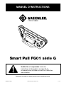
Smart Pull FG01 sérieG

Smart PullFG01 sérieG
Greenlee / A Textron Company 4455 Boeing Dr. • Rockford, IL 61109-2988 É.-U. • 815-397-7070
14
Description
Le Smart PullFG01 sérieG de Greenlee est un treuil de
tirage accessoire destiné à surveiller la force déployée
lorsque le câble est tiré dans un conduit. Le FG01
comprend des dispositions pour le montage du treuil
de tirage Ultra Tugger
®
et la èche Ultra Tugger
®
. An
d’utiliser le FG01 avec d’autres treuils de tirage, il doit
être installé an de supporter la résistance de la corde
roulant sur les cinq rouleaux.
Contient le module transmetteur FCC ID: T9JRN41-3
Cet appareil est conforme à la Partie 15 de la
réglementation FCC. Son fonctionnement est sujet
aux deux conditions suivantes: (1) cet appareil ne
doit pas provoquer de brouillage préjudiciable et (2)
cet appareil doit accepter tout brouillage reçu,
y compris le brouillage susceptible de provoquer
un fonctionnement indésirable.
Sécurité
Lors de l’utilisation et de l’entretien des outils et de
l’équipement de Greenlee, la sécurité est essentielle.
Les instructions de ce manuel et celles qui sont inscrites
sur l’outil fournissent des informations qui permettent
d’éviter les dangers et les manipulations dangereuses
liés à l’utilisation de cet outil. Veiller à respecter toutes
les consignes de sécurité.
Objet de ce manuel
Ce manuel a pour objet de familiariser l’utilisateur avec
les procédures préconisées pour une utilisation et un
entretien sans danger de l’outil Greenlee suivant:
Smart PullFG01 sérieG
Veuillez garder ce manuel à la disposition de tout le
personnel.
Des manuels de rechange peuvent être obtenus
gratuitement sur demande sur www.greenlee.com.
Ne pas éliminer ni jeter ce produit!
Pour obtenir des informations sur le recyclage,
rendez-vous à www.greenlee.com.
Toutes les caractéristiques sont nominales et peuvent changer
lors d’améliorations du produit. Greenlee Textron Inc. décline toute
responsabilité pour les dommages résultant d’un emploi détourné ou
abusif de ses produits.
Ultra Tugger est une marque déposée de Textron Innovations Inc.
CONSERVEZ CE MANUEL
Table des matières
Description .................................................................. 14
Sécurité ....................................................................... 14
Objet de ce manuel ..................................................... 14
Informations de sécurité importantes.......................... 15
Principe de fonctionnement ........................................ 16
Identication des principaux composants .................. 16
Caractéristiques techniques ........................................ 16
Conguration et installation .................................... 17-18
Utilisation ................................................................ 19-21
Illustration .................................................................... 22
Nomenclature des pièces ............................................ 23

Smart PullFG01 sérieG
Greenlee / A Textron Company 4455 Boeing Dr. • Rockford, IL 61109-2988 É.-U. • 815-397-7070
15
INFORMATIONS DE SÉCURITÉ IMPORTANTES
SYMBOLE
D’AVERTISSEMENT
Ce symbole met en garde contre les risques et
les manipulations dangereuses pouvant entraîner
des blessures ou des dégâts matériels. Les mots
indicateurs ci-dessous dénissent la gravité du
danger, et sont suivis d’informations permettant
de prévenir ou d’éviter le danger.
Danger immédiat qui, s’il n’est pas évité,
ENTRAÎNERA des blessures graves ou la mort.
AVERTISSEMENT
Danger qui, s’il n’est pas évité, POURRAIT entraîner
des blessures graves ou la mort.
ATTENTION
Dangers ou manipulations dangereuses qui, s’ils
ne sont pas évités, POURRAIENT entraîner des
blessures ou des dégât matériels.
AVERTISSEMENT
• Veuillez lire et comprendre toutes
les instructions et informations
de sécurité de ce manuel avant
d’utiliser cet outil ou d’effectuer
son entretien.
• Veuillez lire et comprendre le
manuel d’instruction livré avec
votre treuil de tirage.
Le défaut de suivre les directives et les
consignes de sécurité pourrait entraîner
de graves blessures ou la mort.
AVERTISSEMENT
Porter une protection oculaire durant
l’utilisation de cet outil.
L’absence de protection oculaire
peut entraîner des lésions oculaires
graves.
AVERTISSEMENT
Risque de chute:
Porter une protection des pieds
durant l’utilisation de cet outil.
Le non-respect de cette mise en garde
peut entraîner des blessures graves.
AVERTISSEMENT
Danger de décharge électrique:
• Ne pas exposer l’outil à la pluie ni
l’utiliser dans des endroits humides
ou mouillés.
• Débrancher de la prise de
courant avant tout entretien ou
le démontage de l’outil.
• Débrancher l’outil lorsqu’il n’est
pas utilisé.
Le non-respect de cette mise en
garde peut entraîner des blessures
graves ou la mort.
AVERTISSEMENT
S’assurer que l’interrupteur est en position d’ARRÊT
(OFF) avant de raccorder l’outil à une prise de
courant. Un démarrage accidentel pourrait provoquer
des blessures graves.
AVERTISSEMENT
Garder les mains éloignées de la
corde et des rouleaux. La corde peut
écraser une main.
Le non-respect de cette mise en
garde peut entraîner des blessures
graves ou la mort.
ATTENTION
Ne rien tirer d’autre que la corde de tirage avec le
FG01. Les objets métalliques comme les tire-câbles,
les manilles et les câbles d’acier endommageront les
rouleaux.
Le non-respect de cette consigne peut entraîner des
dommages à l’outil.
Le service doit être uniquement effectué par un
centre de réparations approuvé par le fabricant.
Remarque: conserver toutes les décalcomanies dans
un état propre et lisible et les remplacer au besoin.

Smart PullFG01 sérieG
Greenlee / A Textron Company 4455 Boeing Dr. • Rockford, IL 61109-2988 É.-U. • 815-397-7070
16
Principe de fonctionnement
Le Smart PullFG01 sérieG calcule la force de tirage en
mesurant la tension de la corde. La précision de cette
méthode est la vitesse et la distance ±2% de la force
de tirage.
Les deux rouleaux externes guident la corde dans et
hors du dispositif. Le prol des trois rouleaux internes
procure une déexion de 14degrés. Cette déexion
contrôlée dans le chemin de la corde transfère 1/4de la
tension de tirage vers le rouleau du centre.
La tension de la corde est mesurée au rouleau du
centre. Ce rouleau roule sur un capteur de compression.
Lorsqu’il est enfoncé, un signal électronique est envoyé
à l’afcheur, où il est converti en une force qui sera
afchée et enregistrée, soit en lb ou en kg.
L’application de tirage se connecte au dispositif par
Bluetooth. Cela permet une surveillance du tirage en
temps réel. Il peut avertir les utilisateurs si la force de
tirage approche d’un seuil préalablement déterminé. Il
permet aussi une documentation continue, transférant
les données de l’appareil à l’application sans l. Il
peut ensuite être envoyé par courriel ou afché sur un
média social. Il afche chaque tirage enregistré dans
un graphique facile à lire et à comprendre, ainsi que les
données brutes conservées.
Le dispositif est alimenté par pile au moyen de piles
Makita 18V.
FG01 Plage de charge (lbs) Tolerance (lbs)
0-1,399 +/- 75
1,400-2,749 +/- 95
2,750-5,599 +/- 140
5,600-10,000 +/- 235
Identification des éléments principaux
Caractéristiques techniques
Capacité .........................................................................................4536kg (10000lb)
Poids...........................................................................................................16kg (35lb)
Grosseur maximale de la corde ............................................................. 22mm (7/8po)
Borne
de pile
Rouleaux
amovibles
Goupille de
verrouillage par came

Smart PullFG01 sérieG
Greenlee / A Textron Company 4455 Boeing Dr. • Rockford, IL 61109-2988 É.-U. • 815-397-7070
17
Configuration et installation
Installer le Smart Pull sérieG en utilisant l’un des deux
adaptateurs de montage fourni.
Montage à l’assemblage de la flèche
1. Veuillez consulter le manuel qui accompagne le
treuil de tirage Ultra Tugger
®
. Après avoir xé le
tube de èche au montage de la èche, consulter
les étapes2 à 5 pour xer le montage de la èche/
jauge. Ensuite, terminer la conguration du treuil
de tirage.
2. Consulter l’illustration. Glisser le montage de la
èche/jauge au tube de èche. Le placer à environ
4po du montage de la èche comme illustré.
3. Serrer la vis de réglage.
4. Mettre le Smart Pull sérieG sur le montage de
la jauge an que les languettes du montage se
trouvent entre les plaques latérales du rouleau
comme illustré.
5. Aligner les trous et insérer la goupille d’attelage.
Montage au treuil de tirage Ultra Tugger
®
1. Veuillez consulter le manuel qui accompagne le
treuil de tirage Ultra Tugger
®
. Installer le treuil
de tirage avec le montage de chaîne, le galet
adaptateur de tuyau ou le montage au sol.
2. Consulter l’illustration. Tirer la goupille du piston
pour tourner l’attelage à 180degrés an d’activer
la position verrouillée.
3. Placer le montage treuil/jauge entre les plaques
latérales du treuil. Aligner les trous comme illustré.
4. Insérer la goupille d’attelage dans les trous.
5. Fixer la goupille d’attelage avec une agrafe pour
goupille d’attelage.

Smart PullFG01 sérieG
Greenlee / A Textron Company 4455 Boeing Dr. • Rockford, IL 61109-2988 É.-U. • 815-397-7070
18
Configuration et installation (suite)
Installation de la corde
1. Tourner les goupilles dans le sens antihoraire et
les sortir.
2. Retirer les rouleaux externes.
3. Disposer la corde sur les trois rouleaux internes.
4. Replacer les rouleaux externes.
5. Pousser à fond les goupilles; ne pas tourner.

Smart PullFG01 sérieG
Greenlee / A Textron Company 4455 Boeing Dr. • Rockford, IL 61109-2988 É.-U. • 815-397-7070
19
Menu principal
• Appuyer sur New Pull (nouveau tirage) pour
commencer un nouveau tirage.
• Appuyer sur Saved Pulls (tirages enregistrés)
pour afcher une liste des tirages enregistrés sur
le Smart Pull.
• Appuyer sur Settings (réglages) pour accéder au
menu de réglage du dispositif.
• Appuyer sur 180 pour tourner l’écran à 180° si le
Smart Pull est inversé.
Configuration du tirage
• Appuyer sur Cancel Pulling (annuler tirage) pour
quitter la conguration du tirage et revenir au menu
principal.
• Appuyer sur l’un des champs de texte pour saisir
les informations dont le Pull Name (nom du tirage),
Foreman (contremaître) et Location (emplacement).
• Sélectionner les unités de mesure.
• Utiliser les èches pour ajuster la tension maximale
du câble.
Configuration du tirage – clavier
Utiliser le clavier qui apparaît lorsqu’un champ de texte
est sélectionné pour saisir des données.
Utilisation

Smart PullFG01 sérieG
Greenlee / A Textron Company 4455 Boeing Dr. • Rockford, IL 61109-2988 É.-U. • 815-397-7070
20
Moniteur de tirage
• Appuyer sur End Pull (n de tirage) pour terminer
le tirage. Les données sont automatiquement
enregistrées.
• Appuyer sur180 en tout temps pour tourner l’écran
à 180°.
• Le fond devient jaune lorsque la force est à 80% de
la limite de tension saisie.
• Le fond devient rouge lorsque la force dépasse la
limite de tension saisie.
Utilisation (suite)
Tirages enregistrés
Sélectionner un cher et choisir un des boutons du
menu à droite.
• Appuyer sur Open File (ouvrir chier) pour voir le chier.
• Appuyer sur Delete File (supprimer chier) pour
supprimer le chier de la mémoire.
• Appuyer sur Save File to USB (enregistrer le chier
sur clé USB) pour exporter le chier à une clé USB. Le
Smart Pull demandera à l’utilisateur d’insérer une clé
USB si elle n’est pas déjà insérée.
• Appuyer sur Main Menu (menu principal) pour revenir
au menu principal.
Affichage de fichier
• Appuyer sur Send File to App (envoyer chier à
application) pour envoyer le chier actuel à l’application
Greenlee PullCalc, lorsque connecté par Bluetooth.
• Appuyer sur Save File to USB (enregistrer chier sur
USB) pour envoyer le chier actuel à une clé USB. Le
Smart Pull demandera à l’utilisateur d’insérer une clé
USB si elle n’est pas déjà insérée.
• Appuyer sur Main Menu (menu principal) pour quitter
cet écran et revenir au menu principal.
• Appuyer sur 180 en tout temps pour tourner l’écran
à 180°.
• Appuyer sur Full Screen (plein écran) pour afcher le
tableau sur un plein écran.
A página está carregando...
A página está carregando...
A página está carregando...
A página está carregando...
-
 1
1
-
 2
2
-
 3
3
-
 4
4
-
 5
5
-
 6
6
-
 7
7
-
 8
8
-
 9
9
-
 10
10
-
 11
11
-
 12
12
-
 13
13
-
 14
14
-
 15
15
-
 16
16
-
 17
17
-
 18
18
-
 19
19
-
 20
20
-
 21
21
-
 22
22
-
 23
23
-
 24
24


Greenlee FG01 G-Series Smart Pull Manual do usuário
- Tipo
- Manual do usuário
em outras línguas
Artigos relacionados
-
Greenlee Long Reach Chain Saws - Portuguese Manual do usuário
-
-
GREENLINE 200B-G Manual do usuário
-
-
-
-
-

