StetSom BRAVO HQ 800.4 Manual do usuário
- Categoria
- Amplificadores de áudio para carro
- Tipo
- Manual do usuário

USER MANUAL
MANUAL DO USUÁRIO • MANUAL DE USUARIO • MANUALE UTENTE
800.4

2
Introduction
Thank you so much for choosing a Stetsom product! The chosen amplifier has been
developed with the most advanced technology for who are looking for high performance
audio systems with one or more speakers.
If you have questions , contact the store where the purchase or installation was
made. For more information please contact our Customer Service:
+55 18 2104 9412.
Before isntalling
Please read this manual carefully.
• All product connections must be made with the product turned OFF.
• A fuse must be installed between the amplifier and the battery is required to protect
against overcharging. The fuse need be installed as close to the battery as possible. Check
the proper fuse for the amplifier according to its consumption.
• Use gauges recommended in this manual to avoid the overheating of the cables to obtain
maximum power.
• Keep the cables as short as possible to increase sound fidelity and avoid potential power
losses.
• Route the installation cables as far away as possible from the original vehicle wiring as
it may cause interference and noise in your audio system.
• Perform the installation in a firm, ventilated and dry place.
• Installation must be done by a qualified professional.
EN-US

3
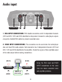
1. RCA INPUT CONNECTIONS: RCA double connections with 4 independent channels
(CH1 and CH2 / CH3 and CH4) identified on the product. Connect to radio/player outputs
via quality shielded RCA cables to prevent unwanted noise.
2. HIGH INPUT CONNECTIONS: This connection can be used when the radio/player
does not have RCA audio outputs. Each connector has 2 independent channels (CH1 and
CH2 / CH3 and CH4) identified in the amplifier. Check the signals of the amplified output
of the radio/player before making connections.
Audio input
VENTILATION VENTILATION
1 12 2
REMOTE IN
(GREEN WIRE)
X CHANNEL
Y CHANNEL
(GRAY)
(BLUE)
Using the RCA input and HIGH
INPUT connections at the same
time can cause unwanted noise
and amplifier problems.
(GRAY)
(BLUE)

4
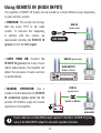
• REDECAN: This system has timings
that can cause PUFF in the audio
system. To minimize this happening
in vehicles with this system, we
recommend installing the REMOTE IN
(green) wire to the ACC signal.
• AUTO TURN ON: Connect the
REMOTE IN (green) wire to any of your
radio’s audio outputs. The amplifier will
detect the presence of audio and turn
on automatically.
• MANUAL OPERATION: Use a
switch or button between the REMOTE
IN connection (green wire) and the
positive 12V battery supply for manual
operation of the amplifier.
Using REMOTE IN (HIGH INPUT)
The amplifier’s REMOTE IN feature can be turned on in three dierent ways, depending
on your vehicle’s system.
REM IN
(green wire)
Wire Harness
HIGH INPUT
Wire Harness
HIGH INPUT
Wire Harness
HIGH INPUT
REM IN
(green wire)
REM IN (green wire)
ACC SIGNAL
STETSOM
HIGH OUTPUT
(Radio / Player)
Switch or Button
If your radio has a remote (REM) output, connect it directly to the REM IN (green
wire) of the HIGH INPUT output for automatic amplifier activation.

5
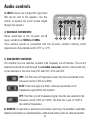
5. CROSSOVER SWITCHES:
The amplifier has two selection switches with frequency cut-o function. The cut-o
adjustment should be made through the variable crossover controls. Each switch acts
on two channels at the same time (CH1 and CH2 / CH3 and CH4).
3. LEVEL: Allows you to adjust the signal level
that will be sent to the speakers. Use this
control to equalize the music volume played
through the speakers.
4. VARIABLE CROSSOVER:
Allows adjustment of the crossover cut-o
range, variable from 50Hz to 2.3KHz.
These controls operate in conjunction with the crossover switches, allowing cuto
adjustment on the selected switch (H.P.F. or L.P.F.).
6. COOLER: Its operation is automatic and variable, optimizing the amplifier's ventilation.
Make the installation in a ventilated place, without obstruction in the air inlets and outlets.
Audio controls
HPF: This filter cuts o frequencies lower than the one selected in the
crossover control (50Hz to 2.3KHz).
FLAT: It does not apply any filters, allowing reproduction of all
frequencies supported by the amplifier.
LPF: This filter cuts o frequencies higher than the one selected in the
crossover control (50Hz to 2.3KHz). The filter has a gain of +12dB at
the selected frequencies.
3 5 564 34

6
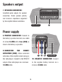
Power supply
8. POSITIVE CONNECTOR: Connect to
the battery's positive terminal via a cable
of at least 6 AWG with a fuse (40A) as
close to the battery as possible.
9. CONNECTOR FOR REMOTE
ACTIVATION (REM): Allows automatic
activation of the amplifier when turning on
the radio/player. Connect to the REMOTE
output of the radio/player via a minimum
18 AWG cable.
10. NEGATIVE CONNECTOR: Connect
to the negative battery terminal via a
minimum 6 AWG cable.
Speakers output
7. SPEAKERS CONNECTOR:
Amplified audio outputs for speaker
connection. Check speaker polarity
and minimum impedance supported
by the amplifier before installation.
7
VENTILATION
7 8 97 8 9 VENTILATION

7
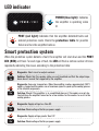
Smart protection system
When the protection system detects a fault, the amplifier will shut down and the PROT
LED (RED) will flash. For each type of fault, the LED will flash a certain number of times
repeatedly indicating the cause, according to the protection table:
LED indicator
Diagnostic: Short circuit or output overload.
Diagnostic: Supply voltage less than 9V.
Solution: Check that the speaker cables are well insulated and that the output impe-
dance doesn’t exceed that supported by the amplifier.
Solution: Check voltage of battery or power supply.
Solution: Check if the amplifier is in a ventilated place or if the coolers are not obs-
tructed. Keep the amplifier turned on for a few minutes for the coolers to assist in the
cooling process.
Solution: Check voltage of battery or power supply.
Diagnostic: Excessive temperature. When the amplifier reaches approximately 194°F,
audio is stopped and the coolers run at maximum speed to speed up the cooling process
of the internal components.
Diagnostic: Supply voltage greater than 17V.
blink
1x
blink
3x
blink
4x
blink
2x
Hq800.4 @ 2 OHMs
POWER
/ PROT
CAR AUDIO
AMPLIFIER
POWER (blue light): Indicates
the amplifier is operating when
lit.
PROT (red light): Indicates that the amplifier detected faults and
entered protection mode. Check the protection table for possible
failure and turn the amplifier back on.

8
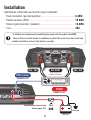
• Installation must be done only by qualified professionals with the product turned OFF.
• The use of fuse or circuit breaker is mandatory to protect the system from short circuit and
overload. Install them as close to the battery as possible.
Baery
Ground
Installation
Specification of the cables and fuse for proper installation:
• Power connectors (positive/negative) ....................................................................
• Remote connecto (REM) ............................................................................................
• Output signal connectors (speakers) .....................................................................
• Fuse ................................................................................................................................
6 AWG
18 AWG
13 AWG
40A
Radio / Player
RCA INPUT
CH4 / CH3
STETSOM
CH2 / CH1
POWER
6 AWG cables
18 AWG cable
Install the fuse closest to the
battery (max. 12”).
Fuse
40A
REM (remote)

9
SPEAKERS
13 AWG cables
Check the minimum impedance
CH3CH4 CH1CH2
REMOTE IN (GREEN WIRE)
BLUE WIRE
GRAY WIRE
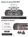
HIGH INPUT diagram
Use example:
4 x SPEAKERS 2 OHMS
2 x SPEAKERS 2 OHMS +
1 x SUBWOOFER 4 OHMS (BRIDGE)
2 x SUBWOOFER 4 OHMS (BRIDGE)
Use the RCA and HIGH INPUT connections at the same time can cause unwanted
noise and amplifier problems.
Speakers installation
STEREO
2 OHMS min. BRIDGE
4 OHMS min.

10
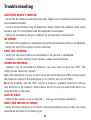
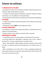
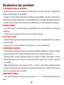
Troubleshooting
AMPLIFIER DOESN’T TURN ON:
• Verify that the cables are connected correctly. Make sure all connections have electrical
and mechanical contact.
• Fuses or circuit breakers may be defective or blown. Check the condition of the circuit
breakers and if it is compatible with the equipment consumption.
• Verify that the battery charge is sucient for the operation of the product
NO SOUND:
• The cables of the speakers or connections may not be connected correctly or are defective.
• Verify that the LEVEL control is not at a minimum.
PROT LED FLASHING:
• Verify that the product vents are not blocked or the product is overheated.
• Speakers or cables shorted, check speakers, cables and connections.
SOUND DISTORTIONS:
• Speakers may be overloaded or defective, turn down and re-adjust the LEVEL. This
setting can be adjusted as follows:
a) On the radio/player, put any musical signal and set the volume to 80% of maximum (if
the maximum volume of the radio/player is 45 (100%), set it to 36 (80%).
b) On the amplifier, with the LEVEL control at minimum, gradually increase it until you
hear distortion in the speakers. Slowly return the LEVEL until you notice that there is no
more distortion in the audio.
LACK OF BASS:
• Cables of the speakers may be reversed and (out-of-phase speakers).
NOISE AND FAILURE IN SOUND:
• Verify that the installation is not close to the original vehicle wiring as they may cause
interference and noise in the audio signal.

11
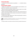
• Make a separate power connection to the sound system. Use a fuse/ circuit breaker as
close to the battery as possible for protection.
• Make a good grounding of the amplifier. To do this, remove the paint from the vehicle
chassis at the desired point. Screw the wire using a ground terminal. To protect from
oxidation, isolate with paint.
• Do not loop the ground. Avoid using multiple grounds. If possible, use a star connection,
in which all the grounds run from a single point.
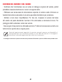
Any updates made in this manual will be available for costormers to consult without any
charge on the brand’s site.
It is recommended that the updated manual be consulted whenever needed.

12
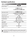
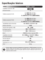
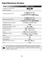
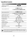
MODEL HQ800.4 - 2 OHMS
Techinical specications
Minimum output impedance:
Number of channels:
Power output @ 14.4V:
Power output @ 12.6V:
Minimum input sensitivity:
Signal to noise ratio:
Frequency response (-3dB):
Crossover Low Pass:
Crossover High Pass:
Boost:
Input impedance:
Supply voltage:
Musical consumption:
BASS consumption:
Dimensions (H x W x L):
Weight:
4
RCA: 250mV / HIGH INPUT: 1.5V
>80dB
5Hz ~ 22KHz
50Hz ~ 2,3K (Variable)
50Hz ~ 2,3K (Variable)
+12dB (with switch in L.P.F)
RCA: 18KOhms / HIGH INPUT: 1KOhms
9V ~ 17V DC
43A
86A
2.3” x 6.6” x 9.3”
3.3 lb
2 OHMs
4 x 250W RMS @ 2 Ohms
4 x 170W RMS @ 4 Ohms
2 x 500W RMS @ 4 Ohms (BRIDGE MODE)
4 x 200W RMS @ 2 Ohms
4 x 130W RMS @ 4 Ohms
2 x 400W RMS @ 4 Ohms (BRIDGE MODE)
The data measured are based on STETSOM laboratory equipment. Test reference in frequency from 60hz to
1Khz with THD + N at ≤1% in impedances as indicated in each measurement. The electronic components
and the manufacturing process may present manufacturing variations, thus leading to a variation in the
measurements made.

13
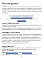
Warranty Term
STETSOM, through its network of Authorized Technical Assistance Providers, guarantees technical
assistance to the purchaser of their products. The repairs of any defects duly established as being of
the manufacturer will be done without cost for replacement components or parts and repair labor.
The repairs will be done by the Authorized Technical Assistance Provider specially designated by
STETSOM.
CONSULT THE LIST OF AUTHORIZED TECHNICAL ASSISTANCE PROVIDERS ON OUR WEBSITE:
www.stetsom.com.br/en/assistencias-tecnica
If you do not locate technical assistance in your city, please contact us at:
BR +55 18 2104-9412
WARRANTY CONDITIONS:
Our warranty is 1 (one) year against manufacturing defects. Its validity starts on the date of the Sale
to the FINAL Consumer.
To make use of the benefits of this warranty, you must present one of the following documents: the
Final Consumer’s SALE NOTE or this completed CERTIFICATE.
CASES THAT VOID THE WARRANTY:
1. 1 year after the issuance of the invoice of sale to the consumer or 1 year of completing certificate
of warranty (dated and stamped by the retailer or installer) or 1 year from date of manufacture.
2. Violation of seals, alteration or removal of the product’s serial or lot number.
3. If the product suers misuse, careless accidents involving: Water, Fire or Fall, or is installed in
conditions contrary to the guidelines contained in the installation manual that accompanies the
product.
4. Damages and changes in the circuit or adaptation of non-original parts.
5. If you use installation techniques contrary to those given in the manual.
QUESTIONS AND ADVICE:
STETSOM oers Customer Services to answer questions and give advice about their products and
services. Please contact us through the channels:
Phone: BR +55 18 2104-9412
E-mail: [email protected] — Site: www.stetsom.com

14
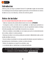
Introdução
Muito obrigado por escolher um produto Stetsom! O amplificador escolhido foi
desenvolvido com a mais avançada tecnologia para quem busca alto desempenho em
sistemas de áudio interno e externo com um ou mais alto-falantes.
Em caso de dúvidas, informe-se com a loja, onde foi realizada a instalação ou
entre em contato com o nosso SAC: 018 2104 9412.
PT-BR
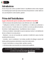
Antes de instalar
Leia atentamente este manual antes de usar o produto.
• Todas as conexões do produto devem ser feitas com o mesmo DESLIGADO.
• É obrigatória a instalação de um fusível entre o amplificador e a bateria para proteção
em caso de sobrecarga. O fusível deve ser instalado o mais próximo possível da bateria.
• Verifique o fusível adequado para o amplificador de acordo com o seu consumo.
• Utilize bitolas recomendadas neste manual para evitar sobreaquecimento dos cabos e
obter o máximo de potência.
• Mantenha os cabos o mais curto possível a fim de aumentar a fidelidade sonora e evitar
possíveis perdas de potência.
• Distribua os cabos da instalação o mais longe possível da fiação original do veículo, já
que ela pode gerar interferência e ruído em seu sistema de áudio.
• Efetue a instalação em local firme, arejado e seco.
• A instalação deve ser feita por um profissional qualificado.

15
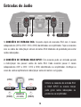
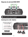
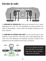
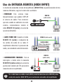
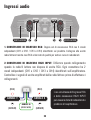
1. CONEXÕES DE ENTRADA RCA: Conjunto duplo de conexões RCA com 4 canais
independentes (CH1 e CH2 / CH3 e CH4) identificados no amplificador. Faça as conexões
com as saídas do rádio/player através de cabos RCA blindados de qualidade para evitar
ruídos indesejados.
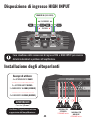
2. CONEXÕES DE ENTRADA HIGH INPUT: Esta conexão pode ser utilizada quando
o rádio/player não possuir saídas de áudio RCA. Cada conector possui 2 canais
independentes (CH1 e CH2 / CH3 e CH4) identificados no amplificador. Verifique os
sinais da saída amplificada do rádio/player antes de realizar as ligações.
Entradas de áudio
VENTILAÇÃOVENTILAÇÃO VENTILAÇÃO
1 12 2
REMOTE IN
(FIO VERDE)
CANAL X
CANAL Y
(CINZA) (CINZA)
(AZUL) (AZUL)
Utilizar as conexões de entrada RCA
e HIGH INPUT ao mesmo tempo
pode gerar ruídos indesejados ou
problemas no amplificador.

16
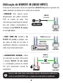
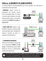
• REDECAN: Este sistema possui
temporizações que podem ocasionar
PUFF no sistema de áudio. Para
minimizar que isso aconteça em veículos
com este sistema, recomendamos a
instalação do fio REMOTE IN (verde)
ao sinal pós-chave.
• AUTO TURN ON: Conecte o fio
REMOTE IN (verde) a qualquer uma
das saídas de áudio do seu rádio. O
amplificador detectará a presença do
áudio e ligará automaticamente.
• ACIONAMENTO MANUAL: Utilize
um interruptor ou chave TicTac entre
a conexão REMOTE IN (fio verde)
e a alimentação positiva da bateria
12V para acionamento manual do
amplificador.
Utilização do REMOTE IN (HIGH INPUT)
O recurso de acionamento remoto do amplificador (REMOTE IN) pode ser ligado de três
modos diferentes, de acordo com o sistema do seu veículo:
REM IN
(fio verde)
Chicote
HIGH INPUT
Chicote
HIGH INPUT
Chicote
HIGH INPUT
REM IN
(fio verde)
REM IN (fio verde)
PÓS-CHAVE
STETSOM
SAÍDA HIGH
(Rádio / Player)
Chave ou Botão
Caso seu rádio tenha saída remoto (REM), conecte-a diretamente ao REM IN (fio
verde) da saída HIGH INPUT para o acionamento automático do amplificador.

17
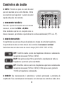
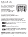
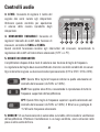
5. CHAVE CROSSOVER:
O amplificador possui duas chaves de seleção com função de corte de frequências.
O ajuste de corte deve ser feito através dos controles de crossover variável.
Cada chave atua em dois canais ao mesmo tempo (CH1 e CH2 / CH3 e CH4).
3. LEVEL: Permite o ajuste do nível de sinal
que será enviado para os alto-falantes. Utilize
esse controle para equalizar o volume musical
reproduzido pelos alto-falantes.
4. CROSSOVER VARIÁVEL:
Permite o ajuste da faixa de corte do recurso
crossover, variável de 50Hz a 2,3KHz.
Estes controles operam em conjunto com as
6. COOLER: Seu funcionamento é automático e variável, optimizando a ventilação do
amplificador. Faça a instalação em local arejado, sem obstrução nas entradas e saídas de ar.
Controles de áudio
HPF: Este filtro realiza o corte das frequências inferiores à selecionada
no controle crossover (50Hz a 2,3KHz).
FLAT: Não aplica nenhum filtro, permitindo a reprodução de todas as
frequências suportadas pelo amplificador.
LPF: Este filtro realiza o corte das frequências superiores à selecionada
no controle crossover (50Hz a 2,3KHz). O filtro possuo um ganho de
+12dB nas frequências selecionadas.
3 5 564 34
chaves crossover, permitindo o ajuste de corte na chave selecionada (H.P.F. ou L.P.F).

18
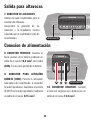
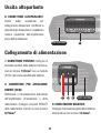
Conexão de alimentação
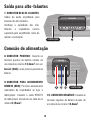
8. CONECTOR POSITIVO: Conecte ao
terminal positivo da bateria através de
um cabo de no mínimo 13,3mm² com um
fusível (40A) o mais próximo possível da
bateria.
9. CONECTOR PARA ACIONAMENTO
REMOTO (REM): Permite o acionamento
automático do amplificador ao ligar o
rádio/player. Conecte à saída REMOTE
do rádio/player através de um cabo de no
mínimo 0,75mm².
10. CONECTOR NEGATIVO: Conecte ao
terminal negativo da bateria através de
um cabo de no mínimo 13,3mm².
Saída para alto-falantes
7. CONECTOR DE ALTO-FALANTES:
Saídas do áudio amplificado para
conexão dos alto-falantes.
Verifique a polaridade dos alto-
falantes e impedância miníma
suportada pelo amplificador antes de
realizar a instalação.
7
VENTILAÇÃO
VENTILAÇÃO
7 8 98 9 10

19
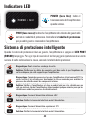
Diagnóstico: Curto circuito ou sobrecarga na saída.
Diagnóstico: Tensão de alimentação inferior a 9V.
Solução: Verifique se os cabos do alto falante estão bem isolados e se a impedância na
saída não está abaixo da suportada pelo amplificador.
Solução: Verifique a tensão da bateria ou fonte de alimentação.
Solução: Verifique se o amplificador está em local ventilado ou se os coolers não estão
obstruídos. Mantenha o amplificador ligado por alguns minutos para que os coolers
auxiliem no processo de resfriamento.
Solução: Verifique a tensão da bateria ou fonte de alimentação.
Diagnóstico: Temperatura excessiva. Quando o amplificador atinge aproximadamente
90°C, o áudio é interrompido e os coolers trabalham em rotação máxima para acelerar
o processo de resfriamento dos componentes internos.
Diagnóstico: Tensão de alimentação superior a 17V.
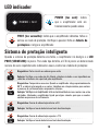
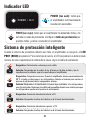
Sistema de proteção inteligente
Quando o sistema de proteção detecta uma falha, o amplificador irá desligar e o LED
PROT (VERMELHO) irá piscar. Para cada tipo de falha, o LED irá piscar um determinado
número de vezes repetidamente indicando a causa, conforme a tabela de proteções:
Pisca
1x
Pisca
3x
Pisca
4x
Pisca
2x
Hq800.4 @ 2 OHMs
POWER
/ PROT
CAR AUDIO
AMPLIFIER
LED indicador
POWER (luz azul): Indica
que o amplificador está em
funcionamento quando aceso.
PROT (luz vermelha): Indica que o amplificador detectou falhas e
entrou no modo de proteção. Verifique a possível falha na tabela de
proteções e religue o amplificador.

20
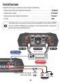
• A instalação deve ser feita somente por profissionais qualificados e com o produto DESLIGADO.
• O uso de fusível é obrigatório para proteger o sistema de curto circuito e sobrecarga. Instale o
mais próximo possível da bateria.
Bateria
Terra
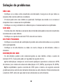
Instalação
Especificações de fusível e bitolas recomendadas para a instalação:
• Cabos para alimentação (positivo/negativo) ........................................................
• Cabo para acionamento remoto (REM) ..................................................................
• Cabos para saída de áudio (alto-falantes) ............................................................
• Fusível ............................................................................................................................
13,3mm²
0,75mm²
2,5mm²
40A
Rádio / Player
ENTRADA RCACH4 / CH3
STETSOM
CH2 / CH1
Cabos de 13,3mm
Cabo de 0,75mm
Instale o fusível o mais próximo
da bateria (máx. 30cm).
Fusível
40A
ALIMENTAÇÃO
REM (remote)
A página está carregando...
A página está carregando...
A página está carregando...
A página está carregando...
A página está carregando...
A página está carregando...
A página está carregando...
A página está carregando...
A página está carregando...
A página está carregando...
A página está carregando...
A página está carregando...
A página está carregando...
A página está carregando...
A página está carregando...
A página está carregando...
A página está carregando...
A página está carregando...
A página está carregando...
A página está carregando...
A página está carregando...
A página está carregando...
A página está carregando...
A página está carregando...
A página está carregando...
A página está carregando...
A página está carregando...
A página está carregando...
A página está carregando...
A página está carregando...
A página está carregando...
A página está carregando...
-
 1
1
-
 2
2
-
 3
3
-
 4
4
-
 5
5
-
 6
6
-
 7
7
-
 8
8
-
 9
9
-
 10
10
-
 11
11
-
 12
12
-
 13
13
-
 14
14
-
 15
15
-
 16
16
-
 17
17
-
 18
18
-
 19
19
-
 20
20
-
 21
21
-
 22
22
-
 23
23
-
 24
24
-
 25
25
-
 26
26
-
 27
27
-
 28
28
-
 29
29
-
 30
30
-
 31
31
-
 32
32
-
 33
33
-
 34
34
-
 35
35
-
 36
36
-
 37
37
-
 38
38
-
 39
39
-
 40
40
-
 41
41
-
 42
42
-
 43
43
-
 44
44
-
 45
45
-
 46
46
-
 47
47
-
 48
48
-
 49
49
-
 50
50
-
 51
51
-
 52
52


StetSom BRAVO HQ 800.4 Manual do usuário
- Categoria
- Amplificadores de áudio para carro
- Tipo
- Manual do usuário
em outras línguas
- español: StetSom BRAVO HQ 800.4 Manual de usuario
- italiano: StetSom BRAVO HQ 800.4 Manuale utente
- English: StetSom BRAVO HQ 800.4 User manual
Artigos relacionados
-
StetSom BRAVO HQ400.4 Manual do proprietário
-
-
-
-
-
-
-