
Industrial Heat-Tracing
Installation and Maintenance
Manual For Self-Regulating and
Power-Limiting Heating Cable Systems
nVent.com

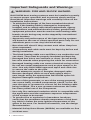
Important Safeguards and Warnings
WARNING: FIRE AND SHOCK HAZARD.
RAYCHEM heat-tracing systems must be installed correctly
to ensure proper operation and to prevent shock and fire.
Read these important warnings and carefully follow all the
installation instructions.
• To minimize the danger of fire from sustained electrical
arcing if the heating cable is damaged or improperly
installed, and to comply with nVent requirements, agency
certifications, and national electrical codes, ground-fault
equipment protection must be used on each heating cable
branch circuit. Arcing may not be stopped by conventional
circuit breakers.
• Approvals and performance of the heat-tracing systems
are based on the use of nVent specified parts only. Do not
substitute parts or use vinyl electrical tape.
• Bus wires will short if they contact each other. Keep bus
wires separated.
• Components and cable ends must be kept dry before and
during installation.
• The black heating cable core and fibers are conductive and
can short. They must be properly insulated and kept dry.
• Damaged bus wires can overheat or short. Do not break
bus wire strands when preparing the cable for connection.
• Damaged heating cable can cause electrical arcing or fire.
Do not use metal attachments such as pipe straps or tie
wire. Use only RAYCHEM approved tapes and cable ties
to secure the cable to the pipe.
• Do not attempt to repair or energize damaged cable.
Remove damaged cable at once and replace with a
new length using the appropriate RAYCHEM splice kit.
Replace damaged components.
• Re-use of the grommets, or use of the wrong grommet,
can cause leaks, cracked components, shock, or fire. Be
sure the type of grommet is correct for the heating cable
being installed. Use a new grommet whenever the cable
has been pulled out of the component.
• Use only fire-resistant insulation which is compatible with
the application and the maximum exposure temperature
of the system to be traced.
• To prevent fire or explosion in hazardous locations,
verify that the maximum sheath temperature of the heat-
ing cable is below the auto-ignition temperature of the
gases in the area. For further information, see the design
documentation.
• Material Safety Data Sheets (MSDSs) are available on-line
at nVent.com.
ii | nVent.com

Table of Contents
1
General Information 5
1.1 Use of the Manual 5
1.2 Safety Guidelines 5
1.3 Electrical Codes 5
1.4 Warranty and Approvals 6
1.5 General Installation Notes 6
2
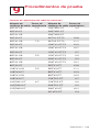
Heating Cable Selection 7
3
Heating Cable Installation 8
3.1 Heating Cable Storage 8
3.2 Pre-Installation Checks 8
3.3 Installation 9
4
Heating Cable Components 20
4.1 General Component Information 20
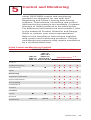
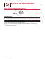
5
Control and Monitoring 23
6
Thermal Insulation 25
6.1 Pre-Insulation Checks 25
6.2 Insulation Installation Hints 25
6.3 Marking 25
6.4 Post-Insulation Testing 25
7
Power Supply and Electrical Protection 26
7.1 Voltage Rating 26
7.2 Electrical Loading 26
7.3 Ground-Fault Protection 26
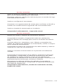
8
Commissioning and Preventive Maintenance 27
8.1 Tests 27
8.2 Preventive Maintenance 28
nVent.com | iii

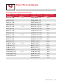
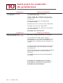
9
Test Procedures 29
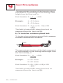
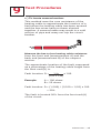
9.1 Visual Inspection 29
9.2 Insulation Resistance (Megger) Test 29
9.3 Power Check 32
9.4 Fault Location Tests 33
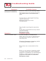
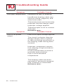
10
Troubleshooting Guide 38
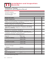
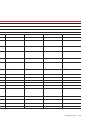
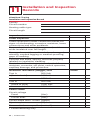
11
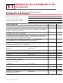
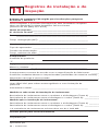
Installation and Inspection Records 40
iv | nVent.com

1
General Information
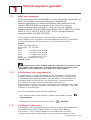
1.1 Use of the Manual
This installation and maintenance manual is for
nVent RAYCHEM Self-Regulating and Power-
Limiting heat-tracing systems on thermally
insulated pipes and vessels only. This includes
RAYCHEM BTV, HBTV, QTVR, HQTV, XTV, HXTV,
KTV, VPL heating cables and the appropriate
RAYCHEM components.
For information regarding other applications,
design assistance or technical support, contact
your nVent representative or nVent directly.
nVent
7433 Harwin Drive
Houston, TX 77036 USA
Tel: +1.800.545.6258
Tel: +1.650.216.1526
Fax: +1.800.527.5703
Fax: +1.650.474.7711
nVent.com
Important: For the nVent warranty and agency
approvals to apply, the instructions that are
included in this manual and product packages
must be followed.
1.2 Safety Guidelines
The safety and reliability of any heat-tracing
system depends on proper design, installation
and maintenance. Incorrect handling, installa-
tion, or maintenance of any of the system com-
ponents can cause underheating or overheating
of the pipe or damage to the heating cable
system and may result in system failure, electric
shock or fire.
Pay special attention to the following:
• Important instructions are marked
Important
• Warnings are marked
WARNING
1.3 Electrical Codes
Sections 427 (pipelines and vessels) and 500
(classified locations) of the National Electrical
Code (NEC), and Part 1 of the Canadian
nVent.com | 5

1
General Information
Electrical Code, Sections 18 (hazardous
locations) and 62 (Fixed Electric Space and
Surface Heating), govern the installation of
electrical heat-tracing systems.
All heat-tracing-system installations must be in
compliance with these and any other applicable
national or local codes.
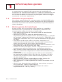
1.4 Warranty and Approvals
RAYCHEM heating cables and components are
approved for use in hazardous and nonhazardous
locations. Refer to the specific product data sheets
for details.
1.5 General Installation Notes
These notes are provided to assist the installer
throughout the installation process and should
be reviewed before the installation begins.
• Read all instruction sheets to familiarize
yourself with the products.
• Select the heating cable type and rating in
accordance with the Industrial Product
Selection and Design Guide (nVent literature
#H56550), or TraceCalc Pro software, or the
website design software.
• Ensure all pipes, tanks, etc., have been
released by the client for tracing prior to
installation of the heating cables.
• Typically, heating cables are installed at the
4 and 8 o’clock positions on a pipe.
• All heat-traced pipes, tanks, vessels, and
equipment must be thermally insulated.
• Do not install heating cables on equipment
operating above the heating cable’s maximum
rated temperature.
• The minimum bending radius for VPL
Power-Limiting cables is 3/4 inch (19 mm).
The minimum bending radius for
Self-Regulating cables is 1/2 inch (13 mm).
• Never install heating cables over expansion
joints without leaving slack in the cable.
• Do not energize cable when it is coiled or on the
reel.
• Never use tie wire or pipe straps to secure
heating cables.
6 | nVent.com

2
Heating Cable Selection
nVent.com | 7
The minimum installation temperature for
heating cables is –40°F (–40°C). Check the
design specification to make sure the proper
heating cable is installed on each pipe or
vessel. Refer to the Industrial Product Selection
and Design Guide, TraceCalc Pro or the nVent
web site, nVent.com, to select the proper heating
cable for your application.

3
Heating Cable Installation
8 | nVent.com
3.1 Heating Cable Storage
• Store the heating cable in a clean, dry place.
Temperature range:
–40°F (–40°C) to 140°F (60°C).
• Protect the heating cable from mechanical
damage.
3.2 Pre-Installation Checks
Check materials received:
• Review the heating cable design and compare
the list of materials to the catalog numbers of
heating cables and components received to
confirm that proper materials are on site. The
heating cable type and voltage is printed
on its jacket.
• Ensure that the heating cable voltage rating is
suitable for the service voltage available.
• Inspect the heating cable and components for
in-transit damage.
• Verify that there are no holes in the heating
cable jackets by conducting the insulation
resistance test (refer to Section 9) on each
reel of cable.
Check piping to be traced:
• Make sure all mechanical pipe testing
(i.e. hydrostatic testing/purging) is complete
and the system has been cleared by the client
for tracing.
• Walk the system and plan the routing of the
heating cable on the pipe.
• Inspect the piping for burrs, rough surfaces,
or sharp edges. Remove if necessary.
• Verify that any surface coatings are dry to
the touch.
8 | nVent.com

3
Heating Cable Installation
nVent.com | 9
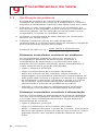
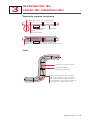
3.3 Installation
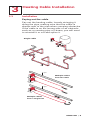
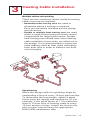
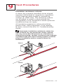
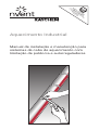
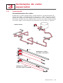
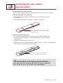
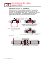
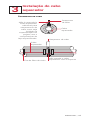
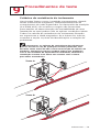
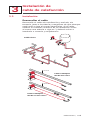
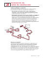
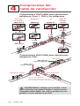
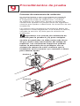
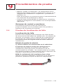
Paying out the cable
Pay out the heating cable, loosely stringing it
along the pipe, making sure that the cable is
always next to the pipe when crossing obstacles.
If the cable is on the wrong side of an obstacle
such as a crossing pipe or I-beam, you will need
to reinstall it or cut and splice it.
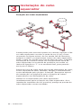
Single cable
Pipe
Pipe
Multiple cables
from two reels
Multiple cables
from a single reel
nVent.com | 9

3
Heating Cable Installation
10 | nVent.com
Heating cable paying out tips:
• Use a reel holder that pays out smoothly with
little tension. If heating cable snags, stop
pulling.
• Keep the heating cable strung loosely but close
to the pipe being traced to avoid interference
with supports and equipment.
• Meter marks on the heating cable can be used
to determine heater length.
• Protect all heating cable ends from moisture,
contamination, and mechanical damage.
When paying out the heating cable, AVOID:
• Sharp edges
• Excessive pulling force or jerking
• Kinking and crushing
• Walking on it, or running over it with equipment
WARNING: Fire and Shock Hazard. Do
not install damaged cable. Components and
cable ends must be kept dry before and during
installation.
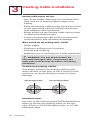
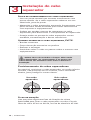
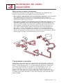
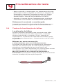
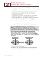
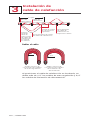
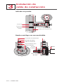
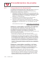
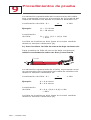
Positioning heating cables
If possible, position the heating cable on the
lower section of the pipe, at the 4 and 8 o’clock
positions, as shown below, to protect it from
damage.
Two heating cablesOne heating cable
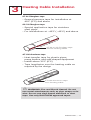
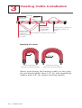
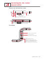
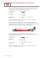
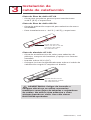
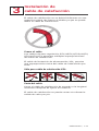
Attachment tapes
Use one of the following RAYCHEM attachment
tapes to secure the heating cable on the the
pipe: GT-66 or GS-54 fiberglass tape, or AT-180
aluminum tape.

3
Heating Cable Installation
nVent.com | 11
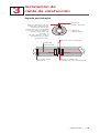
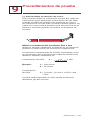
GT-66 fiberglass tape
• General purpose tape for installation at
40°F (5°C) and above
GS-54 fiberglass tape
• Special application tape for stainless
steel pipes
• For installations at –40°F (–40°C) and above
GT-66 or GS-54 glass tape
across heating cable
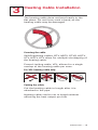
AT-180 aluminum tape
• Heat-transfer tape for plastic pipes,
pump bodies, and odd-shaped equipment
• Install above 32°F (0°C)
• Tape lengthwise over the heating cable as
required by the design
AT-180 aluminum tape
over heating cable
WARNING: Fire and Shock Hazard. Do not
use metal attachments such as pipe straps or tie
wire. Do not use vinyl-based electrical or duct
tape. Use only RAYCHEM approved tapes.

3
Heating Cable Installation
12 | nVent.com
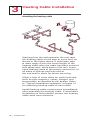
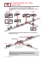
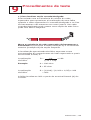
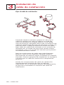
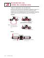
Attaching the heating cable
Starting from the end opposite the reel, tape
the heating cable on the pipe at every foot, as
shown in the figure above. If aluminum tape
is used, apply it over the entire length of the
heating cable after the cable has been secured
with glass tape. Work back to the reel. Leave
extra heating cable at the power connection, at
all sides of splices and tees and at
the end seal to allow for future servicing.
Allow a loop of extra cable for each heat sink,
such as pipe supports, valves, flanges, and
instruments, as detailed by the design. Refer
to "Typical installation examples" on page 16
for attaching heating cable to heat sinks.
Install heating cable components immediately
after attaching the heating cable. If immediate
installation is not possible, protect the heating
cable ends from moisture.

3
Heating Cable Installation
nVent.com | 13
Multiple cables and spiraling
There are two situations where multiple heating
cable runs may be required:
•
Redundant heat-tracing runs are used in
situations where a backup is required.
Each run should be installed per the design
specifications.
• Double or multiple heat-tracing runs are used
when a single heat-tracing run alone cannot
compensate for larger heat losses. Double
heat-tracing runs should have extra heating
cable installed at heat sinks, as called out in
the design. It is recommended to supply the
extra heating cable at heat sinks alternately
from both runs in order to balance out both
circuit lengths.
Spiral tracing
When the design calls for spiralling, begin by
suspending a loop at every 10-foot pipe section.
To determine the loop length, obtain a spiral
factor from the design and multiply by 10. For
example, if the spiral factor of 1.3 is called for,
leave a 13-foot loop of heating cable at every
10-foot section of pipe. Attach the loop to the
pipe at each interval using the appropriate
RAYCHEM attachment tape.

3
Heating Cable Installation
14 | nVent.com
10 feet
Glass tape
(typical)
Apply glass
tape before
spiraling
heating cable
on pipe
Pull heating cable loop length
Wrap loops
in opposite
directions
Tape after spiraling
heating cable on
pipe
Heating
cable
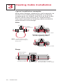
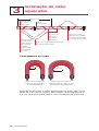
Bending the cable
Power-limiting
minimum bend radius
3/4"
Self-regulating
minimum bend radius
1/2"
When positioning the heating cable on the pipe,
do not bend tighter than 1/2" for self-regulating
cables and 3/4" for power-limiting cables.

3
Heating Cable Installation
nVent.com | 15
The heating cable does not bend easily in the
flat plane. Do not force such a bend, as the
heating cable may be damaged.
Crossing the cable
Self-Regulating cables, BTV, HBTV, QTVR, HQTV,
XTV, HXTV, KTV allow for multiple overlapping of
the heating cable.
Power-Limiting cable, VPL, allows for a single
overlap of the heating cable per zone.
For VPL heating cable only:
Cutting the cable
Cut the heating cable to length after it is
attached to the pipe.
Heating cable can be cut to length without
affecting the heat output per foot.

3
Heating Cable Installation
16 | nVent.com
Typical installation examples
Wrap pipe fittings, equipment, and supports as
shown in the following examples to properly
compensate for higher heat-loss at heat sinks
and to allow easy access for maintenance.
The exact amount of heating cable needed is
determined in the design.
Valve
Valve body
Multiple crossovers allowed
for self-regulating cables
Single crossover only, allowed
for power-limiting cables
Glass tape
Pipe
Heating cable
Pipe
Heating cable
Note: Cable loop length
varies depending on
heat loss.
Flange
Glass tape
(typical)
Heating cable
Loop length is twice
the diameter of the pipe.

3
Heating Cable Installation
nVent.com | 17
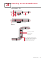
Pipe support shoe
Heating cable secured to pipe
Glass tape
Heating cable loop
Support shoe
Pipe
Elbow
Heating cable
Glass tape
(typical)
For pipe diameters of 2"
and larger, the heating
cable should be installed
on the outside (long)
radius of the elbow.

3
Heating Cable Installation
18 | nVent.com
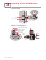
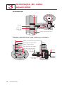
Pressure gauge
Heating cable
Glass tape
Pipe
Split case centrifugal pump
Glass tape
Pump discharge
Pump body
Heating cable
Pump
suction
Use AT-180
tape
Motor
To power connection

3
Heating Cable Installation
nVent.com | 19
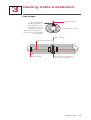
Pipe hanger
Heating cable
Heating cable
Glass tape Do not clamp heating
cable with support
Pipe hanger
Pipe hanger
No additional
heating cable is
required for pipe
hangers unless
called for in the
design specification,
then use loop length
specified.

4
Heating Cable Components
20 | nVent.com
4.1 General Component Information
RAYCHEM components must be used with
RAYCHEM self-regulating and power-limiting
heating cables. A complete circuit requires a power
connection and an end seal. Splices and tees are
used as needed.
Use the Industrial Product Selection and Design
Guide or TraceCalc Pro to select appropriate
components.
Installation instructions are included with the
component kit. Steps for preparing the heating
cable and connecting to components must be
followed.
RAYCHEM self-regulating and power-limiting
heating cables are parallel circuit design. Do not
twist the conductors together as this will result in a
short circuit.
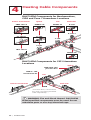
Component Installation Tips
• Connection kits should be mounted on top of the
pipe when practical. Electrical conduit leading
to power connection kits should have low-point
drains to keep condensation from accumulating
in the conduit. All heating cable connections must
be mounted above grade level.
• Special adapters are available for mounting on
small pipes. Be sure to use these adapters if
installing cables on pipes of 1 inch O.D. or less.
• Be sure to leave a service loop at all components
for future maintenance, except when temperature-
sensitive fluids are involved or when the pipe is
smaller than 1 inch.
• Locate junction boxes for easy access, but not
where they may be exposed to mechanical abuse.
• Heating cables must be installed over, not under,
pipe straps used to secure components.
• For VPL, cut cable 12" (30 cm) from last active
node (indentation) to be sure an inactive zone is
used to enter the component. Refer to component
installation instructions.
A página está carregando...
A página está carregando...
A página está carregando...
A página está carregando...
A página está carregando...
A página está carregando...
A página está carregando...
A página está carregando...
A página está carregando...
A página está carregando...
A página está carregando...
A página está carregando...
A página está carregando...
A página está carregando...
A página está carregando...
A página está carregando...
A página está carregando...
A página está carregando...
A página está carregando...
A página está carregando...
A página está carregando...
A página está carregando...
A página está carregando...
A página está carregando...
A página está carregando...
A página está carregando...
A página está carregando...
A página está carregando...
A página está carregando...
A página está carregando...
A página está carregando...
A página está carregando...
A página está carregando...
A página está carregando...
A página está carregando...
A página está carregando...
A página está carregando...
A página está carregando...
A página está carregando...
A página está carregando...
A página está carregando...
A página está carregando...
A página está carregando...
A página está carregando...
A página está carregando...
A página está carregando...
A página está carregando...
A página está carregando...
A página está carregando...
A página está carregando...
A página está carregando...
A página está carregando...
A página está carregando...
A página está carregando...
A página está carregando...
A página está carregando...
A página está carregando...
A página está carregando...
A página está carregando...
A página está carregando...
A página está carregando...
A página está carregando...
A página está carregando...
A página está carregando...
A página está carregando...
A página está carregando...
A página está carregando...
A página está carregando...
A página está carregando...
A página está carregando...
A página está carregando...
A página está carregando...
A página está carregando...
A página está carregando...
A página está carregando...
A página está carregando...
A página está carregando...
A página está carregando...
A página está carregando...
A página está carregando...
A página está carregando...
A página está carregando...
A página está carregando...
A página está carregando...
A página está carregando...
A página está carregando...
A página está carregando...
A página está carregando...
A página está carregando...
A página está carregando...
A página está carregando...
A página está carregando...
A página está carregando...
A página está carregando...
A página está carregando...
A página está carregando...
A página está carregando...
A página está carregando...
A página está carregando...
A página está carregando...
A página está carregando...
A página está carregando...
A página está carregando...
A página está carregando...
A página está carregando...
A página está carregando...
A página está carregando...
A página está carregando...
A página está carregando...
A página está carregando...
A página está carregando...
A página está carregando...
A página está carregando...
A página está carregando...
A página está carregando...
A página está carregando...
A página está carregando...
A página está carregando...
A página está carregando...
A página está carregando...
A página está carregando...
A página está carregando...
A página está carregando...
A página está carregando...
-
 1
1
-
 2
2
-
 3
3
-
 4
4
-
 5
5
-
 6
6
-
 7
7
-
 8
8
-
 9
9
-
 10
10
-
 11
11
-
 12
12
-
 13
13
-
 14
14
-
 15
15
-
 16
16
-
 17
17
-
 18
18
-
 19
19
-
 20
20
-
 21
21
-
 22
22
-
 23
23
-
 24
24
-
 25
25
-
 26
26
-
 27
27
-
 28
28
-
 29
29
-
 30
30
-
 31
31
-
 32
32
-
 33
33
-
 34
34
-
 35
35
-
 36
36
-
 37
37
-
 38
38
-
 39
39
-
 40
40
-
 41
41
-
 42
42
-
 43
43
-
 44
44
-
 45
45
-
 46
46
-
 47
47
-
 48
48
-
 49
49
-
 50
50
-
 51
51
-
 52
52
-
 53
53
-
 54
54
-
 55
55
-
 56
56
-
 57
57
-
 58
58
-
 59
59
-
 60
60
-
 61
61
-
 62
62
-
 63
63
-
 64
64
-
 65
65
-
 66
66
-
 67
67
-
 68
68
-
 69
69
-
 70
70
-
 71
71
-
 72
72
-
 73
73
-
 74
74
-
 75
75
-
 76
76
-
 77
77
-
 78
78
-
 79
79
-
 80
80
-
 81
81
-
 82
82
-
 83
83
-
 84
84
-
 85
85
-
 86
86
-
 87
87
-
 88
88
-
 89
89
-
 90
90
-
 91
91
-
 92
92
-
 93
93
-
 94
94
-
 95
95
-
 96
96
-
 97
97
-
 98
98
-
 99
99
-
 100
100
-
 101
101
-
 102
102
-
 103
103
-
 104
104
-
 105
105
-
 106
106
-
 107
107
-
 108
108
-
 109
109
-
 110
110
-
 111
111
-
 112
112
-
 113
113
-
 114
114
-
 115
115
-
 116
116
-
 117
117
-
 118
118
-
 119
119
-
 120
120
-
 121
121
-
 122
122
-
 123
123
-
 124
124
-
 125
125
-
 126
126
-
 127
127
-
 128
128
-
 129
129
-
 130
130
-
 131
131
-
 132
132
-
 133
133
-
 134
134
-
 135
135
-
 136
136
-
 137
137
-
 138
138
-
 139
139
-
 140
140
-
 141
141
-
 142
142
-
 143
143
-
 144
144


Raychem Industrial Heat-Tracing Guia de instalação
- Tipo
- Guia de instalação
- Este manual também é adequado para
em outras línguas
Artigos relacionados
Outros documentos
-
Megger MIT400/2 Series Manual do usuário
-
 nVent RAYCHEM E-100-A High-Profile End Seal Kit Manual do usuário
-
-
-
 nVent RAYCHEM RAYSTAT-EX-02 Mechanical Thermostat Guia de instalação
-
koban KCL-01 Manual do usuário
-
Tyco DigiTrace RAYSTAT-EX-02 Installation Instructions Manual
-
Danfoss heating cables Instruções de operação
-
Klein Tools 56115 Instruções de operação

