Berkel DOMINA Series Vertical Salumeria Slicer Manual do usuário
- Categoria
- Fatiadores
- Tipo
- Manual do usuário

DOMINA SERIES
SLG 315 - 350 - 370
SLL 315 - 350 - 370
SLH 315 - 350 -370
CODE: MAN-DOM-001
USER MANUAL
MANUALE D’USO
GEBRAUCHSANLEITUNG
MANUEL D’INSTRUCTIONS
NÁVOD K POUŽITÍ
BETJENINGSVEJLEDNING
EN
DE
CS
IT
FR
DA
MANUAL DEL USUARIO
HANDLEIDING
BRUKSANVISNING
MANUAL DE INSTRUÇÕES
MANUAL DE INSTRUCTIUNI
BRUKSANVISNING
NO
RO
NL
PT
ES
SV

1
2
(I)
(E-1) (F-1) (F-2)
(A) (D)
(B)
3
4
(L)
A
B
(M-1) (M-2) (M-3)

3
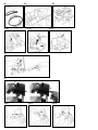
Fig. 1 - Abb. 1 - Obr. 1 - Afb. 1 - Bild 1
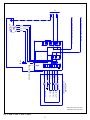
DOMINA SLG350 - SLG370
L
MA
CO
AR
C
M
ANTITAMPER
CONTROL PANEL
BROWN
BROWN
LED START
START N.O.
STOP N.C.
LED STOP
WHITE
GREEN
YELLOW
YELLOW
GREEN
LED
+ -
WHITE
BLUE
LED
+ -
T1
1
2
3
L2
L1 U
V
K1
MONO PHASE MOTOR 1 KW U-V
MONO PHASE POWER SUPPLY L1-L2
SELF RESTORE FUSE
M1
1
M
BLACK
WHITE or RED
X1
G
L1
L2
X1
14 µF
PEG350G-370G/SLG350-370
GREY
GREY
BLUE

4
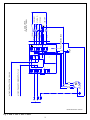
Fig. 1 - Abb. 1 - Obr. 1 - Afb. 1 - Bild 1
DOMINA SLG315
L
MA
CO
AR
C
M
ANTITAMPER
CONTROL PANEL
BROWN
BROWN
LED START
START N.O.
STOP N.C.
LED STOP
WHITE
GREEN
YELLOW
YELLOW
GREEN
LED
+ -
WHITE
BLUE
LED
+ -
T1
1
2
3
L2
L1 U
V
K1
MONO PHASE MOTOR 1 KW U-V
MONO PHASE POWER SUPPLY L1-L2
SELF RESTORE FUSE
M1
1
M
X1
G
L1
L2
X1
10 µF
BEG30G / BEG35-37B / PEG-SLG315 / PEG35B-Y
GREY
GREYGREY
BLACK
BLUE
RED
WHITE
WHITE

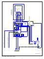
5
L
MA
CO
AR
C
M
ANTITAMPER
CONTROL PANEL
BROWN
BROWN
LED START
START N.O.
STOP N.C.
LED STOP
WHITE
GREEN
YELLOW
YELLOW
GREEN
LED
+ -
WHITE
BLUE
LED
+ -
T1
1
2
3
L2
L1 U
V
K1
MONO PHASE MOTOR 1 KW U-V
MONO PHASE POWER SUPPLY L1-L2
SELF RESTORE FUSE
M1
1
M
X1
G
L1
L2
X1
10 µF
BEG30G / BEG35-37B / PEG-SLG315 / PEG35B-Y
GREY
GREYGREY
BLACK
BLUE
RED
WHITE
WHITE
Fig. 1 - Abb. 1 - Obr. 1 - Afb. 1 - Bild 1
DOMINA SLH315-350-370
DOMINA SLL315-350-370
L
MA
CO
AR
C
M
ANTITAMPER
CONTROL PANEL
BROWN
BROWN
LED START
START N.O.
STOP N.C.
LED STOP
WHITE
GREEN
YELLOW
YELLOW
GREEN
LED
+ -
WHITE
BLUE
LED
+ -
T1
1
2
3
L2
L1 U
V
K1
MONO PHASE MOTOR 1 KW U-V
MONO PHASE POWER SUPPLY L1-L2
SELF RESTORE FUSE
M1
1
M
BLACK
WHITE or RED
BLUE
X1
G
L1
L2
X1
BLUE
GREY
BLUE
14 µF
SLC300-330-350/SLH-SLL-PES-PEM315-350-370

6
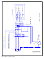
Fig. 1 - Abb. 1 - Obr. 1 - Afb. 1 - Bild 1
DOMINA SLG315-350-370
DOMINA SLL315-350-370
DOMINA SLH 315-350-370
L
MA
CO
AR
C
M
ANTITAMPER
CONTROL PANEL
BROWN
BROWN
LED START
START N.O.
STOP N.C.
LED STOP
WHITE
GREEN
YELLOW
YELLOW
GREEN
LED
+ -
WHITE
WHITE
LED
+ -
T1
1
2
3
L2
L1
L3 W
U
V
K1
THREE PHASE MOTOR 1 KW U-V-W
THREE PHASE POWER SUPPLY L1-L2-L3
SELF RESTORE FUSE
M1
3
M
BLACK
BLUE
BLUE
BLACK
X1
L3
G
L1
L2
X1
IMP. ELE. 14 400V/50 Hz
WHITE OR RED OR BROWN
WHITE OR RED OR BROWN

7
USER MANUAL: Electric Slicers Domina
SLL 315 - 350 - 370 | SLH 315 - 350 - 370 | SLG 315 - 350 - 370
EN
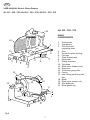
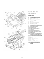
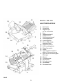
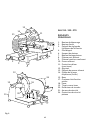
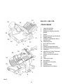
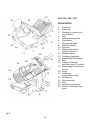
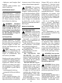
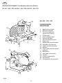
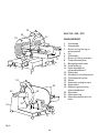
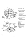
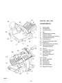
Fig. 2
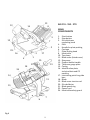
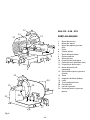
SLL 315 - 350 - 370
MAIN
COMPONENTS
1. Start button
2. Stop button
3. Slice thickness
regulating knob
4. Foot
5. Handle for plate pushing
6. Carriage
7. Plate locking knob
8. Meat table
9. Sliding overplate
10. Top clamp
11. Blade cover (blade cover)
12. Sharpener
14. Thickness gauge plate
15. Casing
17. Lubricating point for guide
bars
18. Blade
19. Blade cover tension rod
20. Slice deector
21. Blade guard ring
123
12
19 10
18
20
21
17
4
10
5
5
9
67
8
9
11
14
15
L
MA
CO
AR
C
M
ANTITAMPER
CONTROL PANEL
BROWN
BROWN
LED START
START N.O.
STOP N.C.
LED STOP
WHITE
GREEN
YELLOW
YELLOW
GREEN
LED
+ -
WHITE
WHITE
LED
+ -
T1
1
2
3
L2
L1
L3 W
U
V
K1
THREE PHASE MOTOR 1 KW U-V-W
THREE PHASE POWER SUPPLY L1-L2-L3
SELF RESTORE FUSE
M1
3
M
BLACK
BLUE
BLUE
BLACK
X1
L3
G
L1
L2
X1
IMP. ELE. 14 400V/50 Hz
WHITE OR RED OR BROWN
WHITE OR RED OR BROWN

8
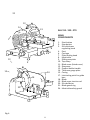
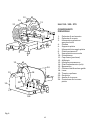
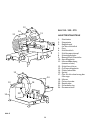
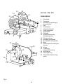
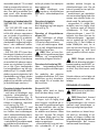
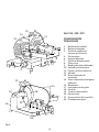
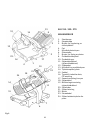
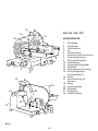
SLH 315 - 350 - 370
MAIN
COMPONENTS
1. Start button
2. Stop button
3. Slice thickness
regulating knob
4. Foot
6. Carriage
7. Plate locking knob
8. Meat table
9. Sliding overplate
10. Top clamp
11. Blade cover (blade cover)
12. Sharpener
13. Product holder handle
14. Thickness gauge plate
15. Casing
17. Lubricating point for guide
bars
18. Blade
19. Blade cover tension rod
20. Slice deector
21. Blade guard ring
24. Meat table safety guard
Fig. 2
12
3
12
13
19
17
20
21 18
24
4
7
6
8
9
10
11
12
14
21
15

9
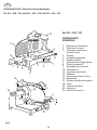
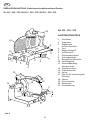
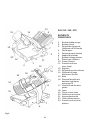
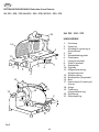
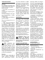
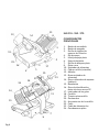
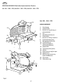
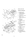
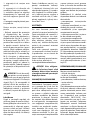
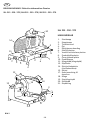
Fig. 2
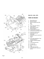
SLG 315 - 350 - 370
MAIN
COMPONENTS
1. Start button
2. Stop button
3. Slice thickness
regulating knob
4. Foot
5. Handle for plate pushing
6. Carriage
7. Plate locking knob
8. Meat table
10. Top clamp
11. Blade cover (blade cover)
12. Sharpener
13. Product holder handle
14. Thickness gauge plate
15. Casing
16. Identication plate,
technical data and CE
marking
17. Lubricating point for guide
bars
18. Blade
19. Blade cover tension rod
20. Slice deector
21. Blade guard ring
23. Power cord
24. Meat table safety guard
1
2
3
12 13
13
14
18
19
17
24
16
23
4
6
7
7
5
10
11
14 8
15
21

10
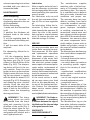
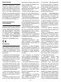
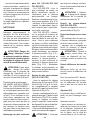
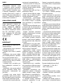
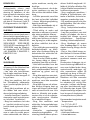
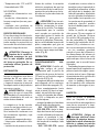
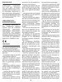
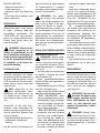
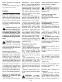
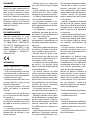
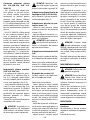
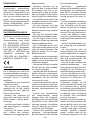
DESCRIPTION
Circular blade professional
slicer machine suitable for
cutting only the food products
of the types and within the di-
mensional limits indicated in
this manual. The main parts of
the machine are shown in the
general component diagram
reported in picture 2. Electrical
diagrams are reported in pic-
ture 1.
DECLARATION
OF CONFORMITY
The machines described in this
manual comply with Direc-
tives 2006/42/CE, 2006/95/
CE, 2004/108/CE, 2003/108/
CE, 2011/65/CE, Regulation
(EC) 1935/2004 and related
harmonized standards as EN
1974:1998 +A1, EN60204-1,
EN60335-1, EN60335-2-64.
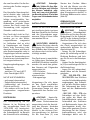
SAFETY
Pay attention to the following
basic safety precautions:
- read all the instructions be-
fore using the machine;
- this product is not intended
to be used by children;
- operate the machine only if
properly trained and in perfect
psycho-physical conditions;
- do not use the machine in any
way other than what indicated
in this manual;
- use the machines only in full
structural, mechanical and sys-
tem efciency;
- install the machine in con-
formity to the instructions
indicated in the “Installation”
section;
- install the machine in a loca-
tion out of the reach of person-
nel unauthorized to operate it
and especially out of the reach
of minors;
- stay highly concentrated
when using the machine and
avoid any distraction during
use;
- do not allow the machine to
be used by others who have
not read and fully understood
the content of this manual;
- do not wear baggy clothing or
clothing with open sleeves;
- do not allow anyone else,
other than the operator, to ap-
proach during product cutting
operations;
- do not remove, cover or
modify the tags located on the
machine body and, in case of
damage of these, replace them
promptly;
- do not remove the transpar-
ent guards and do not modify
or bypass any mechanical and
electrical protective devices;
- slice only the permitted prod-
ucts, do not attempt cuts on
prohibited type products;
- always keep clean and dry the
sliced product resting surface,
the work area all around the
machine and the operator oor
area;
- do not use the machine as
a resting surface and do not
place any objects on it other
than food used for cutting op-
erations;
- do not use the slicer when,
due to normal wear, the dis-
tance between the edge of
the blade and the blade guard
ring exceeds 6 mm. In this case,
contact the manufacturer or to
one of the Authorized Service
Centers to change the blade;
- do not use the machine with
temporary or non-insulated
cables, power strips or exten-
sion cords;
- periodically check the condi-
tion of the power supply cord
on the machine body. When
necessary, have qualied per-
sonnel replacing it;
- immediately stop the ma-
chine in the event of a defect,
abnormal operation, suspicion
of breakdown, incorrect move-
ment, unusual noises;
- before cleaning or carrying
out maintenance, disconnect
the machine from the electri-
cal supply;
- use protective gloves for
cleaning and maintenance op-
erations;
- place and remove the goods
to be sliced on the sliding plate
only with the carriage com-
pletely pulled back and with
the thickness adjustment knob
placed in the safety position
(on the 0 position);
- for movement of the meat
table during cutting operations
use only the handle located on
the arm or the product presser
grip;
- never put your hands on the
food product while slicing. Al-
ways keep your hands behind
the protection devices and far
from the blade;
- use of cutting accessories
which were not provided by
the manufacturer with the ma-
chine is prohibited.
The manufacturer declines any
responsibility coming from in-
appropriate use, modications
and/or repairs carried out by
the user or unauthorized per-
sonnel, use of replacement
parts that are not original or
not specic for the machine
model.
The machine shall not be used
in open areas and/or areas
which are exposed to atmos-
pheric agents and in environ-
ments with vapors, fumes or
corrosive and/or abrasive pow-

11
ders, with risk of re or explo-
sion and in any case where the
use of antiexplosive compo-
nents is required.
Operating conditions:
- Temperature
from -5°C to +40°C
- Max. humidity 95%
DO NOT SLICE:
- frozen food products;
- food products with bones;
- vegetables;
- any other product not intend-
ed for food use.
RESIDUAL RISKS
The safety ring around the
blade is made in conformity
to European standards EN
1974:1998 +A1 but, in order
to allow the sharpening oper-
ations, the protection in the
sharpening area may not en-
tirely eliminate the risk of cut-
ting.
WARNING! Risk of injury
from sharp blade! During
the blade cleaning and sharpen-
ing operations, pay extra atten-
tion to keep your hands as far as
possible from the unprotected
area. Use of protective gloves is
recommended.
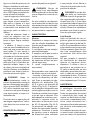
INSTALLATION
OF THE MACHINE
Install the machine at a maxi-
mum height of 90 cm, on a at,
smooth and dry surface suita-
ble for supporting the weight
of the machine itself plus the
products to be sliced.
WARNING: Verify that
there are no obstacles to
the meat table travel and to the
loading of products.
The machine must be installed
in the immediate vicinity of an
EEC standard outlet connect-
ed to an electrical supply sys-
tem which is in conformity with
the prevailing regulations for:
- magneto-thermic protection;
- automatic differential switch;
- earthing system.
Before carrying out electrical
hook up verify that the charac-
teristics of the electrical power
supply is in accordance with
those indicated on the machine
information plate.
WARNING! For machines
with 3-phase motor,
check the blade orientation.
Push the start button (1) to
switch on the machine: looking
at the blade from the operator
side, the blade has to rotate
downwardly (Fig. B).
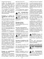
OPERATION
WARNING! Risk of injury from
sharp blade! Check that
the thickness adjustment
knob (3)is in the safety position
(on the 0 position) (Fig. A).
- Be sure that the machine is
switched off, if not push the
stop button (2);
- pull the meat table (8) all the
way back (towards the opera-
tor) in the loading position;
- lift the product holder (10)
into the standby position;
- Place the product to be
sliced on the sliding meat table:
-SLL 315-350-370, SLH
315-350-370: move the slid-
ing meat table away from the
thickness gauge plate. Set
the product to be sliced on
the plate near the table edge
on the operator side;
-SLG 315-350-370: set the
product to be sliced on the
plate against the wall of the
meat table, near the edge
of the table on the operator
side; lock using the prod-
uct press holder, applying
pressure; in the gravity ver-
sion, the product will press
against the plate from the
force of its own weight;
- adjust the slice thickness
with the special knob (3). Acti-
vate the blade (18) by pressing
the start button (1). Grip the
product holder handle (13) and
start an alternative cutting
motion;
- on gravity models, when the
weight or size of the goods
do not allow a proper cutting
for reasons of gravity, use the
product holder handgrip;
- at the end of the cutting op-
erations return the thickness
adjustment knob to the safety
position and pull the meat ta-
ble back. Stop the blade motion
by pressing the stop button (2);
- move the sliding meat table
away from the gauge plate and
remove the product.
CLEANING
Before using, clean the ma-
chine at least once a day - or
more often if necessary - and
always after a long period of
inactivity.
WARNING! Risk of electric
shock! Before cleaning,
disconnect the plug from the
electrical mains socket.
WARNING! Risk of injury
from sharp blade! Check
that the thickness adjustment
knob (3) is in the safety posi-
tion (on the 0 position) (Fig. A).
Products for cleaning:
use only water and biodegrad-
able mild detergent with PH
!
!
!
!
!
!

12
7-8, using a soft, spongy cloth
and a semi-rigid nylon brush
for the sharp areas of the plate
and the product holder. Do not
clean the machine with jets of
water or steam or similar meth-
ods. DO NOT DISHWASH.
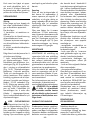
Cleaning the sliding meat ta-
bles models SLL 315-350-370,
SLH 315-350-370
- SLL 315-350-370: pull the
sliding meat table to the end;
a metallic click noties the
operator that the meat table
is locked. Lift the meat table all
the way up (Fig. E-1). Clean the
sliding meat table and repeat
operations in the reverse order
to reposition the sliding meat
table.
- SLH 315-350-370: loosen,
rotating the product presser
clamp on the meat table in the
anticlockwise direction. Pull
the sliding meat table to the
end; a metallic click noties the
operator that the meat table is
locked. Move the sliding meat
table away from the thickness
gauge plate and lift the product
presser (Fig. F-1). Clean the sli-
ding meat table and lower the
product press holder. Lift the
sliding meat plate and clean
the meat table (Fig. F-2). Rele-
ase the meat table, rotating the
product presser clamp in the
clockwise direction.
Removing the meat table (SLG
315 - 350 - 370)
- with the regulating knob for
slice thickness (3) in the safety
position (Fig. A, Fig. D-1), pull
back the plate support (6) all
the way until the travel limit
toward the operator (Fig. D-2);
- fully rotate the locking knob
in the anticlockwise direction
(Fig. D-3) keeping the support
at the travel limit, until the
safety locking device inter-
venes on the gauge plate;
- remove the meat table from
the top, sliding it off from the
support.
WARNING! Make sure
that the product press
holder is lowered on the table
before removing the plate sup-
port.
WARNING! Keep the reg-
ulating knob for slice thick-
ness in the safety position “0”.
Removing the product press
holder (SLG 315 - 350 -370)
rotate the grip and remove the
product press holder (Fig. G).
Removing the blade cover (11)
- rotating in the anticlockwise
direction, loosen the blade cov-
er tension rod grip (19);
- press the tension rod grip
and raise the blade cover to re-
move it.
WARNING! Once the
blade cover has been re-
moved, an interlocking device
stops the blade rotation.
Removing the slice deector
(20)
For Gravity versions SLG 315
- 350 - 370: loosen the locking
pin and rotate the slice deec-
tor downward to remove it
from the pin.
Loosen the xing screw(s) and
remove the slice deector.
Sharpener (12)
Clean the body with a damp
cloth. Do not submerge in water.
Cleaning:
- the blade: press a damp cloth
on the surface of the blade and
move it slowly from the center
toward the outside on the
blade cover side and the oppo-
site side. In the same way dry it
using a dry cloth. NEVER turn
on the machine while cleaning
the blade;
- the safety ring: use a soft
brush to clean the area be-
tween the blade and the safe-
ty ring. Be careful NOT to put
your hands close to the blade;
- the machine body: use a damp
cloth or a sponge. Dry carefully;
- the sharpener: 1) clean the
body with a damp cloth and the
springs with a semi-rigid brush.
2) do not submerge the sharp-
ener in water. The sharpening
wheel can easily be removed
from the sharpening unit, re-
moving it in the direction of the
arrow (Fig. I). Keep the wheel
clean for correct sharpening.
Remove dirt and grease with
alcohol and a semi-rigid nylon
brush.
WARNING! Clean all
dismantled parts indivi-
dually in lukewarm water and
NON-AGGRESSIVE dishwa-
sher detergent, using a bottle
brush or cloth. Rinse in hot wa-
ter and dry.
Proceed with assembly opera-
tions, following the directions
described in reverse order.
REMOVING THE BLADE
WARNING! Use original
devices only!
WARNING! Danger of
being cut! Use only after
carefully reading the operating
instructions supplied with the
device.
If a blade removal device has
been purchased, it is recom-
mended that you follow the
!
!
!
!
!
!

13
!
relevant operating instructions
provided with your device to
remove the blade.
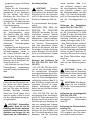
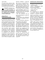
MAINTENANCE
Blade Sharpening
Frequency and duration of
sharpening depend on the use
of the equipment.
Before sharpening:
1. make sure that the machine
is off;
2. position the thickness ad-
justment knob in the safety
position;
3. set the regulating knob for
slice thickness in the safety posi-
tion;
4. pull the meat table all the
way back.
For sharpening, follow the in-
struction:
- Lift the sharpening device
guard cover. Pull the unlock-
ing device grip (Fig. M-1) and
rotate it in the direction of the
blade (Fig. M-2). The sharpen-
ing device will lock in the cor-
rect position. Press the start
button to start up the machine.
Slightly rotate the lever, bring-
ing the two wheels in contact
with the blade for about 10-15
seconds (Fig. M-3). Sharpening
and deburring occur simulta-
neously. Press the stop but-
ton and pull the device grip to
move it back to the initial po-
sition. Lower the sharpening
device guard cover.
WARNING! The sharp-
ening wheel can easily
be removed from the sharp-
ening unit, removing it in the
direction of the arrow (Fig. I).
Keep the wheel clean for cor-
rect sharpening. Remove dirt
and grease with alcohol and a
semi-rigid nylon brush.
Lubrication
After a regular period of use, it
may be necessary to lubricate
the carriage guides. We recom-
mend executing this operation
every 1 month.
For lubrication, only use acid
free oil (we recommend Vase-
line oil). Do not use vegetable
oil.
For lubricating, follow the in-
struction: 1) move the meat
table towards the operator; 2)
insert the oiler in the special
hole and pour a small amount
of oil; 3) remove the oiler and
slide the carriage 3-4 times.
SERVICE
No user-serviceable parts are
inside. Refer servicing to qual-
ied personnel. All the repair
and replacement operations
(like blade replacement, re-
placement of the motor belt,
replacement of the sub-basap-
late electrical system compo-
nents, repair of structural parts,
repair and/or re-placement of
sub-baseplate components, or
similar) shall be executed exclu-
sively by personnel authorized
by the manufacturer.
In the event service is need-
ed, you may return your food
slicer to the manufacturer or
to one of the Authorized Ser-
vice Centers. For information
about service centers please
contact us at:
service@berkelinternational.com.
WARNING! The blade re-
placement is mandatory
if distance between the edge of
the blade and the internal edge
of the guard exceeds 6 mm.
WARRANTY
AND RESPONSIBILITY
The manufacturer supplies
machines with a limited war-
ranty of 24 months from the
purchasing date. The warran-
ty is extended only to defects
that arise under intended use
conditions and proper use.
The warranty does not cover
defects resulting from faults
caused by transport, purchas-
er’s incompetence or negli-
gence, improper installation
or earthing, unauthorised in-
terventions, natural wear and
tear, voltage variations greater
than 10% of the nominal value.
Moreover, the warranty does
not cover components intrin-
sically subject to wear, such as
blades and grinders, except in
the event of evident manufac-
turing defects.
The manufacturer declines any
direct and indirect responsibil-
ity coming from:
- failure to observe the instruc-
tions in this manual;
- use which does not conform
to prevailing specic regula-
tions in the country of instal-
lation;
- unauthorised modications
and/or repairs carried out on
the machine;
- use of non original accesso-
ries and replacement parts;
- exceptional events.
Transfer of ownership of the
machine automatically defaults
the manufacturer’s liability for
the machine in question with
the exception of observance of
directive 2006/42/CE (liability
for any manufacturing defects
of the product).
The Identication tag on the
base-plate indicates manufac-
turer, machine, technical infor-
mation and CE marking.
!

14
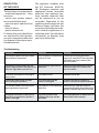
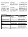
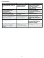
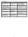
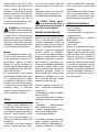
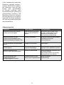
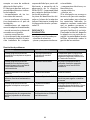
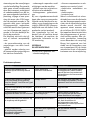
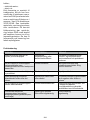
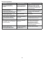
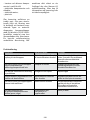
Troubleshooting
PROBLEM REASON REMEDY
The machine does not start when
the on button is pressed Lack of power or defective
control circuit Check that the plug has been
correctly inserted. If the machine
still does not start, contact the
service center
The machine starts when the on
button is pressed but the operation
indicator light does not turn on
The indicator light may be
defective Do not use the machine with the
indicator light off. Contact the
service center
Excessive resistance to cutting of
the product The blade is dull Sharpen the blade
The blade slows down or stops
while cutting the product The drive belt may be
loose or damaged Contact the service center in
order to tension or replace the belt
The machine does not stop when
the stop button is pressed The control circuit may be
defective Immediately stop the machine,
removing the plug from the mains
outlet. Contact the service center
Excessive resistance in motion of
the sliding components (product
holder, carriage)
The lubrication of the
sliding guide may not be
sufcient
Carry out periodical lubrication as
described in this manual
DEMOLITION
OF THE SLICER
The machines are comprised of:
- aluminum/magnesium alloy
structure;
- inserts and various compo-
nents and stainless steel;
- electrical parts and electrical
cables;
- electric motor;
- plastic material, etc.
If dismantling and demolition
are entrusted to third parties,
use only companies authorized
for disposal of the above-men-
tioned materials.
The appliance complies with
the EU Directive 2012/19/
UE. Packaging materials and
appliances contain recyclable
materials. Your appliance con-
tains valuable materials that
can be recovered or can be
recyclable. Separation of the
remaining waste materials into
different types facilitates the
recycling of valuable raw mate-
rials. Leave the appliances at a
collection point. You can obtain
information on disposal from
your local authorities.

15
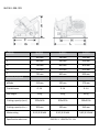
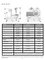
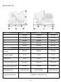
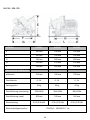
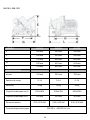
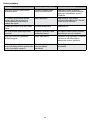
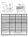
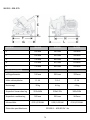
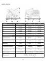
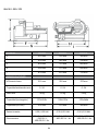
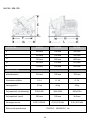
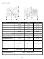
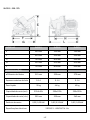
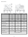
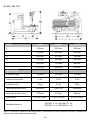
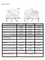
SLG 315 - 350 -370
E500 mm 540 mm 540 mm
420 mm 490 mm 490 mm
740 mm 800 mm 800 mm
525 mm 615 mm 615 mm
750 mm 800 mm
315 mm 350 mm
0 -14 0 -14
32 kg 44 kg
255x160h 300x195h
205 mm 250 mm
0,30 | 0,35 kW 0,30 | 0,35 kW0,25 | 0,30 kW
230/50/1 - 400/50/3 V - Hz
300x210h
265 mm
890 mm
370 mm
0 -14
49 kg
E
F
G
H
L
Specication electrical
Motor rating
Cutting capacity (circ.)
Cutting capacity (rect.)
Net weight
Cut thickness
ø Blade
SPECIFICATIONS
MODEL SLG315 SLG350 SLG370

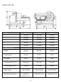
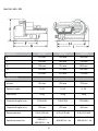
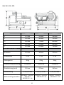
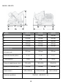
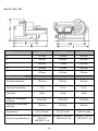
16
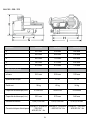
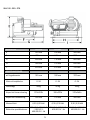
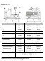
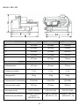
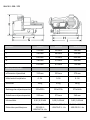
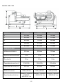
F
E
450 mm
515 mm
460 mm
550 mm
530 mm
560 mm
650 mm 710 mm 800 mm
560 mm 570 mm 640 mm
670 mm 670 mm 750 mm
315 mm 350 mm
0 -24 0 -24
38 kg 45 kg
270x225h 320x270h
225 mm 270 mm
0,30 | 0,35 kW 0,30 | 0,35 kW0,30 | 0,35 kW
120/60/1 - 220/60/1
- 230/50/1 -
400/50/3 V - Hz
120/60/1 - 220/60/1
- 400/50/3 V - Hz
120/60/1 - 230/50/1
- 400/50/3 V - Hz
370x260h
260 mm
370 mm
0 -24
56 kg
G
H
I
Specication electrical
Motor rating
Cutting capacity (circ.)
Cutting capacity (rect.)
Net weight
Cut thickness
ø Blade
SPECIFICATIONS
MODEL SLH315 SLH350 SLH370
SLH 315 - 350 - 370

17
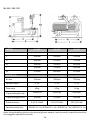
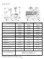
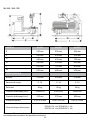
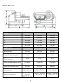
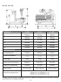
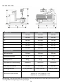
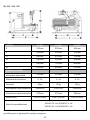
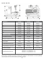
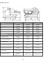
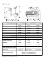
SLL 315 - 350 - 370
E510 mm 550 mm 560 mm
450 mm 450 mm 530 mm
640 mm 670 mm 720 mm
560 mm 590 mm 640 mm
650 mm
670 mm
710 mm
680 mm
315 mm 350 mm
0 -14 0 -14
40 kg 45 kg
290x225h 320x270h
225 mm 270 mm
0,30 | 0,35 kW 0,30 | 0,35 kW0,30 | 0,35 kW
120/60/1 V - Hz | 220/60/1 V - Hz | 230/50/1 V - Hz | 400/50/3 V - Hz
350x280h
280 mm
800 mm
670 mm
370 mm
0 -14
56 kg
E
F
G
H
I
M
Specication electrical
Motor rating
Cutting capacity (circ.)
Cutting capacity (rect.)
Net weight
Cut thickness
ø Blade
SPECIFICATIONS
MODEL SLL315 SLL350 SLL370
Note: As we actually strive to improve our products, specications are necessarily subject to change
without notice.

18
MANUALE D’USO: Affettatrici elettriche Domina
SLL 315 - 350 - 370 | SLH 315 - 350 - 370 | SLG 315 - 350 - 370
IT
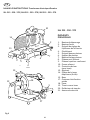
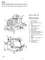
Fig. 2
SLL 315 - 350 - 370
COMPONENTI
PRINCIPALI
1. Pulsante di avviamento
2. Pulsante di arresto
3. Manopola regolazione
spessore fetta
4. Piedino
5. Maniglia spingipiatto
6. Supporto piatto
7. Manopola bloccaggio piatto
8. Piatto portamerce
9. Soprappiatto scorrevole
10. Pressamerce
11. Coprilama (paralama)
12. Aflatoio
14. Piastra spessimetro (vela)
15. Basamento
17. Oliatore lubricazione guide
18. Lama
19. Tirante coprilama
20. Parafetta
21. Anello di sicurezza
123
12
19 10
18
20
21
17
4
10
5
5
9
67
8
9
11
14
15

19
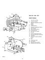
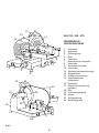
Fig. 2
SLH 315 - 350 - 370
COMPONENTI
PRINCIPALI
1. Pulsante di avviamento
2. Pulsante di arresto
3. Manopola regolazione
spessore fetta
4. Piedino
6. Supporto piatto
7. Manopola bloccaggio piatto
8. Piatto portamerce
9. Soprappiatto scorrevole
10. Pressamerce
11. Coprilama (paralama)
12. Aflatoio
13. Maniglia pressamerce
14. Piastra spessimetro (vela)
15. Basamento
17. Oliatore lubricazione guide
18. Lama
19. Tirante coprilama
20. Parafetta
21. Anello di sicurezza
24. Protezione di sicurezza
piatto
123
12
13
19
17
20
21
18
24
4
7
6
8
9
10
11
12
14
21
15

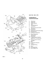
20
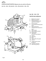
SLG 315 - 350 - 370
COMPONENTI
PRINCIPALI
1. Pulsante di avviamento
2. Pulsante di arresto
3. Manopola regolazione
spessore fetta
4. Piedino
5. Maniglia spingipiatto
6. Supporto piatto
7. Manopola bloccaggio piatto
8. Piatto portamerce
10. Pressamerce
11. Coprilama (paralama)
12. Aflatoio
13. Maniglia pressamerce
14. Piastra spessimetro (vela)
15. Basamento
16. Targhetta di identicazione,
dati tecnici e marcatura CE
17. Oliatore lubricazione guide
18. Lama
19. Tirante coprilama
20. Parafetta
21. Anello di sicurezza
23. Cavo di alimentazione
24. Protezione di sicurezza
piatto
1
2
3
12 13
13
14
18
19
17
24
16
23
4
6
7
7
5
10
11
14 8
15
21
A página está carregando...
A página está carregando...
A página está carregando...
A página está carregando...
A página está carregando...
A página está carregando...
A página está carregando...
A página está carregando...
A página está carregando...
A página está carregando...
A página está carregando...
A página está carregando...
A página está carregando...
A página está carregando...
A página está carregando...
A página está carregando...
A página está carregando...
A página está carregando...
A página está carregando...
A página está carregando...
A página está carregando...
A página está carregando...
A página está carregando...
A página está carregando...
A página está carregando...
A página está carregando...
A página está carregando...
A página está carregando...
A página está carregando...
A página está carregando...
A página está carregando...
A página está carregando...
A página está carregando...
A página está carregando...
A página está carregando...
A página está carregando...
A página está carregando...
A página está carregando...
A página está carregando...
A página está carregando...
A página está carregando...
A página está carregando...
A página está carregando...
A página está carregando...
A página está carregando...
A página está carregando...
A página está carregando...
A página está carregando...
A página está carregando...
A página está carregando...
A página está carregando...
A página está carregando...
A página está carregando...
A página está carregando...
A página está carregando...
A página está carregando...
A página está carregando...
A página está carregando...
A página está carregando...
A página está carregando...
A página está carregando...
A página está carregando...
A página está carregando...
A página está carregando...
A página está carregando...
A página está carregando...
A página está carregando...
A página está carregando...
A página está carregando...
A página está carregando...
A página está carregando...
A página está carregando...
A página está carregando...
A página está carregando...
A página está carregando...
A página está carregando...
A página está carregando...
A página está carregando...
A página está carregando...
A página está carregando...
A página está carregando...
A página está carregando...
A página está carregando...
A página está carregando...
A página está carregando...
A página está carregando...
A página está carregando...
A página está carregando...
A página está carregando...
A página está carregando...
A página está carregando...
A página está carregando...
A página está carregando...
A página está carregando...
A página está carregando...
A página está carregando...
A página está carregando...
A página está carregando...
A página está carregando...
A página está carregando...
A página está carregando...
A página está carregando...
A página está carregando...
A página está carregando...
A página está carregando...
A página está carregando...
A página está carregando...
A página está carregando...
A página está carregando...
A página está carregando...
A página está carregando...
A página está carregando...
A página está carregando...
A página está carregando...
A página está carregando...
A página está carregando...
A página está carregando...
A página está carregando...
A página está carregando...
A página está carregando...
A página está carregando...
A página está carregando...
A página está carregando...
-
 1
1
-
 2
2
-
 3
3
-
 4
4
-
 5
5
-
 6
6
-
 7
7
-
 8
8
-
 9
9
-
 10
10
-
 11
11
-
 12
12
-
 13
13
-
 14
14
-
 15
15
-
 16
16
-
 17
17
-
 18
18
-
 19
19
-
 20
20
-
 21
21
-
 22
22
-
 23
23
-
 24
24
-
 25
25
-
 26
26
-
 27
27
-
 28
28
-
 29
29
-
 30
30
-
 31
31
-
 32
32
-
 33
33
-
 34
34
-
 35
35
-
 36
36
-
 37
37
-
 38
38
-
 39
39
-
 40
40
-
 41
41
-
 42
42
-
 43
43
-
 44
44
-
 45
45
-
 46
46
-
 47
47
-
 48
48
-
 49
49
-
 50
50
-
 51
51
-
 52
52
-
 53
53
-
 54
54
-
 55
55
-
 56
56
-
 57
57
-
 58
58
-
 59
59
-
 60
60
-
 61
61
-
 62
62
-
 63
63
-
 64
64
-
 65
65
-
 66
66
-
 67
67
-
 68
68
-
 69
69
-
 70
70
-
 71
71
-
 72
72
-
 73
73
-
 74
74
-
 75
75
-
 76
76
-
 77
77
-
 78
78
-
 79
79
-
 80
80
-
 81
81
-
 82
82
-
 83
83
-
 84
84
-
 85
85
-
 86
86
-
 87
87
-
 88
88
-
 89
89
-
 90
90
-
 91
91
-
 92
92
-
 93
93
-
 94
94
-
 95
95
-
 96
96
-
 97
97
-
 98
98
-
 99
99
-
 100
100
-
 101
101
-
 102
102
-
 103
103
-
 104
104
-
 105
105
-
 106
106
-
 107
107
-
 108
108
-
 109
109
-
 110
110
-
 111
111
-
 112
112
-
 113
113
-
 114
114
-
 115
115
-
 116
116
-
 117
117
-
 118
118
-
 119
119
-
 120
120
-
 121
121
-
 122
122
-
 123
123
-
 124
124
-
 125
125
-
 126
126
-
 127
127
-
 128
128
-
 129
129
-
 130
130
-
 131
131
-
 132
132
-
 133
133
-
 134
134
-
 135
135
-
 136
136
-
 137
137
-
 138
138
-
 139
139
-
 140
140
-
 141
141
-
 142
142
-
 143
143


Berkel DOMINA Series Vertical Salumeria Slicer Manual do usuário
- Categoria
- Fatiadores
- Tipo
- Manual do usuário
em outras línguas
- español: Berkel DOMINA Series Vertical Salumeria Slicer Manual de usuario
- français: Berkel DOMINA Series Vertical Salumeria Slicer Manuel utilisateur
- italiano: Berkel DOMINA Series Vertical Salumeria Slicer Manuale utente
- Nederlands: Berkel DOMINA Series Vertical Salumeria Slicer Handleiding
- dansk: Berkel DOMINA Series Vertical Salumeria Slicer Brugermanual
- română: Berkel DOMINA Series Vertical Salumeria Slicer Manual de utilizare
Artigos relacionados
Outros documentos
-
Axis Axis VOLANO Series Manual do usuário
-
Essentials BES300 Essence of Salumeria Manual do usuário
-
Sammic GAE-350 Manual do usuário
-
-
 Elma CFD 250 XL Manual do proprietário
-
 Centerline EDGE Slicer Manual do usuário
-
-
Weston 83-0850-W Guia de usuario

