Yamaha DVX-S301 Manual do usuário
- Categoria
- Leitores de DVD
- Tipo
- Manual do usuário

YAMAHA ELECTRONICS CORPORATION, USA
6660 ORANGETHORPE AVE., BUENA PARK, CALIF. 90620, U.S.A.
YAMAHA CANADA MUSIC LTD.
135 MILNER AVE., SCARBOROUGH, ONTARIO M1S 3R1, CANADA
YAMAHA ELECTRONIK EUROPA G.m.b.H.
SIEMENSSTR. 22-34, 25462 RELLINGEN BEI HAMBURG, GERMANY
YAMAHA ELECTRONIQUE FRANCE S.A.
RUE AMBROISE CROIZAT BP70 CROISSY-BEAUBOURG 77312 MARNE-LA-VALLEE CEDEX02, FRANCE
YAMAHA ELECTRONICS (UK) LTD.
YAMAHA HOUSE, 200 RICKMANSWORTH ROAD WATFORD, HERTS WD18 7GQ, ENGLAND
YAMAHA SCANDINAVIA A.B.
J A WETTERGRENS GATA 1, BOX 30053, 400 43 VÄSTRA FRÖLUNDA, SWEDEN
YAMAHA MUSIC AUSTRALIA PTY, LTD.
17-33 MARKET ST., SOUTH MELBOURNE, 3205 VIC., AUSTRALIA
©
2005 All rights reserved.
DVX-S301/DVX-S302/DVX-S303
CA
OWNER’S MANUAL
MODE D’EMPLOI
Printed in China 3139 246 16151
DVX-S300_CA_cv.fm Page 1 Tuesday, June 7, 2005 2:56 PM

1
English
Active Servo Processing Subwoofer System with a
built-in power amplifier. The subwoofer system
(NX-SW300 and NX-SW301) employs Advanced
Yamaha Active Servo Technology which YAMAHA
has developed for reproducing higher quality super-
bass sound. This super-bass sound adds a more
realistic, theater-in-the-home effect to your stereo
system.
Sound field features
Manufactured under license from Dolby
Laboratories. “Dolby”, “Pro Logic”, “MLP
Lossless” and the double-D symbol are
trademarks of Dolby Laboratories.
“DTS” and “DTS Digital Surround” are
registered trademarks of Digital Theater
Systems, Inc.
“DivX”, “DivX Certified”, and associated logos
are trademarks of DivXNetworks, Inc and are
used under license.
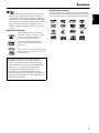
Playable disc formats
This receiver can play the disc types associated with the
logos shown below. (Do not attempt to load any other type
of disc into the receiver, or the receiver may be damaged.)
This product incorporates copyright protection
technology that is protected by method claims of
certain U.S. patents and other intellectual property
rights owned by Macrovision Corporation and other
rights owners. Use of this copyright protection
technology must be authorized by Macrovision
Corporation, and is intended for home and other
limited viewing uses only unless otherwise authorized
by Macrovision Corporation. Reverse engineering or
disassembly is prohibited.
DIGITAL VIDEO
SUPER VIDEO
Features

IMPORTANT SAFETY INSTRUCTIONS
i
* Explanation of Graphical Symbols
1 Read these instructions.
2 Keep these instructions.
3 Heed all warnings.
4 Follow all instructions.
5 Do not use this apparatus near water.
6 Clean only with dry cloth.
7 Do not block any ventilation openings. Install in accordance
with the manufacturer’s instructions.
8 Do not install near any heat sources such as radiators, heat
registers, stoves, or other apparatus (including amplifiers) that
produce heat.
9 Do not defeat the safety purpose of the polarized or
grounding-type plug. A polarized plug has two blades with
one wider than the other. A grounding type plug has two
blades and a third grounding prong. The wide blade or the
third prong are provided for your safety. If the provided plug
does not fit into your outlet, consult an electrician for
replacement of the obsolete outlet.
10 Protect the power cord from being walked on or pinched
particularly at the plugs, convenience receptacles, and the
point where they exit from the apparatus.
11 Only use attachments/accessories specified by the
manufacturer.
12 Use only with the cart, stand, tripod, bracket,
or table specified by the manufacturer, or
sold with the apparatus. When a cart is used,
use caution when moving the cart/apparatus
combination to avoid injury from tip-over.
13 Unplug this apparatus during lightning storms or when unused
for a long periods of time.
14 Refer all servicing to qualified service personnel. Servicing is
required when the apparatus has been damaged in any way,
such as power-supply cord or plug is damaged, liquid has
been spilled or objects have fallen into the apparatus, the
apparatus has been exposed to rain or moisture, does not
operate normally, or has been dropped.
15 Be sure to allow spaces of at least 10 cm above, behind and on
both sides of DVR-S300, and at least 1m above, 30cm behind
and on both sides of NX-SW300 and NX-SW301.
16 Do not place the following objects on this unit:
A vessel with water in it.
If the vessel falls by vibrations and water spills, it may cause
damage to the unit, and/or you may get an electric shock.
Apparatus shall not be exposed to dripping or splashing.
IMPORTANT SAFETY INSTRUCTIONS
IMPORTANT
Please record the serial number of this unit in the
space below.
MODEL:
Serial No.:
The serial number is located on the bottom of
the unit.
Retain this Owner’s Manual in a safe place for
future reference.
CAUTION
RISK OF ELECTRIC SHOCK
DO NOT OPEN
CAUTION: TO REDUCE THE RISK OF
ELECTRIC SHOCK, DO NOT REMOVE
COVER (OR BACK). NO USER-SERVICEABLE
PARTS INSIDE. REFER SERVICING TO
QUALIFIED SERVICE PERSONNEL.
The lightning flash with arrowhead symbol,
within an equilateral triangle, is intended to
alert you to the presence of uninsulated
“dangerous voltage” within the product’s
enclosure that may be of sufficient
magnitude to constitute a risk of electric
shock to persons.
The exclamation point within an equilateral
triangle is intended to alert you to the
presence of important operating and
maintenance (servicing) instructions in the
literature accompanying the appliance.

IMPORTANT SAFETY INSTRUCTIONS
ii
FCC INFORMATION (for US customers)
1 IMPORTANT NOTICE: DO NOT MODIFY THIS UNIT!
This product, when installed as indicated in the instructions contained in this manual, meets FCC requirements.
Modifications not expressly approved by Yamaha may void your authority, granted by the FCC, to use the product.
2 IMPORTANT: When connecting this product to accessories and/or another product use only high quality shielded cables.
Cable/s supplied with this product MUST be used. Follow all installation instructions. Failure to follow instructions could
void your FCC authorization to use this product in the USA.
3 NOTE: This product has been tested and found to comply with the requirements listed in FCC Regulations, Part 15 for Class “B”
digital devices.
Compliance with these requirements provides a reasonable level of assurance that your use of this product in a residential
environment will not result in harmful interference with other electronic devices. This equipment generates/uses radio
frequencies and, if not installed and used according to the instructions found in the users manual, may cause interference harmful
to the operation of other electronic devices. Compliance with FCC regulations does not guarantee that interference will not occur
in all installations. If this product is found to be the source of interference, which can be determined by turning the product
“OFF” and “ON”, please try to eliminate the problem by using one of the following measures:
Relocate either this product or the device that is being affected by the interference.
Utilize power outlets that are on different branch (circuit breaker or fuse) circuits or install AC line filter/s.
In the case of radio or TV interference, relocate/reorient the antenna. If the antenna lead-in is 300 ohm ribbon lead, change the
lead-in to coaxial type cable.
If these corrective measures do not produce satisfactory results, please contact the local retailer authorized to distribute this type
of product. If you can not locate the appropriate retailer, please contact Yamaha Electronics Corp., 6660 Orangethorpe Ave.
Buena Park, CA90622.
The above statements apply ONLY to those products distributed by Yamaha Corporation of America or its subsidiaries.
¶ The name plate is located on the bottom of the unit.
La plaquette signalétique est placée sur le panneau de fond de l’appareil.
LASER SAFETY
This unit employs a laser. Due to possible eye injury,
only a qualified service person should remove the
cover or attempt to service this device.
DANGER
This unit emits visible laser radiation when open. Avoid
direct eye exposure to beam. When this unit is plugged
into a wall outlet, do not place your eyes close to the
opening of the disc tray and other openings or look inside.
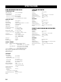
LASER
Type Semiconductor laser GaAlAs
Wave length 650 nm (DVD)
784 nm (VCD/CD)
Output Power 7 mW (DVD/VCD/CD)
Beam divergence 60 degrees
INVISIBLE LASER RADIATION WHEN OPEN
DO NOT STARE INTO BEAM
CAUTION:
INVISIBLE LASER RADIATION WHEN OPEN
AVOID DIRECT EXPOSURE TO THE BEAM
DANGER:
CAUTION
Use of controls or adjustments or performance of
procedures other than those specified herein may result
in hazardous radiation exposure.
SÉCURITÉ LASER
L'appareil utilise un laser. En raison des risques de
blessure des yeux, le retrait du couvercle ou les
réparations de l'appareil devront être confiés
exclusivement à un technicien d'entretien qualifié.
DANGER
Risque d'exposition au laser en cas d'ouverture. Eviter
toute exposition au faisceau. Lorsque cet appareil est
branché à la prise de courant, ne pas approcher les
yeux de l'ouverture du plateau changeur et des autres
ouvertures pour regarder à l'intérieur.
LASER
Type Laser à semi-conducteur
GaAIAs
Longueur d’onde 650 nm (DVD)
784 nm (VCD/CD)
Puissance de sortie 7 mW (DVD/VCD/CD)
Divergence de faisceau 60 degrés
AVERTISSEMENT
L’utilisation de commandes et l’emploi de réglages ou
de méthodes autres que ceux décrits ci-dessous,
peuvent entraîner une exposition à un rayonnement
dangereux.

CAUTION: READ THIS BEFORE OPERATING YOUR UNIT.
iii
1 To assure the finest performance, please read this manual
carefully. Keep it in a safe place for future reference.
2
Install this sound system in a well ventilated, cool, dry, clean place
with at least 10 cm on the top, 10 cm on the left and right, and 10
cm at the back of DVR-S300 and at least 1 m above, 30 cm
behind and on both sides of NX-SW300 or NX-SW301 for
adequate ventilation.
— away from direct sunlight, heat sources,
vibration, dust, moisture, and/or cold.
3 Locate this unit away from other electrical appliances, motors,
or transformers to avoid humming sounds.
4 Do not expose this unit to sudden temperature changes from
cold to hot, nor locate this unit in an environment with high
humidity (i.e., a room with a humidifier) to prevent
condensation inside this unit, which may cause an electrical
shock, fire, damage to this unit, and/or personal injury.
5 Avoid installing this unit in a location where foreign objects
may fall onto this unit or where this unit may be exposed to
liquid dripping or splashing. On the top of this unit, do not
place:
– Other components, as they may cause damage and/or
discoloration on the surface of this unit.
– Burning objects (i.e., candles), as they may cause fire,
damage to this unit, and/or personal injury.
– Containers with liquid in them, as they may fall, spilling
the liquid and causing an electrical shock to the user and/
or damage to this unit.
6 Do not cover this unit with a newspaper, tablecloth, curtain,
etc. in order not to obstruct heat radiation. If the temperature
inside this unit rises, it may cause fire, damage to this unit,
and/or personal injury.
7 Do not plug in this unit to a wall outlet until all connections
are complete.
8 Do not operate this unit upside-down. It may overheat,
possibly causing damage.
9 Do not use excessive force on switches, knobs and/or cords.
10 When disconnecting the power cord from the wall outlet,
grasp the plug; do not pull the cord.
11 Do not clean this unit with chemical solvents; this might
damage the finish. Use a clean, dry cloth.
12 Use only the voltage specified on this unit. Using this unit
with a higher voltage than specified is dangerous and may
cause fire, damage to this unit, and/or personal injury.
YAMAHA will not be held responsible for any damage
resulting from use of this unit with a voltage other than as
specified.
13 To prevent damage by lightning, keep the power cord out and
outdoor antennas disconnected from a wall outlet or the unit
during a lightning storm.
14 Do not attempt to modify or fix this unit. Contact qualified
YAMAHA service personnel when any service is needed. The
cabinet should never be opened for any reason.
15
When not planning to use this unit for long periods of time (i.e.,
vacation), disconnect the AC power plug from the wall outlet.
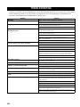
16 Be sure to read the “TROUBLESHOOTING” section on
common operating errors before concluding that this unit is
faulty.
17 Before moving this unit, press STANDBY/ON to set the unit
in standby mode, then disconnect the AC power plug from the
wall outlet.
18 Condensation will form when the surrounding temperature
changes suddenly. Disconnect the power cable from the
outlet, then leave the unit alone.
19 When using the unit for a long time, the unit may become
warm. Turn the power off, then leave the unit alone for
cooling.
20 Install this unit near the AC outlet and where the AC power
plug can be reached easily.
CAUTION: READ THIS BEFORE OPERATING YOUR UNIT.
FOR CANADIAN CUSTOMERS
To prevent electric shock, match wide blade of plug to
wide slot and fully insert.
This Class B digital apparatus complies with Canadian
ICES-003.
This unit is not disconnected from the AC power
source as long as it is connected to the wall outlet,
even if this unit itself is turned off. This state is called
the standby mode. In this state, this unit is designed to
consume a very small quantity of power.
Laser component in this product is capable of emitting
radiation exceeding the limit for Class 1.
WARNING
TO REDUCE THE RISK OF FIRE OR ELECTRIC
SHOCK, DO NOT EXPOSE THIS UNIT TO RAIN
OR MOISTURE.
CAUTION
Danger of explosion if battery is incorrectly replaced.
Replace only with the same or equivalent type.

1
1
2
3
4
5
6
English
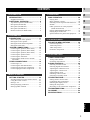
INTRODUCTION ......................................... 2
Supplied accessories........................................ 5
FUNCTIONAL OVERVIEW ......................... 6
Top and front panels (DVR-S300).................. 6
Rear panel (DVR-S300).................................. 7
Rear panel (NX-SW300)................................. 8
Rear panel (NX-SW301)................................. 8
Remote control (For DVR-S300).................... 9
CONNECTIONS ........................................ 11
Roles and layout of the speakers................... 11
Placing the center speaker............................. 12
Placing the front/surround speakers.............. 13
Placing the subwoofer................................... 13
SYSTEM CONNECTIONS........................ 14
Connecting the speakers (DVX-S301).......... 14
Connecting the speakers (DVX-S302).......... 15
Connecting the speakers (DVX-S303).......... 16
Connecting the speaker cables ...................... 17
Connecting the subwoofer............................. 17
Connecting the DVD receiver and the
subwoofer .................................................. 18
OTHER CONNECTIONS........................... 19
Connecting a TV ........................................... 19
Connecting the FM/AM antennas................. 20
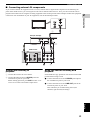
Connecting external AV components ........... 21
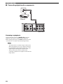
Connecting digital audio components........... 22
GETTING STARTED................................. 23
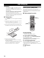
Inserting batteries into the remote control .... 23
Using the remote control............................... 23
Setting a TV .................................................. 24
Setting language preferences......................... 26
Setting speaker channels ............................... 27
DISC OPERATION ................................... 28
Playing discs.................................................. 28
Basic playback controls................................. 28
Selecting various repeat shuffle functions..... 29
Shuffle ........................................................... 29
Other operations for video playback
(DVD/VCD/SVCD)................................... 30
Playing MP3/JPEG/DivX® discs.................. 33
Playing Super Audio CDs ............................. 34
Special features for picture disc playback..... 35
DVD SETUP MENU OPTIONS................. 36
General setup menu ....................................... 36
Audio setup menu.......................................... 38
Video setup menu.......................................... 39
Preference setup menu................................... 41
TUNER OPERATIONS ............................. 44
Tuning radio stations ..................................... 44
Presetting radio stations................................. 44
SOUND CONTROLS ................................ 46
Selecting surround sound .............................. 46
Selecting digital sound effects....................... 46
Adjusting the treble/bass level....................... 46
Adjusting the volume level............................ 47
Night listening mode ..................................... 47
Switching to active mode .............................. 47
Switching to standby mode ........................... 47
OTHER FUNCTIONS................................ 48
Setting remote control codes ......................... 48
Controlling other components....................... 48
Dimming the display screen .......................... 49
Setting the sleep timer ................................... 49
Recording on an external AV component ..... 49
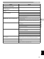
TROUBLESHOOTING.............................. 50
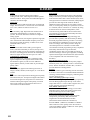
GLOSSARY .............................................. 52
SPECIFICATIONS .................................... 54
CONTENTS
1.INTRODUCTION
2.PREPARATION
3.BASIC OPERATION
4.OPERATIONS
5.ON-SCREEN MENU
6.OTHER FEATURES

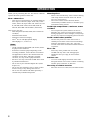
INTRODUCTION
2
Thank you for purchasing this unit. This Owner’s Manual
explains the basic operation of this unit.
Notes about discs
– This receiver is designed for use with the following
discs: Super Audio CD (Super Audio CD), DVD-
Video, Video CD, Super Video CD, Audio CD, CD-
R, CD-RW, DVD-Audio, DVD+RW, DVD+R,
DVD-R, DVD-RW and DVD-RW (VR format).
This receiver can play:
– MP3 and picture (Kodak, JPEG) files recorded on
CD-R(W).
– JPEG/ISO 9660 format
– Maximum 30 character display
–DivX
®
disc on CD-R[W]/DVD+R[W]/
DVD-R[W](3.11, 4.x and 5.x)
– CD-R, CD-RW and DVD-RW (VR format) cannot
be played unless finalized.
– Some discs cannot be played depending on the
recording conditions, such as the PC environment
and application software. The characteristics and
condition of some discs; materials, scratches,
curvature, etc, may result in playback failure.
– Be sure to use only CD-R and CD-RW discs made
by reliable manufacturers.
– Do not use any non-standard shaped discs (heart-
shaped, etc.).
– Do not use discs with tape, seals, or paste on their
surface. Doing so may damage this receiver.
– Do not use discs affixed with labels printed by a
commercially available label printer.
Cleaning discs
– When a disc becomes dirty, clean it with a cleaning
cloth. Wipe the disc from the center out. Do not
wipe in a circlar motion.
– Do not use solvents such as benzine, thinner,
commercially available cleaners, or antistatic spray
intended for analog records.
Avoid high temperatures, moisture, water
and dust
– Do not expose the system, batteries or discs to
humidity, rain, sand or excessive heat (caused by
heating equipment or direct sunlight). Always keep
the disc tray closed to avoid getting dust on the lens.
Avoid condensation problem
– The lens may cloud over when the receiver is
suddenly moved from cold to warm surroundings,
making it impossible to play a disc. Leave the
receiver in the warm environment until the moisture
evaporates.
Disc care
– Write only on the printed side of a CD-R/
CD-RW and only with a soft felt-tipped pen.
– Handle the disc by its edge; do not touch the
surface.
Cabinet care
– Use a soft cloth slightly moistened with a mild
detergent solution. Do not use a solution containing
alcohol, spirits, ammonia, or abrasives.
Choosing a suitable location
– Place the receiver on a flat, hard, and stable surface.
INTRODUCTION
Notes

3
INTRODUCTION
English
INTRODUCTION
1
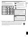
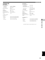
Region codes
The unit is designed to support the Region Management
System. Check the region code number on the disc
package. If the number does not match the unit’s region
number (see the table below or the back of the unit), the
unit may be unable to play the disc.
Sound field features
Manufactured under license from Dolby
Laboratories. “Dolby”, “Pro Logic”, “MLP
Lossless” and the double-D symbol are
trademarks of Dolby Laboratories.
“DTS” and “DTS Digital Surround” are
registered trademarks of Digital Theater
Systems, Inc.
“DivX”, “DivX Certified”, and associated logos
are trademarks of DivXNetworks, Inc and are
used under license.
■ We Want You Listening For A Lifetime
YAMAHA and the Electronic Industries Association’s Consumer Electronics Group want you to get the
most out of your equipment by playing it at a safe level. One that lets the sound come through loud and clear
without annoying blaring or distortion - and, most importantly, without affecting your sensitive hearing.
Since hearing damage from loud sounds is often undetectable until it is too late, YAMAHA and the
Electronic Industries Association’s Consumer Electronics Group recommend you to avoid prolonged
exposure from excessive volume levels.
Destination
Region
code of
DVR-S300
Playable
discs
U.S.A. and
Canada models
U.K. and Europe
models
Australia
model
Korea, Asia and
Taiwan models
1 1
ALL
2 2
ALL
4 4
ALL
3 3
ALL
This product incorporates copyright protection
technology that is protected by method claims of
certain U.S. patents and other intellectual property
rights owned by Macrovision Corporation and other
rights owners. Use of this copyright protection
technology must be authorized by Macrovision
Corporation, and is intended for home and other
limited viewing uses only unless otherwise authorized
by Macrovision Corporation. Reverse engineering or
disassembly is prohibited.
Active Servo Processing Subwoofer System with built-in
power amplifier.
This subwoofer system (NX-SW300, NX-SW301) employes
Advanced YAMAHA Active Servo Technology which
YAMAHA has developed for reproducing higher quality
super-bass sound. This super-bass sound adds a more
realistic, theater-in-the-home effect to your stereo syetem.

4
INTRODUCTION
DVX-S301 DVX-S302
DVD receiver
(DVR-S300)
Subwoofer
(NX-SW301)
Center speaker
(NX-C301)
Front/Surround
speakers (x4)
(NX-S301)
DVD receiver
(DVR-S300)
Subwoofer
(NX-SW301)
Center speaker
(NX-C302)
Front/Surround
speakers (x4)
(NX-S302)

5
INTRODUCTION
English
INTRODUCTION
1
DVX-S303
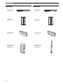
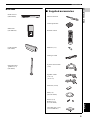
■ Supplied accessories
DVD receiver
(DVR-S300)
Subwoofer
(NX-SW300)
Center speaker
(NX-C302)
Front/Surround
speakers (x 4)
(NX-S302)
TV VOL TV CH
EFFECT SURR
VOL
TRE
MENU
SET UP
PRESET
SUBTITLE AUDIO ANGLE ZOOM
TV AUX TUNER DVD/CD
TV
INPUT
MUTE
BASS
ENTER
TOP MENU/RETURN
ON SCREEN
PROG
REPEAT A - B
SHUFFLE
SCAN
PAGE
DIMMER
POWER
POWER
SLEEP
NIGHT
TV
System control cable
(4 m )
FM wire antenna
Video pin cable
Remote control
AM loop antenna
Speaker cables
(5 m x 3)
(15 m x 2)
Fasteners (2 sets)
Batteries (x 2)
Base(x 4)
(For NX-S302)
Screws (x 8)
Washers (x 8)
(For NX-S302)
Non-skid pad (1 set)
(For NX-SW301)

FUNCTIONAL OVERVIEW
6
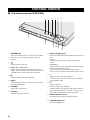
■ Top and front panels (DVR-S300)
1 STANDBY/ON
Turns on the DVD receiver, or sets it to the standby
mode (see “Auto eco power standby mode” on
page 28).
2
Opens/closes the disc tray.
3 b / a , w / f
DVD/CD mode: selects the previous/next track or
chapter. Press and hold to fast forward or fast reverse.
TUNER mode: tunes the radio preset up/down.
4 e
DVD/CD mode: pauses disc playback.
5 INPUT
Selects and input source or sets the priority level for
the audio input signals.
6 VOLUME
Adjusts the volume level.
7 Disc tray
Load the disc in the disc tray.
8 System display panel
Shows information about the operational status of the
unit.
MULTI
Lights up when you play a multi-channel audio
source.
DOWNMIX
Lights up when you play discs that allow down mixing
of multi-channel audio sources.
It does not light up for discs that prohibit down
mixing, even if you play a multi-channel audio source.
9 h
DVD/CD mode: starts disc playback.
TUNER mode: starts preset radio station installation
in Plug & Play mode.
0 s
Exits an operation.
DVD/CD mode: stops playback.
TUNER mode: erases a preset radio station in Preset
mode if held more than two seconds, or stops preset
radio station installation in Auto Preset mode.
A Remote control sensor
Point the remote control towards this sensor.
B Head phone jack
Connects headphones.
FUNCTIONAL OVERVIEW
654321
B
A
0
9
8
7

FUNCTIONAL OVERVIEW
7
INTRODUCTION
1
English
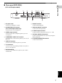
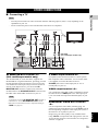
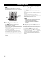
■ Rear panel (DVR-S300)
(U.K. and Europe models)
1 AC power cord
Connect to a standard AC outlet.
2 AV MONITOR OUT terminal
(U.K. and Europe models only)
Connect to your TV (see page 19).
3 VIDEO output terminal
Connect to the video (composite) jack on your TV
(see page 19).
4 COMPONENT VIDEO OUT terminal
Connect the the Y P
B/CB PR/CR jacks on your TV (see
page 19).
5 LINE OUT terminal
Connect to the AUDIO IN jacks on your VCR.
6 TV IN terminal
Connect to the corresponding AUDIO OUT jacks on
your TV (see page 19).
7 AUX IN terminal
Connect to the AUDIO OUT jacks on your VCR or
cassette deck.
8 FM ANT terminal
Connect the FM antenna.
9 GND and AM ANT terminals
Connect the AM loop antenna.
0 S VIDEO output terminal
Connect to the S-video jack on your TV or VCR.
A OPTICAL DIGITAL IN terminal
Connect to the DIGITAL OUT jack on your digital
audio component.
B SYSTEM CONNECTOR terminal
Connect the subwoofer.
SYSTEM
CONNECTOR
AUX INTV INLINE OUT
S VIDEO
AV MONITOR OUT
(DVD ONLY)
VIDEO
OPTICAL
COMPONENT
Y
P
R PB
PCM/DTS
q
DIGITAL
DIGITAL INVIDEO OUT (DVD ONLY)
FM
ANT
AM
ANT
GND
TO SUBWOOFER
75Ω UNBAL
L
R
9821 4 5 6 73
B0A

FUNCTIONAL OVERVIEW
8
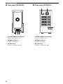
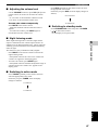
■ Rear panel (NX-SW300)
1 SYSTEM CONNECTOR terminal
Connect to the DVD receiver.
2 SPEAKER terminals
Connect to the speakers.
3 AC power cord
Connect to a standard AC outlet.
■ Rear panel (NX-SW301)
1 SYSTEM CONNECTOR terminal
Connect to the DVD receiver.
2 SPEAKER terminals
Connect to the speakers.
3 AC power cord
Connect to a standard AC outlet.
1 23
12
3

FUNCTIONAL OVERVIEW
9
INTRODUCTION
1
English
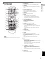
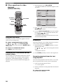
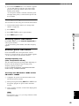
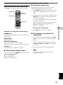
■ Remote control
(For DVR-S300)
For details on how to use the remote control, see page 23.
1 POWER (TV)
Turns on the TV, or sets it to the standby mode.
2 DIMMER
Selects different levels of brightness for the display
panel.
3 Numeric keypad (0 – 9)
Enters a track/title number of the disc.
Enters a number of a preset radio station.
4 REPEAT
Selects various repeat modes.
5 PROG
DVD/CD mode: starts programming.
TUNER mode: starts automatic/manual preset
programming if held for more than two seconds.
6 TOP MENU/RETURN
Returns to the previous menu.
Displays the top-level disc menu
(if available).
7 Cursors ( / / / )
Selects movement direction in the menu.
TUNER mode: press left or right to tune the radio
frequency.
TUNER mode: press up or down to select auto
tuning.
8 ENTER (OK)
Confirms a selection.
9 MENU
Enters or exits the disc contents menu.
For VCD version 2.0 only:
In stop mode, turns on/off playback control (PBC)
mode.
During playback, returns to the main menu.
0 s
Exits an operation.
DVD/CD mode: stops playback.
DVD/CD mode: holding down the button will open
and close the disc tray.
TUNER mode: erases a preset radio station if held
for more than two seconds.
A d PRESET u ( b / a )
DVD/CD mode: selects the previous/next track or
chapter. Press and hold to fast forward or fast
reverse.
TUNER mode: press to select a preset radio station.
B SUBTITLE
Selects a subtitle language.
Note
TV VOL TV CH
EFFECT SURR
VOL
TRE
MENU
SET UP
PRESET
SUBTITLE AUDIO ANGLE ZOOM
TV AUX TUNER DVD/CD
TV
INPUT
MUTE
BASS
ENTER
TOP MENU/RETURN
ON SCREEN
PROG
REPEAT A - B
SHUFFLE
SCAN
PAG E
DIMMER
POWER
POWER
SLEEP
NIGHT
TV
P
Q
R
S
t
U
V
W
X
Y
7
8
9
0
A
B
C
D
E
F
G
H
1
2
3
4
5
6
I
J
K
L
N
O
M

FUNCTIONAL OVERVIEW
10
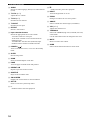
C AUDIO
Selects an audio language (DVD) or an audio channel
(VCD).
D TV VOL (+ / –)
Adjusts the TV volume.
E TV CH (+ / –)
Switches the TV channel.
F TV INPUT
Switches the TV input.
G EFFECT
Selects a sound effect.
H Input selection buttons
Selects the appropriate active source mode.
TV mode: switches to TV input.
AUX mode: switches to AUX ANALOG/AUX
DIGITAL input.
TUNER mode: switches tuner (FM/AM) input.
DVD/CD mode: switches to DVD/CD mode.
I POWER ( )
Turns on the DVD receiver, or sets it to the standby
mode.
J SLEEP
Sets the sleep timer.
K SCAN
Scans each track/chapter on the disc.
L PAGE
Turns the pages of DVD-Audio still pictures.
M REPEAT A-B
Repeats a specific section on a disc.
N SHUFFLE
Plays tracks in random order.
O ON SCREEN
Displays the current status or disc information.
P SET UP
Enters or exits the system setup menu.
Q h
DVD/CD mode: starts disc playback.
R e
DVD/CD mode: pauses disc playback.
S NIGHT
Turns the Night mode on or off.
T ZOOM
Enlarges or reduces the TV screen picture.
U ANGLE
Selects a DVD disc camera angle (if available).
V VOL (+ / –)
Adjusts the volume level.
W TRE/BASS
Selects the TREBLE (high tone) or BASS (low tone)
sound mode.
Use the VOLUME control to change the tone level.
X MUTE
Mutes or restores the volume.
Y SURR
Selects multi-channel surround or stereo mode.

CONNECTIONS
11
English
PREPARATION
2
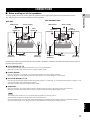
■ Roles and layout of the speakers
To enjoy quality sounds you need to place the speakers in their appropriate positions and install them correctly.
The following show the recommended layout of the speakers.
For the best possible surround sound, all of the speakers (except the subwoofer) should be placed at the same distance
from the listening position.
1 Front Speakers (L, R)
Place the front left/right speakers on both sides of your TV at equal distances.
Main roles: Produces front channel (stereo) sounds and effect sounds.
2 Center Speaker
Place on top of the TV or inside the TV rack so that the speaker and TV are aligned vertically.
Main role: Produces sounds oriented toward the center of the screen such as dialogues or vocal sounds.
3 Surround Speakers (L, R)
Place the surround left/right speakers behind the listening position. (For NX-S301, we recommend placing them at a height of 1.8 m
(6 feet) and pointing them at the listening position.)
Main roles: Produces surround sounds and effect sounds.
4 Subwoofer
Place the subwoofer near a front speaker and turn it slightly toward the center of the room to reduce wall reflections.
Main roles: Produces bass sounds and low frequency (LFE) sounds contained in Dolby Digital or DTS.
To avoid magnetic interference, do not position the front speakers too close to your TV.
Allow adequate ventilation around the DVD receiver and subwoofer.
Bass sounds produced by the subwoofer may be heard differently depending on the listening position and subwoofer location.
To enjoy desired sounds, try to change the location of the subwoofer according to the listening position.
CONNECTIONS
1
1
2
3
4
3
+
–
+
–
DVD receiver
Center speaker
Front
speaker (R)
Surround
speaker (L)
Subwoofer
Surround
speaker (R)
Front
speaker (L)
DVX-S301
1
1
2
4
3
3
DVD receiver Center speaker
Front
speaker (R)
Subwoofer
Front
speaker (L)
Surround
speaker (R)
Surround
speaker (L)
DVX-S302/DVX-S303
Note

CONNECTIONS
12
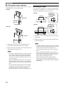
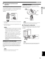
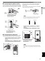
■ Placing the center speaker
When placing the center speaker on top of the TV, use the
supplied fasteners to secure the speaker.
1 Peel off the seals on one side of the fasteners and
attach them to the bottom of the center speaker.
2 Peel off the seals on the other side of the fasteners and
attach them to the top of the TV.
– Do not place the speaker on the TV if the top of the
TV is uneven or narrower than the bottom surface
of the speaker. Doing so may cause the speaker to
fall. In this case, place the speaker inside a TV rack
or on a level floor.
– Before attaching the fasteners to the TV, clean the
surface with a dry cloth. A dirty or wet surface may
weaken the adhesive force and cause the speaker to
fall.
– Do not touch the bonding surfaces of the fasteners
after peeling off the seals. Doing so may weaken
the adhensive force and cause the speaker to
fall.this installation. Use metric screw threads only.
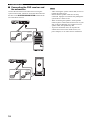
Attaching to a wall
You can attach the speakers to a wall using commercially
available screws (Diameter: 3.5 to 4 mm, Length: 25 mm
or more). Each speaker requires two screws.
1 Install two screws in the wall where you want to place
the speaker.
2 Hang the speaker on the screws using the holes in the
back of the speaker.
– To attach a speaker to a wall using screws, the wall
must be firm. Do not attach a speaker to a wall that
is made of weak materials such as plaster or
veneered woods. Doing so may cause the speaker
to fall.
– When connectiong the speakers, fix the speaker
cables in place so that cables do not loosen. If your
foot or hand accidentally gets caught on a loose
speaker cable, the speaker may fall.
– After attaching each speaker, check that the
speaker is fixed securely. YAMAHA will bear no
reponsibility for any accidents caused by improper
installations.
Notes
Fastener
Peel off
the seal
NX-C301
Fastener
Peel off
the seal
NX-C302
Notes
+
–
5 mm
Screws (3.5
to 4 mm dia.,
commercially
available)
20 mm or more
110 mm
NX-C301
+
–
5 mm
Screws (3.5
to 4 mm dia.,
commercially
available)
20 mm or more
151 mm
NX-C302

CONNECTIONS
13
English
PREPARATION
2
■ Placing the front/surround
speakers
Attaching to a wall
You can attach the speakers to a wall using commercially
available screws (Diameter: 3.5 to 4 mm, Length: 25 mm
or more). Each speaker requires two screws.
1 Install two screws in the wall where you want to place
the speaker.
2 Hang the speaker on the screws using the holes in the
back of the speaker.
– To attach a speaker to a wall using screws, the wall
must be firm. Do not attach a speaker to a wall that
is made of weak materials such as plaster or
veneered woods. Doing so may cause the speaker
to fall.
– When connectiong the speakers, fix the speaker
cables in place so that cables do not loosen. If your
foot or hand accidentally gets caught on a loose
speaker cable, the speaker may fall.
– After attaching each speaker, check that the
speaker is fixed securely. YAMAHA will bear no
reponsibility for any accidents caused by improper
installations.
Hanging on a wall (NX-S301)
You can hang the speakers on a wall using a commercially
available bracket and screws (Diameter: 6 mm). Attach a
bracket firmly to the rear of the speakers using screws.
Then mount a screw on the wall where the speaker is to be
hung and hook the speaker securely onto the mounted
screws.
Do not use screw threads neasured in inches for this
installation. Use metric screw threads only.
Attaching the base
Attach the base to the bottom of the front/surround
speakers (NX-S302) with the supplied base mounting
screws as shown below.
Placing the speakers (NX-S302) on the places such as hard
wooden floor may scratch the surface of the floor.
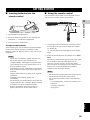
■ Placing the subwoofer
Attach the non-skid pads to the bottom of the subwoofer
(NX-SW301), and then place the subwoofer on a level
hard floor.
Using non-skid pads prevents the subwoofer from sliding
when it vibrates, and ensure quality sound production.
Notes
Note
+
–
5 mm
Screws (3.5
to 4 mm dia.,
commercially
available)
20 mm or more
40 mm
NX-S301
Note
Note
Base
mounting
screws
NX-S302
Base
Washer
Peel off
the seal

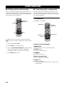
SYSTEM CONNECTIONS
14
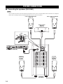
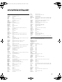
■ Connecting the speakers (DVX-S301)
– Do not connect the power cord of the subwoofer and DVD receiver into an AC outlet until all cable connections are completed.
– Please refer to the pages below for detailed information on how connect each speaker.
SYSTEM CONNECTIONS
Notes
SYSTEM
CONNECTOR
TO SUBWOOFER
L
R
+
–
+
–
+
–
+
–
+
–
Front speaker (R)NX-S301
(page 17)
Surround
speaker (R)
NX-S301
(page 17)
Center speaker
NX-C301
(page 17)
Subwoofer
(NX-SW301)
DVD receiver (DVR-S300)
Front speaker (L) NX-S301
(page 17)
Surround
speaker (L)
NX-S301
(page 17)
Tab
Red
Green
Tab
Gray
White
Blue

SYSTEM CONNECTIONS
15
English
PREPARATION
2
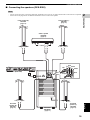
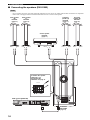
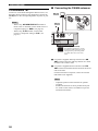
■ Connecting the speakers (DVX-S302)
– Do not connect the power cord of the subwoofer and DVD receiver into an AC outlet until all cable connections are completed.
– Please refer to the pages below for detailed information on how connect each speaker.
Notes
SYSTEM
CONNECTOR
TO SUBWOOFER
L
R
+
+
+
+
+
+
+
+
Front speaker (R)
NX-S302
(page 17)
Surround
speaker (R)
NX-S302
(page 17)
Center speaker
NX-C302
(page 17)
Subwoofer
NX-SW301
(page 17)
DVD receiver (DVR-S300)
Front speaker (L)
NX-S302
(page 17)
Surround
speaker (L)
NX-S302
(page 17)
Tab
Red
Green
Tab
Gray
White
Blue
Black
Red
Black
Red
Red
Red
Red
Black
Black
Black
A página está carregando...
A página está carregando...
A página está carregando...
A página está carregando...
A página está carregando...
A página está carregando...
A página está carregando...
A página está carregando...
A página está carregando...
A página está carregando...
A página está carregando...
A página está carregando...
A página está carregando...
A página está carregando...
A página está carregando...
A página está carregando...
A página está carregando...
A página está carregando...
A página está carregando...
A página está carregando...
A página está carregando...
A página está carregando...
A página está carregando...
A página está carregando...
A página está carregando...
A página está carregando...
A página está carregando...
A página está carregando...
A página está carregando...
A página está carregando...
A página está carregando...
A página está carregando...
A página está carregando...
A página está carregando...
A página está carregando...
A página está carregando...
A página está carregando...
A página está carregando...
A página está carregando...
A página está carregando...
A página está carregando...
A página está carregando...
A página está carregando...
A página está carregando...
A página está carregando...
-
 1
1
-
 2
2
-
 3
3
-
 4
4
-
 5
5
-
 6
6
-
 7
7
-
 8
8
-
 9
9
-
 10
10
-
 11
11
-
 12
12
-
 13
13
-
 14
14
-
 15
15
-
 16
16
-
 17
17
-
 18
18
-
 19
19
-
 20
20
-
 21
21
-
 22
22
-
 23
23
-
 24
24
-
 25
25
-
 26
26
-
 27
27
-
 28
28
-
 29
29
-
 30
30
-
 31
31
-
 32
32
-
 33
33
-
 34
34
-
 35
35
-
 36
36
-
 37
37
-
 38
38
-
 39
39
-
 40
40
-
 41
41
-
 42
42
-
 43
43
-
 44
44
-
 45
45
-
 46
46
-
 47
47
-
 48
48
-
 49
49
-
 50
50
-
 51
51
-
 52
52
-
 53
53
-
 54
54
-
 55
55
-
 56
56
-
 57
57
-
 58
58
-
 59
59
-
 60
60
-
 61
61
-
 62
62
-
 63
63
-
 64
64
-
 65
65


Yamaha DVX-S301 Manual do usuário
- Categoria
- Leitores de DVD
- Tipo
- Manual do usuário
em outras línguas
- español: Yamaha DVX-S301 Manual de usuario
- français: Yamaha DVX-S301 Manuel utilisateur
- italiano: Yamaha DVX-S301 Manuale utente
- English: Yamaha DVX-S301 User manual
- русский: Yamaha DVX-S301 Руководство пользователя
- Nederlands: Yamaha DVX-S301 Handleiding
- Deutsch: Yamaha DVX-S301 Benutzerhandbuch
- dansk: Yamaha DVX-S301 Brugermanual
- čeština: Yamaha DVX-S301 Uživatelský manuál
- svenska: Yamaha DVX-S301 Användarmanual
- polski: Yamaha DVX-S301 Instrukcja obsługi
- Türkçe: Yamaha DVX-S301 Kullanım kılavuzu
- suomi: Yamaha DVX-S301 Ohjekirja
- română: Yamaha DVX-S301 Manual de utilizare
Artigos relacionados
-
Yamaha DVD-S530 Manual do proprietário
-
-
-
-
-
-
Yamaha BD-A1010 Manual do proprietário
-
-
Yamaha DVD-S550 Manual do proprietário
-
Outros documentos
-
LG DV286-E3M Manual do usuário
-
LG DVX276 Manual do usuário
-
Philips HTS2500/55 Manual do usuário
-
Philips PET704/58 Manual do usuário
-
-
Roland CM-110 Manual do usuário
-
-
TEAC MC-DX20B Manual do proprietário
-
-
JVC XV-S332SL Manual do usuário