
O P E R A T I N G I N S T R U C T I O N S
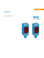
WSE4F
Miniature photoelectric sensors


Described product
W4F
WSE4F
Manufacturer
SICK AG
Erwin-Sick-Str. 1
79183 Waldkirch
Germany
Legal information
This work is protected by copyright. Any rights derived from the copyright shall be
reserved for SICK AG. Reproduction of this document or parts of this document is
only permissible within the limits of the legal determination of Copyright Law. Any modi‐
fication, abridgment or translation of this document is prohibited without the express
written permission of SICK AG.
The trademarks stated in this document are the property of their respective owner.
© SICK AG. All rights reserved.
Original document
This document is an original document of SICK AG.
2006/42/EC
NO
SAFETY
8025304 / 2021-05-12 | SICK
Subject to change without notice
3

Contents
1 General safety notes......................................................................... 5
2 Notes on UL approval........................................................................ 5
3 Product description........................................................................... 5
3.1 Intended use............................................................................................. 5
3.2 Operating elements and status indicators.............................................. 5
4 Mounting............................................................................................. 6
5 Electrical installation........................................................................ 6
6 Additional functions.......................................................................... 8
7 Commissioning.................................................................................. 9
7.1 Alignment.................................................................................................. 9
7.2 Check the application conditions:........................................................... 10
7.3 Setting....................................................................................................... 11
7.4 Process data structure............................................................................. 12
8 Troubleshooting................................................................................. 12
9 Disassembly and disposal............................................................... 13
10 Maintenance...................................................................................... 13
11 Technical specifications................................................................... 14
11.1 Dimensional drawings.............................................................................. 15
CONTENTS
4
8025304 / 2021-05-12 | SICK
Subject to change without notice

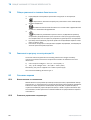
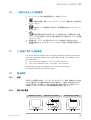
1 General safety notes
■
Read the operating instructions before commissioning.
■
Connection, mounting, and configuration may only be performed by trained
specialists.
■
2006/42/EC
NO
SAFETY
Not a safety component in accordance with the EU Machinery Directive.
■
Do not install the sensor at locations that are exposed to direct UV radiation
(sunlight) or other weather influences, unless this is expressly permitted in the
operating instructions.
■
When commissioning, protect the device from moisture and contamination.
■
These operating instructions contain information required during the life cycle of
the sensor.
2 Notes on UL approval
The device shall be supplied from an isolating transformer having a secondary overcur‐
rent protective device that complies with UL 248 to be installed in the field rated either:
a) max 5 amps for voltages 0 ~ 20 V (0 ~ 28.3 V peak), or
b) 100 / Vp for voltages of 20 ~ 30 V (28.3 ~ 42.4 V peak).
Alternatively, they can be supplied from a Class 2 power supply.
UL Environmental Rating: Enclosure type 1
3 Product description
3.1 Intended use
The WSE4F is an opto-electronic through-beam photoelectric sensor (referred to as
“sensor” in the following) for the optical, non-contact detection of objects, animals, and
persons. A sender (WS) and a receiver (WE) are required for operation. If the product is
used for any other purpose or modified in any way, any warranty claim against SICK AG
shall become void.
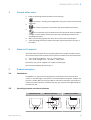
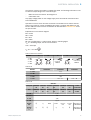
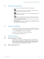
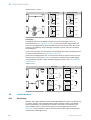
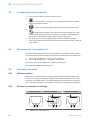
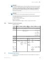
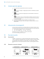
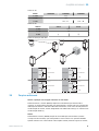
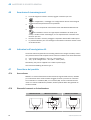
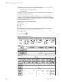
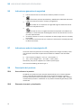
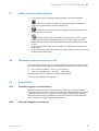
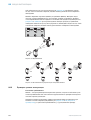
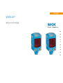
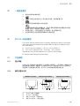
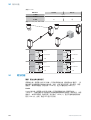
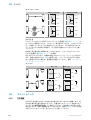
3.2 Operating elements and status indicators
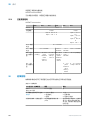
WSO4Fx-xxxxxxA0 WEO4Fx-xxxxxx30A00 WEO4Fx-xxxxxx00A00
4 3
1
2
4 3
1
4 3
GENERAL SAFETY NOTES 1
8025304 / 2021-05-12 | SICK
Subject to change without notice
5

1
BluePilot blue: alignment aid
2
Teach-Button: adjusting the sensitivity
3
LED indicator yellow: status of received light beam
4
LED indicator green: supply voltage active
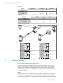
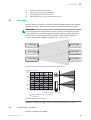
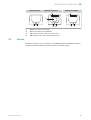
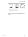
4 Mounting
Mount sensors (sender and receiver) using suitable mounting brackets (see the SICK
range of accessories). Align the sender and receiver with each other.
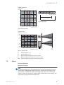
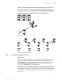
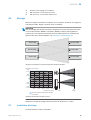
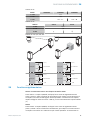
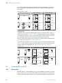
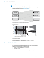
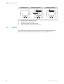
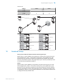
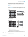
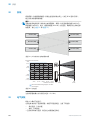
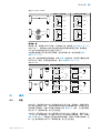
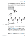
NOTE
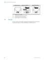
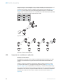
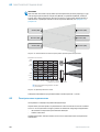
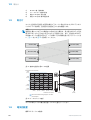
When mounting multiple through-beam photoelectric sensors next each other, swap
the arrangement of the sender (WSO4F) and receiver (WEO4F) for every second pair.
Also maintain a sufficiently large distance between the pairs based on the light spot
diameter of the sender (WSO4F). See figure 1 and figure 2.
Receiver (WE)
Receiver (WE)
Sender (WS)
Sender (WS)
Sender (WS)
Receiver (WE)
Figure 1: Arrangement of multiple through-beam photoelectric sensors
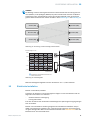
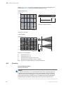
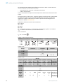
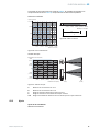
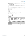
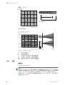
0
Distance in m (feet)
Dimensions in mm (inch)
100
(3.94)
200
(7.87)
–200
(–7.87)
–100
(–3.94)
0
2
(6.56)
6
(19.69)
8
(26.25)
4
(13.12)
10
(32.81)
10
(32.81)
1
(3.28)
Recommended sensing range for the best
performance
Figure 2: Light beam diameter
Note the sensor’s maximum permissible tightening torque of < 0,4 Nm.
5
Electrical installation
Operation in standard I/O mode:
4 MOUNTING
6
8025304 / 2021-05-12 | SICK
Subject to change without notice

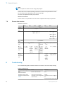
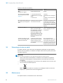
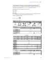
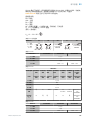
The sensors must be connected in a voltage-free state. The following information must
be observed, depending on the connection type:
– Male connector connection: Pin assignment
– Cable: Wire color
Only apply voltage/switch on the voltage supply once all electrical connections have
been established.
Operation in IO-Link mode: Connect the device to a suitable IO-Link master and inte‐
grate in the master or control via IODD/function block. The green LED flashes on the
sensor. IODD and function block are available to download from www.sick.com under
the part number.
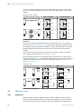
Explanations on connection diagram.
BN = brown
WH = white
BU = blue
BK = black
MF (pin 2 configuration) = external input, teach-in, switching signal
Q
L1
/C = switching output, IO-Link communication
Test = Test input
U
B
: 10 ... 30 V DC
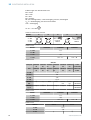
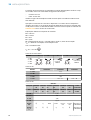
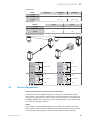
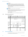
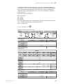
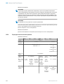
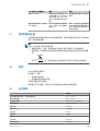
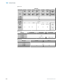
Table 1: Electrical connection
WSE4Fx- x4 x2 xH x1 -xG
1 = BN
2 = WH
3 = BU
4 = BK
1
2
4 3
2
1
4
3
0.14 mm
2
AWG26
1
4
3
0.14 mm
2
AWG26
Table 2: DC
WSO4Fx- xx1ZZxZZZ xx2ZZxZZZ Xx3ZZxZZZ
1 = BN + (L+)
2 = WH -
3 = BU - (M)
4 = BK Test → L+ Test → M
Table 3: DC
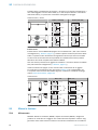
WEO4Fx-
Push-pull xx162xxA
00
xx161xxA
00
xx163xxA
00
xx165xxA
00
xx16AxxA
00
xx16NxxA
00
xx16x
xxxA01-A99
PNP xx862xxA
00
xx861xxA
00
xx863xxA
00
xx865xxA
00
xx86AxxA
00
xx86NxxA
00
xx86xxxxA0
1-A99
1 = BN + (L+)
2 = WH MF
3 = BU - (M)
4 = BK Q
L1
/C
Default:
MF
Q
Q Alarm Alarm no func‐
tion
no func‐
tion
www.sick.co
m 8025304
Default:
Q
L1
/C
Q
Q Q
Q Q
Q
www.sick.co
m 8025304
ELECTRICAL INSTALLATION 5
8025304 / 2021-05-12 | SICK
Subject to change without notice
7

Table 4: DC
WSO4F- xx1ZZxZZZ xx2ZZxZZZ Xx3ZZxZZZ
1 = BN + (L+)
3 = BU - (M)
4 = BK Test → L+ Test → M
Table 5: DC
WEO4Fx- xx312x xx311x
1 = BN + (L+)
3 = BU - (M)
4 = BK Q
Q
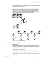
Table 6: Push-pull, PNP, NPN
Push-pull
PNP
NPN
+ (L+)
Q ≤ 100 mA
‒ (M)
Push-pull
PNP
NPN
+ (L+)
Q ≤ 100 mA
‒ (M)
Push-pull
PNP
NPN
+ (L+)
Q ≤ 100 mA
‒ (M)
Push-pull
PNP
NPN
+ (L+)
Q ≤ 100 mA
‒ (M)
6 Additional functions
Alarm: Operation with borderline light reception
Alarm output: The sensor (WSE4F) features a pre-failure notification output (“Alarm”
in the connection diagram), which issues a notification if the sensor is only ready for
operation to a limited extent. The LED flashes in this case. Possible causes: Sensor
is contaminated, sensor is out of alignment. In the good state: LOW (0), if excessively
contaminated HIGH (1).
Health
Health output: The sensor (WSE4F) features a pre-failure notification output (“Health”
in the connection diagram), which issues a notification if the sensor is only ready for
operation to a limited extent or the cable has been interrupted. Possible causes: Sensor
6 ADDITIONAL FUNCTIONS
8
8025304 / 2021-05-12 | SICK
Subject to change without notice

is contaminated, sensor is out of alignment, cable is damaged. In the good state: HIGH
(1), if excessively contaminated or in the event of cable interruption LOW (0). The yellow
LED indicator flashes in this case.
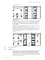
Table 7: Alarm / Health
Alarm (≤ 100 mA) Health (≤100 mA)
+ (L+)
Alarm
‒ (M)
+ (L+)
Health
‒ (M)
+ (L+)
Alarm
‒ (M)
+ (L+)
Health
‒ (M)
Test input
Test input: The WSE4F sensors feature a test input (“Test” on the connection diagram
[see table 2, page 7]), which can be used to switch the sender off and, therefore, check
that the sensor is functioning correctly: If female cable connectors with LED indicators
are used, you must ensure that the TI is assigned accordingly.
It is important that there is no object between the sender and receiver, activate the test
input (see the connection diagram [see table 2, page 7]).
The send LED is shut down or the detection of an object is simulated. Refer to table 8
to check the function. If the switching output fails to behave in accordance with the
following table, check the application conditions, see "Troubleshooting", page 12.
Table 8: Test
Test → M Test → L+
+ (L+)
Test
‒ (M)
+ (L+)
Test
– (M)
+ (L+)
Test
‒ (M)
+ (L+)
Test
– (M)
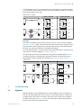
7 Commissioning
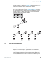
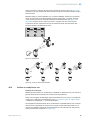
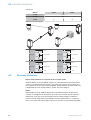
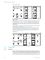
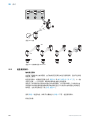
7.1 Alignment
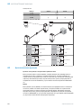
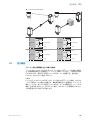
WSO4FP: Align the sender (WSO4F) with the receiver (WEO4F). Select the position so
that the red emitted light beam hits the receiver. Tip: Use white paper or a reflector as
an alignment aid. The sender must have a clear view of the receiver, with no object in
the path of the beam [see figure 3]. You must ensure that the optical openings (front
screen) of the sensors are completely clear.
ADDITIONAL FUNCTIONS 6
8025304 / 2021-05-12 | SICK
Subject to change without notice
9

WSO4FI: Align the sender (WSO4F) with the receiver (WEO4F). Select the position so
that the infrared light (not visible) hits the receiver. The correct alignment can only be
detected via the LEDs. See figure 3 and table 6. The sender must have a clear view of
the receiver, with no object in the path of the beam. You must ensure that the optical
openings (front screen) of the sensors are completely clear.
Figure 3: Alignment
WEO
WEO
WSO
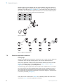
Figure 4: Alignment aid BluePilot
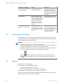
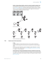
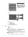
7.2
Check the application conditions:
Sensing range
WSE4F are through-beam photoelectric sensors that can be used at shorter distances,
in particular due to the large sensing range or the very high operating reserve.
Observe the application conditions: Adjust the distance between the sender and the
receiver according to the corresponding diagram [see figure 6 and see figure 5,
page 11] (x = sensing range, y = operating reserve).
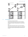
If several through-beam photoelectric sensors which are installed next to one another
are to be used, we recommend swapping the sender/receiver arrangement at every
second through-beam photoelectric sensor and ensuring that there is sufficient dis‐
tance between the through-beam photoelectric sensors. By doing this, mutual interfer‐
ence can be prevented [see figure 1].
Check the function as described in table 6. If the switching output fails to behave as
described in table 6, check the application conditions.
7 COMMISSIONING
10
8025304 / 2021-05-12 | SICK
Subject to change without notice

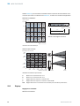
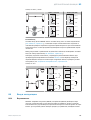
Standard reflectors:
0
Operating reserve
Distance in m (feet)
2
(6.56)
6
(19.69)
8
(26.25)
4
(13.12)
10
(32.81)
1
100
10
1,000
10,000
Figure 5: Characteristics
0
7.5 10
0
Distance in m (feet)
2
(6.56)
6
(19.69)
8
(26.25)
4
(13.12)
10
(32.81)
D
A
B
C
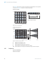
Figure 6: Bar graph
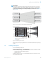
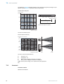
Light spot size:
0
Distance in m (feet)
Dimensions in mm (inch)
100
(3.94)
200
(7.87)
–200
(–7.87)
–100
(–3.94)
0
2
(6.56)
6
(19.69)
8
(26.25)
4
(13.12)
10
(32.81)
10
(32.81)
1
(3.28)
Figure 7: Light spot size
A Sensing range min. in m
B Sensing range max. in m
C Maximum distance range from receiver to sender
D Recommended distance range from receiver to sender
blue Recommended sensing range for the best performance
7.3 Setting
Sensitivity adjustment
WEO4Fx-xxxxxx30A00:
NOTE
For some applications (e.g., when switching errors arise due to reflections), we recom‐
mend slightly misaligning the sender and receiver or significantly reducing the oper‐
ating reserve. The WSE4F can suppress switching errors under these conditions by
means of a teach-in (via IO-Link or using the Teach-in pushbutton on the housing). This
reduces the operating reserve at the same time.
COMMISSIONING 7
8025304 / 2021-05-12 | SICK
Subject to change without notice
11

NOTE
Do not operate the teach-in button using sharp objects.
Please refer to the enclosed operating instructions for the IO-Link photoelectric sensor
for information about adjusting the IO-Link sensing range.
The sensor is adjusted and ready for operation.
WEO4Fx-xxxxxx00A00:
Sensor which it is not possible to set: the sensor is adjusted and ready for operation.
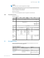
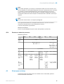
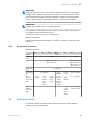
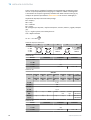
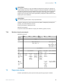
7.4 Process data structure
WSE4FP-xxxxxxxxAxx:
A00 A70 A71 A72 A73 A75
IO-Link V1.1
Process
data
2 bytes 4 bytes
Byte 0: bits 15... 8
Byte 1: bits 7... 0
Byte 0: bits 31...
24
Byte 1: bits 13...
16
Byte 2: bits 15...
8
Byte 3: bits 7... 0
Bit 0 / Data
type
Q
L1
/ Boolean
Bit 1 / Data
type
Q
L2
/ Boolean Qint.1 /
Boolean
Q
L2
/ Boo‐
lean
Qint.1 / Boolean
Bit... /
Descrip‐
tion / Data
type
2 ...15 /
[empty]
2 ...15 /
[time
measure‐
ment
value] /
UInt 14
2 … 15 /
[counter
value] /
UInt 14
2 … 15 /
[length /
speed
measure‐
ment] /
SInt14
2 /
Qint.1 /
Boolean
2 … 7 / [empty]
Bit... /
Descrip‐
tion / Data
type
3 … 15 /
[time
measure‐
ment
value] /
UInt13
8 … 31 / [carrier
load] / UInt 24
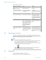
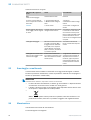
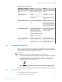
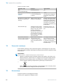
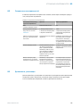
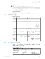
8 Troubleshooting
The Troubleshooting table indicates measures to be taken if the sensor stops working.
Table 9: Troubleshooting
LED indicator/fault pattern Cause Measures
WEO:
Green LED flashes
IO-Link communication None
Switching outputs do not
behave in accordance with
table 6
1. IO-Link communication
2. Change of the configuration
3. Short-circuit
1. None
2. Adjustment of the configura‐
tion
3. Check electrical connections
7 COMMISSIONING
12
8025304 / 2021-05-12 | SICK
Subject to change without notice

LED indicator/fault pattern Cause Measures
No object in beam path, no
output signal
Test input (Test) is not con‐
nected properly
Check connection of the test
input. When using female cable
connectors with LED indicators,
make sure the test input is
assigned correspondingly.
Yellow LED flashes Distance between sender
(WS) and receiver (WE) is
too large / Beam of WS is
not completely on WE or WE
is not aligned to WS / Front
screen and/or reflector is con‐
taminated.
Check sensing range / Clean‐
ing of the optical surfaces.
Yellow LED lights up, although
an object is in the path of the
beam.
The beam of light of a pho‐
toelectric through-beam sen‐
sor hits the receiver of
another (neighboring) photo‐
electric through-beam sensor
Swap the sender and receiver
arrangement at every sec‐
ond through-beam photoelec‐
tric sensor and ensure that
there is sufficient distance
between the through-beam
photoelectric sensors
9 Disassembly and disposal
The sensor must be disposed of according to the applicable country-specific regula‐
tions. Efforts should be made during the disposal process to recycle the constituent
materials (particularly precious metals).
NOTE
Disposal of batteries, electric and electronic devices
•
According to international directives, batteries, accumulators and electrical or
electronic devices must not be disposed of in general waste.
•
The owner is obliged by law to return this devices at the end of their life to the
respective public collection points.
•
WEEE: This symbol on the product, its package or in this document,
indicates that a product is subject to these regulations.
10 Maintenance
SICK sensors are maintenance-free.
We recommend doing the following regularly:
•
Clean the external lens surfaces
•
Check the screw connections and plug-in connections
No modifications may be made to devices.
Subject to change without notice. Specified product properties and technical data are
not written guarantees.
DISASSEMBLY AND DISPOSAL 9
8025304 / 2021-05-12 | SICK
Subject to change without notice
13

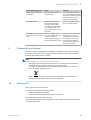
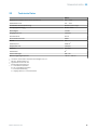
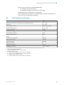
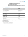
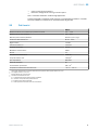
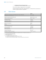
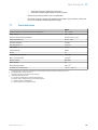
11 Technical specifications
WSE4F
Recommended sensing range for the best performance 0 m ... 7.5 m
Sensing range max. 0 m ... 10 m
Light spot diameter/distance Ø 55 mm (1,5 m) (Typ)
Supply voltage U
B
DC 10 ... 30 V
1)
Ripple ≤ 5 VSS
Output current I
max.
≤ 100 mA
Current consumption 25 mA
Communication mode COM2
IO-Link 1.1
Switching frequency 1000 Hz
2)
Max. response time ≤ 500 μs
3)
Enclosure rating IP66, IP67
Protection class III
4)
Circuit protection A, B, C, D
5)
Ambient operating temperature –40 °C ... +60 °C
1)
Limit values. U
B
connections reverse-polarity protected. Residual ripple max 5 V
PP
2)
With light / dark ratio 1:1
3)
Signal transit time with resistive load
4)
Reference voltage DC 50 V
5)
A = U
B
-connections reverse polarity protected
B = inputs and output reverse-polarity protected
C = Interference suppression
D = outputs overcurrent and short-circuit protected
11 TECHNICAL SPECIFICATIONS
14
8025304 / 2021-05-12 | SICK
Subject to change without notice

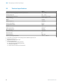
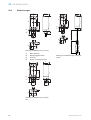
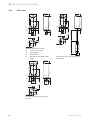
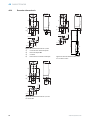
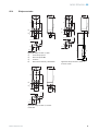
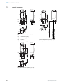
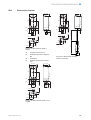
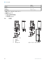
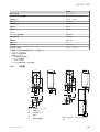
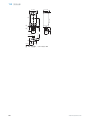
11.1 Dimensional drawings
1
4
2
3
16 (0.63) 12.1 (0.48)
9 (0.35)
5.6 (0.22)
8 (0.32)
8.1 (0.32)
3.5 (0.14) 16.6 (0.65)
37.2 (1.46)
4.7 (0.18)
3.5 (0.14)
Figure 8: Dimensional drawing 1, cable
1
Center of optical axis
2
M3 threaded mounting hole
3
Connection
4
Operating and status indicators
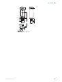
1
4
2
3
16 (0.63) 12.1 (0.48)
9 (0.35)
5.6 (0.22)
8 (0.32)
8.1 (0.32)
3.5 (0.14) 16.6 (0.65)
37.2 (1.46)
4.7 (0.18)
3.5 (0.14)
5
77 (3.03)
33 (1.3)
M8
Figure 9: Dimensional drawing 2, cable
with male connector
1
4
2
3
16 (0.63) 12.1 (0.48)
9 (0.35)
M8
(0.31)
5.6 (0.22)
8 (0.32)
11 (0.43)
3.5 (0.14) 16.6 (0.65)
40.1 (1.58)
7.6 (0.3)
3.5 (0.14)
Figure 10: Dimensional drawing 3, Male
connector, M8
TECHNICAL SPECIFICATIONS 11
8025304 / 2021-05-12 | SICK
Subject to change without notice
15


Beschriebenes Produkt
W4F
WSE4F
Hersteller
SICK AG
Erwin-Sick-Str. 1
79183 Waldkirch
Deutschland
Rechtliche Hinweise
Dieses Werk ist urheberrechtlich geschützt. Die dadurch begründeten Rechte bleiben
bei der Firma SICK AG. Die Vervielfältigung des Werks oder von Teilen dieses Werks
ist nur in den Grenzen der gesetzlichen Bestimmungen des Urheberrechtsgesetzes
zulässig. Jede Änderung, Kürzung oder Übersetzung des Werks ohne ausdrückliche
schriftliche Zustimmung der Firma SICK AG ist untersagt.
Die in diesem Dokument genannten Marken sind Eigentum ihrer jeweiligen Inhaber.
© SICK AG. Alle Rechte vorbehalten.
Originaldokument
Dieses Dokument ist ein Originaldokument der SICK AG.
2006/42/EC
NO
SAFETY
8025304 / 2021-05-12 | SICK
Subject to change without notice
17

Inhalt
12 Allgemeine Sicherheitshinweise..................................................... 19
13 Hinweise zur UL Zulassung.............................................................. 19
14 Produktbeschreibung....................................................................... 19
14.1 Bestimmungsgemäße Verwendung......................................................... 19
14.2 Bedien- und Anzeigeelemente................................................................. 19
15 Montage.............................................................................................. 20
16 Elektrische Installation..................................................................... 21
17 Zusatzfunktionen.............................................................................. 23
18 Inbetriebnahme................................................................................. 24
18.1 Ausrichtung............................................................................................... 24
18.2 Die Einsatzbedingungen prüfen:.............................................................. 25
18.3 Einstellung................................................................................................. 26
18.4 Prozessdatenstruktur............................................................................... 27
19 Störungsbehebung............................................................................ 27
20 Demontage und Entsorgung............................................................ 28
21 Wartung.............................................................................................. 28
22 Technische Daten.............................................................................. 29
22.1 Maßzeichnungen...................................................................................... 30
INHALT
18
8025304 / 2021-05-12 | SICK
Subject to change without notice

12 Allgemeine Sicherheitshinweise
■
Lesen Sie vor der Inbetriebnahme des Geräts die Betriebsanleitung.
■
Der Anschluss, die Montage und die Konfiguration des Geräts dürfen nur
von geschultem Fachpersonal vorgenommen werden.
■
2006/42/EC
NO
SAFETY
Bei diesem Gerät handelt es sich um kein sicherheitsgerichtetes Bauteil im
Sinne der EU-Maschinenrichtlinie.
■
Installieren Sie den Sensor nicht an Orten, die direkter UV-Strahlung (Son‐
nenlicht) oder sonstigen Wettereinflüssen ausgesetzt sind, ausser dies ist in der
Betriebsanleitung ausdrücklich erlaubt.
■
Bei der Inbetriebnahme ist das Gerät ausreichend vor Feuchtigkeit und Verschmut‐
zung zu schützen.
■
Die vorliegende Betriebsanleitung enthält Informationen, die während des Lebens‐
zyklus der Lichtschranke benötigt werden.
13 Hinweise zur UL Zulassung
The device shall be supplied from an isolating transformer having a secondary overcur‐
rent protective device that complies with UL 248 to be installed in the field rated either:
a) max 5 amps for voltages 0 ~ 20 V (0 ~ 28.3 V peak), or
b) 100 / Vp for voltages of 20 ~ 30 V (28.3 ~ 42.4 V peak).
Alternatively, they can be supplied from a Class 2 power supply.
UL Environmental Rating: Enclosure type 1
14 Produktbeschreibung
14.1 Bestimmungsgemäße Verwendung
Die WSE4F ist eine opto-elektronische Einweg-Lichtschranke (im Folgenden Sensor
genannt) und wird zum optischen, berührungslosen Erfassen von Sachen, Tieren und
Personen eingesetzt. Zum Betrieb ist ein Sender (WS) und ein Empfänger (WE) erfor‐
derlich. Bei jeder anderen Verwendung und bei Veränderungen am Produkt verfällt
jeglicher Gewährleistungsanspruch gegenüber der SICK AG.
14.2 Bedien- und Anzeigeelemente
ALLGEMEINE SICHERHEITSHINWEISE 12
8025304 / 2021-05-12 | SICK
Subject to change without notice
19

WSO4Fx-xxxxxxA0 WEO4Fx-xxxxxx30A00 WEO4Fx-xxxxxx00A00
4 3
1
2
4 3
1
4 3
1
BluePilot blau: Ausrichthilfe
2
Teach-Taste: Einstellung der Empfindlichkeit
3
Anzeige-LED gelb: Status Lichtempfang
4
Anzeige-LED grün: Betriebsspannung aktiv
15 Montage
Sensoren (Sender und Empfänger) an geeignete Befestigungswinkel montieren (siehe
SICK-Zubehör-Programm). Sender und Empfänger zueinander ausrichten.
14 PRODUKTBESCHREIBUNG
20
8025304 / 2021-05-12 | SICK
Subject to change without notice
A página está carregando ...
A página está carregando ...
A página está carregando ...
A página está carregando ...
A página está carregando ...
A página está carregando ...
A página está carregando ...
A página está carregando ...
A página está carregando ...
A página está carregando ...
A página está carregando ...
A página está carregando ...
A página está carregando ...
A página está carregando ...
A página está carregando ...
A página está carregando ...
A página está carregando ...
A página está carregando ...
A página está carregando ...
A página está carregando ...
A página está carregando ...
A página está carregando ...
A página está carregando ...
A página está carregando ...
A página está carregando ...
A página está carregando ...
A página está carregando ...
A página está carregando ...
A página está carregando ...
A página está carregando ...
A página está carregando ...
A página está carregando ...
A página está carregando ...
A página está carregando ...
A página está carregando ...
A página está carregando ...
A página está carregando ...
A página está carregando ...
A página está carregando ...
A página está carregando ...
A página está carregando ...
A página está carregando ...
A página está carregando ...
A página está carregando ...
A página está carregando ...
A página está carregando ...
A página está carregando ...
A página está carregando ...
A página está carregando ...
A página está carregando ...
A página está carregando ...
A página está carregando ...
A página está carregando ...
A página está carregando ...
A página está carregando ...
A página está carregando ...
A página está carregando ...
A página está carregando ...
A página está carregando ...
A página está carregando ...
A página está carregando ...
A página está carregando ...
A página está carregando ...
A página está carregando ...
A página está carregando ...
A página está carregando ...
A página está carregando ...
A página está carregando ...
A página está carregando ...
A página está carregando ...
A página está carregando ...
A página está carregando ...
A página está carregando ...
A página está carregando ...
A página está carregando ...
A página está carregando ...
A página está carregando ...
A página está carregando ...
A página está carregando ...
A página está carregando ...
A página está carregando ...
A página está carregando ...
A página está carregando ...
A página está carregando ...
A página está carregando ...
A página está carregando ...
A página está carregando ...
A página está carregando ...
A página está carregando ...
A página está carregando ...
A página está carregando ...
A página está carregando ...
A página está carregando ...
A página está carregando ...
A página está carregando ...
A página está carregando ...
A página está carregando ...
A página está carregando ...
A página está carregando ...
A página está carregando ...
A página está carregando ...
A página está carregando ...
A página está carregando ...
A página está carregando ...
A página está carregando ...
A página está carregando ...
A página está carregando ...
A página está carregando ...
A página está carregando ...
A página está carregando ...
A página está carregando ...
A página está carregando ...
A página está carregando ...
A página está carregando ...
A página está carregando ...
A página está carregando ...
A página está carregando ...
A página está carregando ...
A página está carregando ...
A página está carregando ...
A página está carregando ...
A página está carregando ...
A página está carregando ...
A página está carregando ...
A página está carregando ...
A página está carregando ...
A página está carregando ...
-
 1
1
-
 2
2
-
 3
3
-
 4
4
-
 5
5
-
 6
6
-
 7
7
-
 8
8
-
 9
9
-
 10
10
-
 11
11
-
 12
12
-
 13
13
-
 14
14
-
 15
15
-
 16
16
-
 17
17
-
 18
18
-
 19
19
-
 20
20
-
 21
21
-
 22
22
-
 23
23
-
 24
24
-
 25
25
-
 26
26
-
 27
27
-
 28
28
-
 29
29
-
 30
30
-
 31
31
-
 32
32
-
 33
33
-
 34
34
-
 35
35
-
 36
36
-
 37
37
-
 38
38
-
 39
39
-
 40
40
-
 41
41
-
 42
42
-
 43
43
-
 44
44
-
 45
45
-
 46
46
-
 47
47
-
 48
48
-
 49
49
-
 50
50
-
 51
51
-
 52
52
-
 53
53
-
 54
54
-
 55
55
-
 56
56
-
 57
57
-
 58
58
-
 59
59
-
 60
60
-
 61
61
-
 62
62
-
 63
63
-
 64
64
-
 65
65
-
 66
66
-
 67
67
-
 68
68
-
 69
69
-
 70
70
-
 71
71
-
 72
72
-
 73
73
-
 74
74
-
 75
75
-
 76
76
-
 77
77
-
 78
78
-
 79
79
-
 80
80
-
 81
81
-
 82
82
-
 83
83
-
 84
84
-
 85
85
-
 86
86
-
 87
87
-
 88
88
-
 89
89
-
 90
90
-
 91
91
-
 92
92
-
 93
93
-
 94
94
-
 95
95
-
 96
96
-
 97
97
-
 98
98
-
 99
99
-
 100
100
-
 101
101
-
 102
102
-
 103
103
-
 104
104
-
 105
105
-
 106
106
-
 107
107
-
 108
108
-
 109
109
-
 110
110
-
 111
111
-
 112
112
-
 113
113
-
 114
114
-
 115
115
-
 116
116
-
 117
117
-
 118
118
-
 119
119
-
 120
120
-
 121
121
-
 122
122
-
 123
123
-
 124
124
-
 125
125
-
 126
126
-
 127
127
-
 128
128
-
 129
129
-
 130
130
-
 131
131
-
 132
132
-
 133
133
-
 134
134
-
 135
135
-
 136
136
-
 137
137
-
 138
138
-
 139
139
-
 140
140
-
 141
141
-
 142
142
-
 143
143
-
 144
144
-
 145
145
-
 146
146
-
 147
147


em outros idiomas
- español: SICK WSE4F Instrucciones de operación
- français: SICK WSE4F Mode d'emploi
- italiano: SICK WSE4F Istruzioni per l'uso
- English: SICK WSE4F Operating instructions
- русский: SICK WSE4F Инструкция по эксплуатации
- Deutsch: SICK WSE4F Bedienungsanleitung
- polski: SICK WSE4F Instrukcja obsługi
- 日本語: SICK WSE4F 取扱説明書
Artigos relacionados
-
SICK WSE26 Instruções de operação
-
-
-
-
-
-
-
-
-