OTTO 5R6=1 Socket Adapter Manual do usuário
- Tipo
- Manual do usuário

5R6=1
5R6=2
5R6=3
5Y14=1
5Y14=2
5Y14=3
Gebrauchsanweisung �������������������������������������������������������������������� 4
Instructions for use ������������������������������������������������������������������������ 9
Instructions d‘utilisation ���������������������������������������������������������������� 14
Istruzioni per l’uso ����������������������������������������������������������������������� 19
Instrucciones de uso �������������������������������������������������������������������� 24
Manual de utilização ��������������������������������������������������������������������� 29
Gebruiksaanwijzing ���������������������������������������������������������������������� 33
Bruksanvisning ���������������������������������������������������������������������������� 39
Οδηγίες χρήσης �������������������������������������������������������������������������� 44
5R6=*, 5Y14=*

2 | Ottobock
4
2
3
1

Ottobock | 3
6 7
5

4 | Ottobock
Deutsch
Datum der letzten Aktualisierung: 2021-06-21
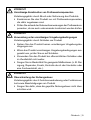
• Lesen Sie dieses Dokument vor Gebrauch des Produkts aufmerksam
durch und beachten Sie die Sicherheitshinweise.
•
Weisen Sie den Benutzer in den sicheren Gebrauch des Produkts ein.
•
Wenden Sie sich an den Hersteller, wenn Sie Fragen zum Produkt
haben oder Probleme auftreten.
•
Melden Sie jedes schwerwiegende Vorkommnis im Zusammenhang mit
dem Produkt, insbesondere eine Verschlechterung des Gesundheits-
zustands, dem Hersteller und der zuständigen Behörde Ihres Landes.
• Bewahren Sie dieses Dokument auf.
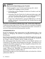
1 Verwendungszweck und Beschreibung
Die Adapterschale 5R6 ist ausschließlich für die prothetische Versorgung
der unteren Extremität einzusetzen.
Zugelassen bis max. 100 kg Körpergewicht.
Die Adapterschale ist für Unterschenkel- und Oberschenkelprothesen ge-
eignet und wird zur lösbaren Verbindung von selbsttragenden Kunststoff-
schäften mit dem Modular-System eingesetzt.
2 Sicherheit
2.1 Bedeutung der Warnsymbolik
VORSICHT
Warnung vor möglichen Unfall- und Verletzungsgefahren.
2.2 Allgemeine Sicherheitshinweise
VORSICHT
Überbeanspruchung des Produkts
Verletzungsgefahr durch Bruch tragender Teile
•
Setzen Sie das Produkt entsprechend des angegebenen Ein-
satzgebiets ein (Einsatzgebiet).

Ottobock | 5
VORSICHT
Unzulässige Kombination von Prothesenkomponenten
Verletzungsgefahr durch Bruch oder Verformung des Produkts
•
Kombinieren Sie das Produkt nur mit Prothesenkomponenten,
die dafür zugelassen sind.
•
Prüfen Sie anhand der Gebrauchsanweisungen der Prothesenkom-
ponenten, ob sie auch untereinander kombiniert werden dürfen.
VORSICHT
Verwendung unter unzulässigen Umgebungsbedingungen
Verletzungsgefahr durch Schäden am Produkt
•
Setzen Sie das Produkt keinen unzulässigen Umgebungsbe-
dingungen aus.
• Wenn das Produkt unzulässigen Umgebungsbedingungen aus-
gesetzt war, prüfen Sie es auf Schäden.
• Verwenden Sie das Produkt bei offensichtlichen Schäden oder
im Zweifelsfall nicht weiter.
• Sorgen Sie im Bedarfsfall für geeignete Maßnahmen (z. B. Rei-
nigung, Reparatur, Ersatz, Kontrolle durch den Hersteller oder
eine Fachwerkstatt, etc.).
VORSICHT
Überschreitung der Nutzungsdauer
Verletzungsgefahr durch Funktionsveränderung oder Funktionsver-
lust sowie Beschädigungen am Produkt
• Sorgen Sie dafür, dass die geprüfte Nutzungsdauer nicht über-
schritten wird.

6 | Ottobock
VORSICHT
Mechanische Beschädigung des Produkts
Verletzungsgefahr durch Funktionsveränderung oder -verlust
• Arbeiten Sie sorgfältig mit dem Produkt.
•
Prüfen Sie ein beschädigtes Produkt auf Funktion und Ge-
brauchsfähigkeit.
•
Verwenden Sie das Produkt bei Funktionsveränderungen oder
-verlust nicht weiter (siehe „Anzeichen von Funktionsveränderun-
gen oder -verlust beim Gebrauch“ in diesem Kapitel).
• Sorgen Sie im Bedarfsfall für geeignete Maßnahmen (z. B. Re-
paratur, Austausch, Kontrolle durch den Kunden-Service des
Herstellers, etc.).
Anzeichen von Funktionsveränderungen oder -verlust beim Gebrauch
Funktionsveränderungen können sich z. B. durch ein verändertes Gangbild,
eine veränderte Positionierung der Prothesenkomponenten zueinander so-
wie durch Geräuschentwicklung bemerkbar machen.
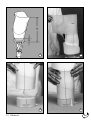
3 Arbeitshilfe 5Y14
Die 5Y14 Arbeitshilfe steht entsprechend der 5R6 Adapterschale in drei
Größen zur Verfügung. Sie erleichtert die paßgerechte Formgebung der
Modellkuppe.
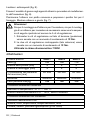
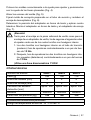
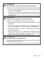
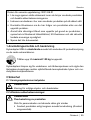
Das Orientierungsmaß für die Position der Arbeitshilfe ergibt sich aus der
Distanz Tuber bis Adapterschale-Unterkante (a) minus Tiefe der Arbeitshilfe
(b): Größe 1 = 50 mm, Größe 2 = 45 mm, Größe 3 = 35 mm.
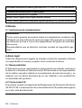
Zum stellungsgerechten Einordnen Lotlinien auf das Modell zeichnen und
Trolenfolien für die distale Gipsverlängerung anbringen. Trolenfolie bis zum
angezeichneten Maß waagerecht mit Gips ausgießen (entspricht der obe-
ren Kante der Arbeitshilfe) (Abb. 2).
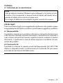
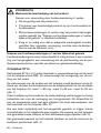
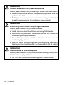
Zur besseren Verbindung einige Drahtstifte in den erhärteten Gipsansatz
nageln. Öffnung der Arbeitshilfe mit Gipsisoliercreme isolieren und mit
dünnüssigem Gipsbrei ausfüllen (Abb. 3).
Gipsmodell passgenau auf die Arbeitshilfe setzen und anhand der Lotlinien
positionieren (Abb. 4).

Ottobock | 7
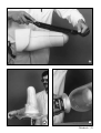
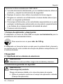
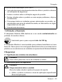
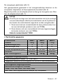
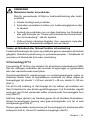
Übergänge des Modells glätten (Abb. 5).
Präpariertes Gipsmodell in das Formwerkzeug einspannen und Stumpf-
bettung aus thermoplastischer Kunststoffplatte tiefziehen (Abb. 6).
Position der Adapterschale bestimmen und vier Bohrungen anbringen. Ad-
apterschale und Schaftadapter montieren (Abb. 7).
Achtung!
Sowohl zur Montage an den Schaftansatz und zur Montage eines
Schaftadapters, muss beim Anziehen der je 4 Senkschrauben fol-
gende Reihenfolge eingehalten werden:
1. Die beiden Senkschrauben auf der Zugseite (posterior) sind
drehmomentgesteuert auf 12 Nm festzuziehen.
2. Die zwei gegenüberliegenden Senkschrauben (anterior) sind
danach drehmomentgesteuert mit 12 Nm festzuziehen.
Drehmomentschlüssel 710D4 benutzen!
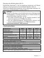
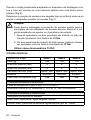
4 Technische Daten
Artikelnummer 5R6=1 5R6=2 5R6=3
Gewicht [g] 160 135 115
Systemhöhe [mm] 4 4 4
Einbauhöhe [mm] 4 4 4
Umfang Stumpfende [mm] ca. 400 ca. 320 ca. 250
Material Aluminium Aluminium Aluminium
Max. Patientengewicht [kg] 100 100 100
Zulässige Umgebungsbedingungen
Einsatztemperaturbereich -10 °C bis +60°C
Zulässige relative Luftfeuchtigkeit 0 % bis 90 %, nicht kondensierend
Unzulässige Umgebungsbedingungen
Mechanische Vibrationen oder Stöße
Schweiß, Urin, Süßwasser, Salzwasser, Säuren
Staub, Sand, stark hygroskopische Partikel (z. B. Talkum)

8 | Ottobock
5 Handhabung
5.1 Wartungshinweise
Hinweis:
Grundsätzlich werden alle modularen Adapter von Ottobock mit drei Mil-
lionen Belastungszyklen geprüft. Dies entspricht, je nach Aktivitätsgrad
des Amputierten, einer Nutzungsdauer von drei bis fünf Jahren.
Wir empfehlen grundsätzlich regelmäßig jährliche Sicherheitskontrollen
durchzuführen.
6 Rechtliche Hinweise
Alle rechtlichen Bedingungen unterliegen dem jeweiligen Landesrecht des
Verwenderlandes und können dementsprechend variieren.
6.1 Haftung
Der Hersteller haftet, wenn das Produkt gemäß den Beschreibungen und
Anweisungen in diesem Dokument verwendet wird. Für Schäden, die durch
Nichtbeachtung dieses Dokuments, insbesondere durch unsachgemäße
Verwendung oder unerlaubte Veränderung des Produkts verursacht wer-
den, haftet der Hersteller nicht.
6.2 CE-Konformität
Das Produkt erfüllt die Anforderungen der Verordnung (EU) 2017/745 über
Medizinprodukte. Die CE-Konformitätserklärung kann auf der Website des
Herstellers heruntergeladen werden.

Ottobock | 9
English
Date of last update: 2021-06-21
•
Please read this document carefully before using the product and
observe the safety notices.
• Instruct the user in the safe use of the product.
• Please contact the manufacturer if you have questions about the pro-
duct or in case of problems.
•
Report each serious incident in connection with the product, in particu-
lar a worsening of the state of health, to the manufacturer and to the
relevant authority in your country.
• Please keep this document for your records.
1 Application and description
The 5R6 Modular Adapter is to be used exclusively for lower limb pros-
thetic ttings.
Approved for a body weight of up to 100 kg.
The Modular Adapter is suitable for transtibial [below-knee] and transfemo-
ral (above-knee) prostheses. It is used to create a detachable connection
between thermoplastic sockets or frames and the Modular System com-
ponents.
2 Safety
2.1 Explanation of warning symbols
CAUTION
Warning regarding possible risks of accident or injury.

10 | Ottobock
2.2 General safety instructions
CAUTION
Excessive strain on the product
Risk of injury due to breakage of load-bearing components
•
Use the product according to the specied area of application
(Area of application).
CAUTION
Unallowable combination of prosthetic components
Risk of injury due to breakage or deformation of the product
• Only combine the product with prosthetic components that are
approved for that purpose.
• Based on the instructions for use of the prosthetic components,
verify that they may be combined with each other.
CAUTION
Use under unallowable environmental conditions
Risk of injury due to damage to the product
•
Do not expose the product to unallowable environmental conditions.
•
If the product has been exposed to unallowable environmental
conditions, check it for damage.
•
If damage is apparent or in case of doubt, do not continue using
the product.
•
Take suitable measures if required (e.g. cleaning, repair, replace-
ment, inspection by the manufacturer or a specialist workshop etc.).
CAUTION
Exceeding the service life
Risk of injury due to change in or loss of functionality and damage
to the product
• Ensure that the approved service life is not exceeded.

Ottobock | 11
CAUTION
Mechanical damage to the product
Risk of injury due to change in or loss of functionality
• Use caution when working with the product.
•
If the product is damaged, check it for proper function and
readiness for use.
•
In case of changes in or loss of functionality, do not continue
using the product (see "Signs of changes in or loss of functionality
during use" in this section).
•
Take any necessary measures (e.g. repair, replacement, inspec-
tion by the manufacturer's customer service, etc.).
Signs of changes in or loss of functionality during use
Among other factors, changes in functionality can be indicated by an alte-
red gait pattern, a change in the positioning of the prosthetic components
relative to each other and by the development of noises.
3 5Y14 Tool
The 5Y14 Tool is available in three sizes to correspond with the 5R6 Modu-
lar Adapters. This tool makes it easier to accurately shape the distal end of
the plaster extension of a plaster positive or vacuum formed inner socket.
To calculate the amount of space needed for fabrication, measure the dis-
tance from the ischial tuberosity to the lower edge of the modular adapter
(a) and substract the tool depth (b): Size 1 = 50 mm, Size 2 = 45 mm, Size 3
= 35 mm (g. 1).
Draw reference lines on the positive to show the desired alignment. Use a
piece of polyethylene sheet material to extend the model (inner socket). Pour
plaster into the polyethylene sheet, lling to the marked height (correspond-
ing to the upper edge of the tool). Square off the end of the extension with
respect to the alignment lines (g. 2).
For a stronger bond, drive a few brads into the hardened plaster insert.
Coat the inner surface of the 5Y14 Tool with plaster parting agent cream.
Then, ll in with thin plaster (g. 3).
Set the plaster model precisely on the tool and align using the plumb lines
drawn on earlier (g. 4).

12 | Ottobock
Smooth the transition area on the model (g. 5).
Clamp the prepared model (inner socket) into the vacuum forming tools.
Pull the socket or outer support frame using a thermoplastic sheet (g. 6).
Determine the position of the socket, then drill four holes to mount the modu-
lar adapter to the socket (g. 7).
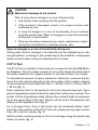
Attention!
Both when mounting to the socket attachment block and when
mounting a socket adapter, tighten the four screws in the follow-
ing order:
1. Tighten both countersunk head screws on the displacement
(posterior) side with controlled torque to 12 Nm.
2. Afterwards, tighten the two countersunk head screws on the
opposite side with controlled torque 12 Nm.
Use a 710D4 Torque Wrench!
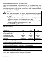
4 Technical data
Article number 5R6=1 5R6=2 5R6=3
Weight [g] 160 135 115
System height [mm] 4 4 4
Build height [mm] 4 4 4
Residual limb end
circumference [mm]
Approx.
400
Approx.
320
Approx.
250
Material Aluminium Aluminium Aluminium
Max. patient weight [kg] 100 100 100
Allowable environmental conditions
Temperature range for use: -10 °C to +60°C
Allowable relative humidity 0 % to 90 %, non-condensing
Unallowable environmental conditions
Mechanical vibrations or impacts
Perspiration, urine, fresh water, salt water, acids
Dust, sand, highly hygroscopic particles (e.g. talcum)

Ottobock | 13
5 Handling
5.1 Maintenance instructions
Note:
As a basic principle, all Ottobock modular adapters are subjected to
tests involving three million load cycles. Depending on the amputee's
activity this corresponds to a service life of three to ve years.
We recommend carrying out regular safety checks once a year.
6 Legal information
All legal conditions are subject to the respective national laws of the country
of use and may vary accordingly.
6.1 Liability
The manufacturer will only assume liability if the product is used in accor-
dance with the descriptions and instructions provided in this document. The
manufacturer will not assume liability for damage caused by disregard of
this document, particularly due to improper use or unauthorised modica-
tion of the product.
6.2 CE conformity
The product meets the requirements of Regulation (EU) 2017/745 on medi-
cal devices. The CE declaration of conformity can be downloaded from the
manufacturer's website.

14 | Ottobock
Français
Date de la dernière mise à jour : 2021-06-21
•
Veuillez lire attentivement l’intégralité de ce document avant d’utiliser
le produit ainsi que respecter les consignes de sécurité.
• Apprenez à l’utilisateur comment utiliser son produit en toute sécurité.
• Adressez-vous au fabricant si vous avez des questions concernant le
produit ou en cas de problèmes.
•
Signalez tout incident grave survenu en rapport avec le produit, no-
tamment une aggravation de l’état de santé, au fabricant et à l’autorité
compétente de votre pays.
• Conservez ce document.
1 Champs d'application et description
L'admission d'emboîtage 5R6 est destiné exclusivement à l'appa reillage
prothétique des membres inférieurs.
Admis pour les patients dont le poids n’excède pas 100 kg.
La coque d'adaptateur est conçue pour les prothèses de jambe et de
cuisse, elle est utilisée comme liaison démontable entre les manchons en
matière plastique auto-porteurs et le système modulaire.
2 Sécurité
2.1 Signication des symboles de mise en garde
PRUDENCE
Mise en garde contre les éventuels risques d’accidents et de bles-
sures.

Ottobock | 15
2.2 Consignes générales de sécurité
PRUDENCE
Sollicitation excessive du produit
Risque de blessure occasionnée par la rupture de pièces porteuses
•
Utilisez le produit conformément au domaine d’application indiqué
(Domaine d’application).
PRUDENCE
Combinaison non autorisée des composants prothétiques
Risque de blessure occasionnée par une rupture ou une déforma-
tion du produit
• Combinez le produit uniquement avec des composants prothé-
tiques autorisés à cet effet.
• Vériez à l’aide des instructions d’utilisation des différents com-
posants prothétiques que leur combinaison est bien autorisée.
PRUDENCE
Utilisation dans des conditions d’environnement non autori-
sées
Risque de blessure provoquée par un produit endommagé
• N’exposez pas le produit à des conditions d’environnement non
autorisées.
•
En cas d’exposition à des conditions d’environnement non auto-
risées, vériez que le produit n’a subi aucun dommage.
•
Cessez d’utiliser le produit en cas de dommages évidents ou
en cas de doute.
•
Si besoin, prenez les mesures nécessaires (par ex. nettoyage,
réparation, remplacement, contrôle par le fabricant ou un atelier
spécialisé, etc.).

16 | Ottobock
PRUDENCE
Dépassement de la durée d’utilisation
Risque de blessure provoqué par une modication de fonctionna-
lité ou une perte de fonctionnalité et des dégradations du produit
•
Veillez à ce que la durée d’utilisation dénie ne soit pas dépassée.
PRUDENCE
Dégradation mécanique du produit
Risque de blessure due à une modication ou une perte de fonc-
tionnalité
• Manipulez le produit avec précaution.
•
Tout produit endommagé doit être vérié an de juger s’il est
encore fonctionnel.
•
En cas de modication ou perte de fonctionnalité, cessez d’utiliser
le produit (voir dans le présent chapitre le point « Signes de modi-
cation ou de perte de fonctionnalité détectés lors de l’utilisation »).
• Si besoin, prenez les mesures nécessaires (par ex. réparation,
remplacement, contrôle par le service après-vente du fabricant, etc.).
Signs of changes in or loss of functionality during use
Among other factors, changes in functionality can be indicated by an alte-
red gait pattern, a change in the positioning of the prosthetic components
relative to each other and by the development of noises.
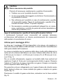
3 Outillage d'aide 5Y14
Le gabarit 5Y14 existe, comme admission d'emboitage 5R6, en trois tailles.
Il permet de faciliter le formage correct de la calotte du positif.
La cote d'orientation pour la position de l'outillage résulte de la distance
entre le Tuber et l'arête inférieure de la coque d'adaptateur (a), moins la
profondeur de l'outillage (b): taille 1 = 50 mm, taille 2 = 45 mm, taille 3 =
35 mm (illustration 1).
Dessiner des lignes verticales sur le modèle pour obtenir un positionnement
correct et apposer des feuilles pour la rallonge distale en plâtre. Mouler la
feuille avec le plâtre horizontalement jusqu'à la cote qui a été tracée (cor-
respond à l'arête supérieure de l'outillage d'aide) (illustration 2).

Ottobock | 17
Pour assurer une meilleure liaison, planter quelques pointes dans le plâtre
durci. Isoler l'ouverture de l'outillage avec de la crème d'isolation pour
plâtre et la remplir avec du plâtre bien uide (illustration 3).
Poser le modèle en plâtre sur l'outillage d'aide en l'ajustant bien et le posi-
tionner à l'aide des lignes verticales (illustration 4).
Lisser les transitions sur le positif (illustration 5).
Serrer dans le moule le modèle en plâtre qui a été confectionné et emboutir
la plaque thermoplastique qui constituera l'emboîture (illustration 6).
Déterminer la position de la coque d'adaptateur et percer quatre trous.
Monter la coque et l'adaptateur de manchon (illustration 7).
Attention !
Pour le montage sur l'admission d'emboîture ainsi que pour le mon-
tage d’un adaptateur d’emboîture, il faut procéder dans l’ordre sui-
vant lors du serrage des 4 vis à tête fraisée :
1. Il faut serrer les deux vis à tête fraisée du côté de la traction
(derrière) au couple de 12 Nm.
2. Les deux vis à tête fraisée situées l'une à côté de l'autre (devant)
doivent ensuite être serrées au couple de 12 Nm.
Utiliser une clé dynamométrique 701D1 !
4 Caractéristiques techniques
Référence de l’article 5R6=1 5R6=2 5R6=3
Poids [g] 160 135 115
Hauteur du système [mm] 4 4 4
Hauteur de montage [mm] 4 4 4
Circonférence de l’extrémité
du moignon [mm]
env. 400 env. 320 env. 250
Matériau Aluminium Aluminium Aluminium
Poids max. du patient [kg] 100 100 100
Conditions d’environnement autorisées
Plage de température de fonctionnement -10°C à +60°C
Humidité relative de l’air admise 0 % à 90 %, sans condensation

18 | Ottobock
Conditions d’environnement non autorisées
Vibrations mécaniques ou chocs
Sueur, urine, eau douce, eau salée, acides
Poussières, grains de sable, particules hygroscopiques (talc par ex.)
5 Mise en place
5.1 Consignes d’entretien
Remarque:
En général, l’ensemble des adaptateurs modulaires Ottobock sont
contrôlés au moyen de trois millions de cycles de charge. Cela corres-
pond à une durée d’utilisation comprise entre trois et cinq ans selon le
niveau d’activité de la personne amputée.
Nous recommandons en principe de procéder régulièrement à des
contrôles de sécurité annuels.
6 Informations légales
Toutes les conditions légales sont soumises à la législation nationale du
pays d’utilisation concerné et peuvent donc présenter des variations en
conséquence.
6.1 Responsabilité
Le fabricant est responsable si le produit est utilisé conformément aux de-
scriptions et instructions de ce document. Le fabricant décline toute respon-
sabilité pour les dommages découlant d’un non-respect de ce document,
notamment d’une utilisation non conforme ou d’une modication non auto-
risée du produit.
6.2 Conformité CE
Ce produit répond aux exigences du Règlement (UE) 2017/745 relatif aux
dispositifs médicaux. La déclaration de conformité CE peut être téléchar-
gée sur le site Internet du fabricant.

Ottobock | 19
Italiano
Data dell'ultimo aggiornamento: 2021-06-21
• Leggere attentamente il presente documento prima di utilizzare il pro-
dotto e osservare le indicazioni per la sicurezza.
• Istruire l'utente sull'utilizzo sicuro del prodotto.
•
Rivolgersi al fabbricante in caso di domande sul prodotto o all'insorgere
di problemi.
• Segnalare al fabbricante e alle autorità competenti del proprio paese
qualsiasi incidente grave in connessione con il prodotto, in particolare
ogni tipo di deterioramento delle condizioni di salute.
• Conservare il presente documento.
1 Campo d’impiego e descrizione
L’attacco 5R6 è indicato esclusivamente per la costruzione di protesi di
arto inferiore.
Omologato per un peso corporeo no a max. 100 kg.
L’attacco è indicato per protesi transtibiali e transfemorali per collegare
l’invasatura in materiale termoplastico al sistema modulare.
2 Sicurezza
2.1 Signicato dei simboli utilizzati
CAUTELA
Avvertenza relativa a possibili pericoli di incidente e lesioni.
2.2 Indicazioni generali per la sicurezza
CAUTELA
Sollecitazione eccessiva del prodotto
Pericolo di lesione per rottura di componenti portanti
•
Utilizzare il prodotto rispettando il campo di impiego indicato
(Campo d'impiego).

20 | Ottobock
CAUTELA
Combinazione non consentita di componenti della protesi
Pericolo di lesione per rottura o deformazione del prodotto
•
Combinare il prodotto solo con i componenti protesici apposit-
amente omologati.
•
Controllare anche, in base alle istruzioni per l’uso dei componenti
protesici, se possono essere combinati tra di loro.
CAUTELA
Utilizzo in condizioni ambientali non consentite
Pericolo di lesione per danni al prodotto
• Non esporre il prodotto a condizioni ambientali non consentite.
•
Se il prodotto è stato sottoposto a condizioni ambientali non
consentite, controllare se è danneggiato.
•
Non continuare a utilizzare il prodotto in presenza di danni evi-
denti o in caso di dubbio.
• Se necessario, prendere provvedimenti adeguati (p. es. pulizia,
riparazione, sostituzione, controllo da parte del produttore o di
un'ofcina specializzata, ecc.).
CAUTELA
Superamento della durata di utilizzo
Pericolo di lesione dovuto a cambiamento o perdita di funzionalità
e danni al prodotto
•
Assicurarsi di non superare la durata di utilizzo certicata del
prodotto.
A página está carregando...
A página está carregando...
A página está carregando...
A página está carregando...
A página está carregando...
A página está carregando...
A página está carregando...
A página está carregando...
A página está carregando...
A página está carregando...
A página está carregando...
A página está carregando...
A página está carregando...
A página está carregando...
A página está carregando...
A página está carregando...
A página está carregando...
A página está carregando...
A página está carregando...
A página está carregando...
A página está carregando...
A página está carregando...
A página está carregando...
A página está carregando...
A página está carregando...
A página está carregando...
A página está carregando...
A página está carregando...
A página está carregando...
A página está carregando...
-
 1
1
-
 2
2
-
 3
3
-
 4
4
-
 5
5
-
 6
6
-
 7
7
-
 8
8
-
 9
9
-
 10
10
-
 11
11
-
 12
12
-
 13
13
-
 14
14
-
 15
15
-
 16
16
-
 17
17
-
 18
18
-
 19
19
-
 20
20
-
 21
21
-
 22
22
-
 23
23
-
 24
24
-
 25
25
-
 26
26
-
 27
27
-
 28
28
-
 29
29
-
 30
30
-
 31
31
-
 32
32
-
 33
33
-
 34
34
-
 35
35
-
 36
36
-
 37
37
-
 38
38
-
 39
39
-
 40
40
-
 41
41
-
 42
42
-
 43
43
-
 44
44
-
 45
45
-
 46
46
-
 47
47
-
 48
48
-
 49
49
-
 50
50


OTTO 5R6=1 Socket Adapter Manual do usuário
- Tipo
- Manual do usuário
em outras línguas
- español: OTTO 5R6=1 Socket Adapter Manual de usuario
- français: OTTO 5R6=1 Socket Adapter Manuel utilisateur
- italiano: OTTO 5R6=1 Socket Adapter Manuale utente
- Nederlands: OTTO 5R6=1 Socket Adapter Handleiding
Outros documentos
-
Ottobock 4R1 Manual do usuário
-
Ottobock 7E5 Manual do usuário
-
Ottobock 5R2 Manual do usuário
-
Ottobock 3R80 Manual do usuário
-
Ottobock 4R160=1 Delrin KISS Kit Shuttle Lock Lanyard Systems Manual do usuário
-
Ottobock 8K5=* Physo Passive Hands Instruções de operação
-
Otto Bock Kenevo 4X840 Instructions For Use Manual
-
-
-