
2
3
3
4

· 2 ·
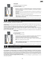
This tool has been specially developed to help with the extraction of the copper sealing washers used to seal
diesel injectors in place where they enter the cylinder head.
The washers are located in the head which is at the bottom of the injector.
Often the washer is so deep into the cylinder which makes extraction using a pick near impossible.
The injector seals are prone to failure, and with the addition of carbon build up around them, the extraction
becomes even more dicult.
The tool has been tapered and threaded so that it screws into the centre of the washer, providing more grip. Now,
the slide hammer can be used to break the seal between the washer and the cylinder head, which will allow its
extraction.
It is not advised that technicians use unsuitable tools or equipment, as they run the risk of damaging the injectors
and themselves because of the solenoids.
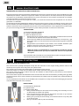
A = Diesel Injector Seal Puller
B = Cylinder Head
C= Copper Sealing Ring
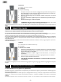
1. Firstly, remove the injector and clean the surrounding area carefully so as not
to allow debris to fall into the cylinder.
2. Enter the tapered end of the tool into the injector and twist, as you would a
screw, until the tool grips the copper washer.
3. Making sure you keep the shaft steady, use the slide hammer to tap the puller
up to free the seal.
4. Now you should be able to pull the seal freely.
Esta herramienta ha sido especialmente diseñada para favorecer la extracción de las juntas de sellado de cobre
utilizadas para sellar la culata de los inyectores diesel. Las juntas están en la culata, situada en la parte inferior
del inyector de combustible. Ocasionalmente, la junta se encuentra en una posición tan profunda en el cilindro
que hace imposible su extracción usando un pico.
Los sellos de los inyectores son propensos a fallar, y su extracción resulta aún más complicada con el carbono
generado a su alrededor.
La herramienta ha sido debidamente alada para proporcionar agarre y poder atornillarse al centro de la junta.
De esta manera, el martillo deslizante puede ser usado para romper la junta entre la arandela y el cilindro, permi-
tiendo su extracción. No se recomienda a los técnicos el uso de herramientas u otro equipamiento no adecuados,
ya que corren el riesgo de dañar los inyectores y sufrir daños personales a causa de los solenoides.
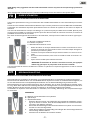
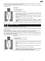
A = Extractor De Anillos De Sellado
B = Culata o Cabeza del Motor
C = Anillo de Sellado de Cobre
1. Extraiga el inyector y limpie el área a su alrededor cuidadosamente evitando
que los restos de residuos entren dentro del cilindro.
2. Inserte la parte alada de la herramienta de extracción en el inyector y gire
igual que lo haría con una rosca hasta que la herramienta agarre la arandela
de cobre.
3. Asegurándose que mantiene el eje estable, use el martillo deslizante para
deslizar el extractor hacia arriba y liberar la junta de sellado.
4. Debería ser capaz ahora de extraer la junta.
Se recomienda usar el martillo en cortos deslizamientos para conseguir una extrac-
ción efectiva de la junta de la cabeza del cilindro.

· 3 ·
Dieses Werkzeug ist speziell für die Extraktion von Kupferdichtscheiben von Dieselmotor-Injektoren konzipiert.
Das Entfernen der Dichtscheiben von verschleißbehafteten Injektoren bereitet oft erhebliche Schwierigkeiten, da
sie sich üblicherweise tief in den Zylinderköpfen benden und mit Kohlenstoablagerungen bedeckt sind.
Dieses Werkzeug hat eine konische Einengung und ein Gewinde, das für einen zuverlässigeren Gri der Schei-
be sorgt. Nach dem Gri kann die Dichtung zwischen der Unterlegscheibe und dem Zylinderkopf mit Hilfe eines
Schlag-Abziehers zerstört werden, wodurch es möglich ist, die Unterlegscheibe herauszuziehen.
Um Schäden an Injektoren oder Solenoiden zu vermeiden, ist es wichtig, Werkzeuge des entsprechenden Typs
zu verwenden.
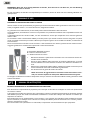
A = Abzieher von Dichtscheiben von Injektoren
B = Zylinderkopf
C = Kupferdichtscheibe
1. Entfernen Sie den Injektor und reinigen Sie die umgebende Oberäche vorsich-
tig. Es ist darauf zu achten, dass die Verschleißprodukte und andere Fremdkör-
per nicht in den Zylinder gelangen.
2. Setzen Sie das Werkzeug mit dem konischen Ende in en Injektor ein und schrau-
ben Sie es in die Unterlegscheibe.
3. Halten Sie das Werkzeug gleichmäßig und schlagen Sie die Unterlegscheibe mit
einem Schlag-Abzieher heraus.
4. Danach kann die Scheibe frei extrahiert werden.
Cet outil est spécialement conçu pour l’extraction des rondelles d’étanchéité en cuivre des brûleurs pour moteurs
diesel.
L’extraction des rondelles d’étanchéité des brûleurs sujets à l’usure présente souvent des dicultés considérables,
puisqu’elles sont d’habitude disposées profondément dans les culasses du cylindre et recouvertes du dépôt de
calamine.
Cet outil a le rétrécissement conique et le letage, ce qui assure la prise plus able de la rondelle. Après la prise,
le joint entre la rondelle et la culasse du cylindre peut être détruit à l’aide du arrache à secousses, en assurant la
possibilité de l’extraction de la rondelle.
Pour éviter l’endommagement des brûleurs ou des solénoïdes, il est important d’utiliser des outils du type appro-
prié.
A = Arrache-rondelles des brûleurs
B = Culasse du cylindre
C = Rondelle d’étanchéité en cuivre
1. Retirer le brûleur et nettoyer délicatement la surface environnante. Il est im-
portant de s’assurer que les produits d’usure et d’autres objets étrangers ne
pénètrent pas dans le cylindre.
2. Introduire l’outil par l’extrémité conique dans le brûleur et le visser à la ron-
delle.
3. En tenant l’outil fermement, faire sortir la rondelle à l’aide du arrache à se-
cousses.
4. Après cela la rondelle peut être librement tirée.
Il est recommandé de retirer la rondelle de la culasse du cylindre en la tapotant légèrement à l’aide du arrache
à secousses.
Short tapping with the slide hammer is advised to eectively remove the seal from the cylinder head.

· 4 ·
Esta ferramenta é especialmente projetada para remoção de arruelas de vedação de cobre de queimadores
de motores a diesel.
A remoção das arruelas de vedação dos queimadores sujeitas a desgaste frequentemente apresenta grandes
diculdades porque elas estão normalmente localizadas no fundo das cabeças dos cilindros e cobertas por
depósitos de carbono.
Esta ferramenta tem um estreitamento e rosca cônicos, o que garante uma aderência mais conável da arruela.
Após a aderência, a vedação entre a arruela e a cabeça do cilindro pode ser destruída com o extrator, possibi-
litando a extração da arruela.
Para evitar danos aos queimadores ou solenóides, é importante usar ferramentas do tipo apropriado.
Questo atrezzo è stato specialmente progettato per favorire l’estrazione delle guarnizioni di tenuta in rame utili-
zzate per sigillare il calcio ( o la testa del motore ) degli iniettori diésel.
Le guarnizioni sono nella testata, situata nella parte inferiore dell’iniettore del carburante.
Occasionalmente, l’articolazione si trova in una posizione così profonda nel cilindro che è impossibile estrarlo con
un plettro.
I sigilli degli iniettori sono inclini a fallire, e la loro estrazione è ancora più complicata con il carbonio generato
intorno a loro.
Lo strumento è stato correttamente alato per fornire presa e può essere avvitato al centro del giunto. In questo
modo, il martello scorrevole può essere utilizzato per romperé il giunto tra la rondella e il cilindro, consentendo la
sua estrazione.
Non è raccomandato ai tecnici l’uso di strumenti o altre atrezzature non idonee, poiché corrono il rischio di dan-
neggiare gli iniettori e di subire lesioni personali a causa dei solenoidi.
A = Estrattore dell’anello di tenuta
B = Calcio o testa del motore
C = Anello di tenuta da ottono
1. Rimuovere l’iniettore e puliré l’area circostante con cura senza far entrare de-
triti all’interno del cilindro.
2. Inrerire la parte alata dello strumento di strazione nell’iniettore e ruotare
come si farebbe con un lo nché lo strumento non aerra la rondella di ot-
tone.
3. Assicurarsi di mantenere stabile l’albero, utilizzare il martello scorrevole per fa
correré l’estrattore verso l’alto e rilasciare la guarnizione.
4. Ora dovrei essere in grado di estrarre la scheda.
Si consiglia di utilizzare il martello in diapositive corte per ottenere un’estrazione ecace della guarnizione dalla
testata del cilindro.
Es wird empfohlen, die Scheibe vom Zylinderkopf zu entfernen, indem sie leicht mit einem Schlag-Abzieher an-
geklopft wird.

· 5 ·
Dit gereedschap is speciaal ontworpen voor verwijderen van koperen afdichtringen van dieselmotor-injectoren.
Het verwijderen van de afdichtringen van injectoren die aan slijtage onderhevig zijn, levert vaak aanzienlijke
problemen op, omdat ze zich meestal diep in de cilinderkoppen bevinden en bedekt zijn met koolstofafzettingen.
Dit gereedschap heeft een conische vernauwing en schroefdraad, wat zorgt voor een betrouwbaardere grip van
de ring. Na het vastlopen kan de afdichting tussen de ring en de cilinderkop worden vernietigd door middel van
een slag-trekker, waardoor de ring kan worden verwijderd.
Om schade aan injectoren of magneetventielen te voorkomen, is het belangrijk om gereedschappen van het
juiste type te gebruiken.
Instrument prezentat este conceput special pentru extracția șaibelor de etanșare din cupru ale jeturilor mo-
toarelor diesel.
Scoaterea șaibelor de etanșare ale jeturilor supuse uzurii, adesea prezintă dicultăți considerabile, deoarece
acestea sunt situate de regulă adânc în capul cilindrilor și sunt acoperite cu depuneri de carbon.
Instrument prezentat are o constricție conică și un let, care asigură o captare mai abilă a șaibei. După cap-
turare, etanșarea dintre șaibă și capul cilindrului poate distrusă cu ajutorul unui extractor de șoc, asigurând
posibilitatea extragerii șaibei.
Pentru a preveni deteriorarea jeturilor sau a solenoidelor, este important să folosiți instrumente corespunzătoare.
A = Extractor de șaibe a jeturilor
B = Capul cilindrului
C = Șaibă de etanșare din cupru
1. Scoateți jeturile și curățați ușor suprafața înconjurătoare. Este important ca
produsele de uzură și alte obiecte străine nu pătrundă în cilindru.
2. Introduceți instrumentul cu capătul conic în jet și înșurubați-l în șaibă.
3. Menținând instrumental drept, extrageți șaiba cu ajutorul extractorului de
șoc.
4. După aceea, șaiba poate ușor extrasă.
Extragerea șaibei din cilindru se recomandă prin lovituri ușoare cu un extractor de
șoc.
A = Extrator de arruelas de queimadores
B = Cabeça do cilindro
C = Arruela de vedação de cobre
1. Remover o queimador e cuidadosamente limpar a superfície circundante. É
importante garantir que os produtos de desgaste e outros objetos estranhos
não entrem no cilindro.
2. Inserir a ferramenta com a extremidade cônica no queimador e aparafusá-la
na arruela.
3. Segurando a ferramenta rmemente, bater a arruela com a ajuda do extrator
de impulso.
4. Depois disso a arruela pode ser removida livremente.
Recomenda-se remover a arruela da cabeça do cilindro batendo levemente com a ajuda do extrator de impulso.

· 6 ·
Данный инструмент предназначен специально для извлечения медных уплотнительных шайб форсунок
дизельных двигателей.
Извлечение уплотнительных шайб форсунок, подверженных износу, зачастую представляет значительные
трудности, поскольку они обычно расположены глубоко в головках цилиндров и покрыты отложениями
нагара.
Данный инструмент имеет коническое сужение и резьбу, что обеспечивает более надёжный захват шайбы.
Ez az eszköz kifejezetten a dízelmotorok befecskendezői rézzáró alátétek extrakciójára készült.
A kopásnak kitett befecskendezők tömítő alátéteinek eltávolítása gyakran jelentős nehézségeket okoz, mivel ál-
talában a hengerfejek mélyén helyezkednek el, és szén-lerakódásokkal vannak borítva.
Ez az eszköz kúpos szűküléssel és menetelemmel rendelkezik, amely megbízhatóbb tapadást biztosít az alátéttel.
A lefogás után az alátét és a hengerfej közötti tömtés ütéshúzó segítségével elszabadítható, lehetővé téve az
alátét eltávolítását.
A befecskendezők vagy a szolenoidok károsodásának elkerülése érdekében fontos, hogy megfelelő típusú szer-
számokat használjon.
A = A befecskendezők alátétei eltávolítója
B = Hengerfej
C = Rézzáró tömítő alátét
1. Távolítsa el a befecskendezőt és óvatosan tisztítsa meg a környező felületet.
Fontos annak biztosítása, hogy a kopásnak kitett termékek és más idegen
tárgyak ne kerüljenek a hengerbe.
2. Helyezze a szerszámot a kúpos véggel a befecskendezőbe, és csavarja be
az alátétbe.
3. Tartsa szilárdan a szerszámot, és ütéshúzó segítségével üsse ki az alátétet.
4. Ezután az alátét szabadon eltávolítható.
Az alátétet a hengerfejből történő eltávolítását úgy ajánlott végezni, hogy egy ütéshúzó segítségével könnyedén
megüti.
A = Trekker van injector-ringen
B = Cilinderkop
C = Koperen afdichtring
1. Verwijder een injector en maak het omliggende oppervlak voorzichtig schoon.
Het is belangrijk om ervoor te zorgen dat de slijtageproducten en andere vre-
emde voorwerpen niet in de cilinder vallen.
2. Steek het gereedschap met het conische uiteinde in de injector en schroef
het in de ring.
3. Houd het gereedschap gelijkmatig vast en schakel de ring met een slag-tre-
kker uit.
4. Daarna kan de ring vrij worden verwijderd.
Het wordt aanbevolen om de ring van de cilinderkop te verwijderen door deze lichtjes met een slag-trekker te
tikken.

· 7 ·
To narzędzie jest specjalnie przeznaczone do ściągania miedzianych podkładek uszczelniających stateczników
w silnikach diesela.
Usunięcie podkładek uszczelniających stateczniki, które uległy zużyciu, często stwarza poważne kłopoty, po-
nieważ zwykle znajdują się one głęboko w głowicach cylindrów i pokryte są osadem węglowym.
Dane narzędzie posiada stożkowe zwężenie oraz gwint, co zapewnia bardziej solidny chwyt podkładki. Po chwy-
ceniu, uszczelka pomiędzy podkładką a głowicą cylindra może zostać zniszczona za pomocą ściągacza uda-
rowego, umożliwiając wyjęcie podkładki.
Aby zapobiec uszkodzeniu stateczników lub elektromagnesów, ważne jest użycie narzędzi odpowiedniego typu.
A = Ściągacz podkładek do stateczników
B = Głowica cylindra
C = Miedziana podkładka uszczelniająca
1. Zdjąć statecznik i delikatnie oczyścić otaczającą powierzchnię. Ważne jest
przy tym, by produkty zużywcia się i inne obce przedmioty nie dostały się do
cylindra.
2. Włożyć narzędzie końcem stożkowym do statecznika i wkręcić go w podkła-
dkę.
3. Utrzymując narzędzie równo, wybić podkładkę przy pomocy ściągacza uda-
rowego.
4. Po tym wszystkim podkładka może zostać wyciągnięta.
Zaleca się usunięcie podkładki z głowicy cylindra poprzez lekkie stukanie za pomocą ściągacza udarowego.
После захвата, уплотнение между шайбой и головкой цилиндра может быть разрушено с помощью ударного
съёмника, обеспечивая возможность извлечения шайбы.
Для предотвращения повреждения форсунок или соленоидов, важно использовать инструменты
подходящего типа.
A = Съёмник шайб форсунок
B = Головка цилиндра
C = Медная уплотнительная шайба
1. Снять форсунку и аккуратно очистить окружающую поверхность. При
этом важно следить за тем, чтобы продукты износа и прочие посторонние
предметы не попали в цилиндр.
2. Ввести инструмент коническим концом в форсунку и ввернуть его в шайбу.
3. Ровно удерживая инструмент, выбить шайбу с помощью ударного
съёмника.
4. После этого шайба может быть свободно извлечена.
Извлечение шайбы из головки цилиндра рекомендуется производить лёгким постукиванием с помощью
ударного съёмника.

JBM CAMPLLONG, S.L.U.
CIM La Selva - Ctra. Aeropuerto km. 1,6
Nave 2.2 - CP 17185 Vilobí d’Onyar - GIRONA
jbm@jbmcamp.com
Tel. +34 972 405 721
Fax. +34 972 245 437
-
 1
1
-
 2
2
-
 3
3
-
 4
4
-
 5
5
-
 6
6
-
 7
7
-
 8
8


em outras línguas
- español: JBM 53522 Guía del usuario
- français: JBM 53522 Mode d'emploi
- italiano: JBM 53522 Guida utente
- Nederlands: JBM 53522 Gebruikershandleiding
- Deutsch: JBM 53522 Benutzerhandbuch
- polski: JBM 53522 instrukcja
- română: JBM 53522 Manualul utilizatorului
Artigos relacionados

Outros documentos
-
Beta 1462/KMRC Instruções de operação
-
-
-
Beta 1462/KU Instruções de operação
-
-
-
-
Facom 912 Manual do proprietário
-