LG A2UW18GFAB Manual do proprietário
- Categoria
- Condicionadores de ar de sistema split
- Tipo
- Manual do proprietário
Este manual também é adequado para

P/NO : MFL68883816
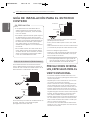
INSTALLATION MANUAL
AIR
CONDITIONER
Please read this installation manual completely before installing the product.
Installation work must be performed in accordance with the national wiring
standards by authorized personnel only.
Please retain this installation manual for future reference after reading it thoroughly.
This product contains Fluorinated Greenhouse Gases. (R410A)
Multi Standard
Original instruction
www.lg.com
ENGLISH ESPAÑOL
PORTUGUÊS
REV.00_012618

Young children should be supervised to ensure that they do not
play with the air conditioner.

IMPORTANT SAFETY INSTRUCTIONS
3
ENGLISH
• Do not modify or extend the power cable. If the power cable or cord
has scrathes or skin peeled off or deteriorated then it must be
replaced. There is risk of fire or electric shock.
• For installation, removal or reinstall , always contact the dealer or an
Authorized Service Center. There is risk of fire, electric shock, explo-
sion, or injury.
• Do not install the product on a defective installation stand. Be sure
that the installation area does not deteriorate with age. It may cause
product to fall.
• Never install the outdoor unit on a moving base or a place from where
it can fall down.
The falling outdoor unit can cause damage or injury or even death of a
person.
• In outdoor unit the step-up capacitor supplies high voltage electricity
to the electrical components. Be sure to discharge the capacitor com-
pletely before conducting the repair work.
An charged capacitor can cause electrical shock.
• When installing the unit, use the installation kit provided with the
product. Otherwise the unit may fall and cause severe injury.
• Indoor/outdoor wiring connections must be secured tightly and the
cable should be routed properly so that there is no force pulling the
cable from the connection terminals. Improper or loose connections
can cause heat generation or fire.
• Safely dispose off the packing materials. Like screws, nails, batteries,
broken things etc after installation or svc and then tear away and
throw away the plastic packaging bags. Children may play with them
and cause injury.
• Be sure to check the refrigerant to be used. Please read the label on
the product. Incorrect refrigerant used can prevent the normal opera-
tion of the unit.
Operation
• When the product is soaked (flooded or submerged) in water , contact
an Authorized Service Center for repair before using it again. There is
risk of fire or eletric shock.
• Be sure to use only those parts which are listed in the svc parts list.
Never attempt to modify the equipment. The use of inappropriate
parts can cause an electrical shock, excessive heat generation or fire.
• Do not touch , operate, or repair the product with wet hands. Hold the
plug by hand when taking out. There is risk of electric shock or fire.
1,MFL68883813,영영 2017. 9. 20. 영영 1:20 Page 3

4
IMPORTANT SAFETY INSTRUCTIONS
ENGLISH
• Do not place a heater or other heating appliances near the power
cable. There is risk of fire and electric shock.
• Do not allow water to run into electric parts. Install the unit away from
water sources. There is risk of fire, failure of the product, or electric
shock.
• Do not store or use or even allow flammable gas or combustibles near
the product. There is risk of fire.
• Do not use the product in a tightly closed space for a long time.
Perform ventilation regularly. Oxygen deficiency could occur and
hence harm your health.
• Do not open the front grille of the product during operation. (Do not
touch the electrostatic filter, if the unit is so equipped.) There is risk of
physical injury, electric shock, or product failure.
• If strange sound, smell or smoke comes from product.Immediately
turn the breaker off or disconnect the power supply cable. There is
risk of electric shock or fire.
• Ventilate the product room from time to time when operating it
together with a stove, or heating element etc. Oxygen deficiency can
occur and hence harm your health.
• When the product is not to be used for a long time, disconnect the
power supply plug or turn off the breaker. There is risk of product
damage or failure, or unintended operation.
• Take care to ensure that nobody especially kids could step on or fall
onto the outdoor unit. This could result in personal injury and product
damage.
• Take care to ensure that power cable could not be pulled out or dam-
aged during operation. There is risk of fire or electric shock.
• Do not place ANYTHING on the power cable. There is risk of fire or
electric shock.
• When flammable gas leaks, turn off the gas and open a window for
ventilation befor turning on the product. Do not use the telephone or
turn switches on or off. There is risk of explosion or fire.
CAUTION
Installation
• Two or more people must lift and transport the product. Avoid person-
al injury.
• Do not install the product where it will be exposed to sea wind (salt
spray) directly. It may cause corrosion on the product.
!
1,MFL68883813,영영 2017. 9. 20. 영영 1:20 Page 4

IMPORTANT SAFETY INSTRUCTIONS
5
ENGLISH
• Install the drain hose to ensure that the condensed water is drained
away properly. A bad connection may cause water leakage.
• Keep level even when installing the product. To avoid vibration or
noise.
• Do not install the product where the noise or hot air from the outdoor
unit could damage or disturb the neighborhoods. It may cause a prob-
lem for your neighbors and hence dispute.
• Always check for gas (refrigerant) leakage after installation or repair of
product. Low refrigerant levels may cause failure of product.
• Please install safely at a place that can sufficiently endure the weight
of the product.
If the strength is not sufficient, the product may fall and cause injury.
Operation
• Do not use the product for special purposes, such as preserving
foods, works of art, etc. It is a consumer air conditioner, not a preci-
sion refrigeration system. There is risk of damage or loss of property.
• Do not block the inlet or outlet of air flow. It may cause product fail-
ure.
• Use a soft cloth to clean. Do not use harsh detergents, solvents or
splashing water etc. There is risk of fire, electric shock, or damage to
the plastic parts of the product.
• Do not touch the metal parts of the product when removing the air fil-
ter. There is risk of personal injury.
• Do not step on or put anyting on the product. (outdoor units) There is
risk of personal injury and failure of product.
• Always insert the filter securely after cleaning. Clean the filter every
two weeks or more often if necessary. A dirty filter reduces the effi-
ciency.
• Do not insert hands or other objects through the air inlet or outlet
while the product is operating. There are sharp and moving parts that
could cause personal injury.
• Be cautious when unpacking and installing the product. Sharp edges
could cause injury.
• If the refrigerant gas leaks during the repair, do not touch the leakaing
refrigerant gas. The refrigernat gas can cause frostbite (cold burn).
• Do not tilt the unit when removing or uninstalling it. The condensed
water inside can spill.
1,MFL68883813,영영 2017. 9. 20. 영영 1:20 Page 5

User must carry routine checkup & cleaning to avoid unit’s poor
performance.In case of special situation, the job must be carried out by
service person only.

TABLE OF CONTENTS
7
ENGLISH
2 IMPORTANT SAFETY
INSTRUCTIONS
8 INSTALLATION
9 INSTALLATION OF
INDOOR, OUTDOOR
UNIT
9 Select the best location
10 Fixing Installation Plate
11 Piping length and elevation
11 Refrigerant charge
12 Drill a hole in the wall
12 INSTALLATION OF
WIRED REMOTE CON-
TROLLER
14 Wired remote controller installation
15 FLARING WORK AND
CONNECTION OF PIPING
15 Flaring work
16 Connection of piping - Indoor
18 Connection of piping - Outdoor
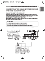
19 CONNECTING THE CABLE
BETWEEN INDOOR UNIT
AND OUTDOOR UNIT
19 Connect the cable to the Indoor unit
21 Connect the cable to the Outdoor unit
23 CHECKING THE
DRAINAGE AND FORM-
ING THE PIPINGS
23 Checking the Drainage
24 Forming the Piping
25 AIR PURGING AND EVAC-
UATION
25 Checking method
26 Evacuation
27 INSTALLATION PI485
28 TEST RUNNING
29 FUNCTION
29 Dip S/W Setting
30 Forced Cooling Operation
31 Wiring Error Check
31 Saving Power Consumption
32 Night Quiet Mode
33 Mode Lock
33 SLC (Smart Load Control) Mode
34 PCB Display(18/24 k Model Only)
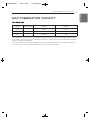
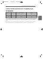
35 MAX COMBINATION
CAPACITY
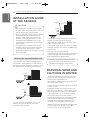
36 INSTALLATION GUIDE AT
THE SEASIDE
36 SEASONAL WIND AND
CAUTIONS IN WINTER
37 Airborne Noise Emission
37 Limiting concentration
TABLE OF CONTENTS
1,MFL68883813,영영 2017. 9. 25. 영영 1:49 Page 7

8
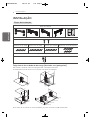
INSTALLATION
ENGLISH
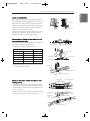
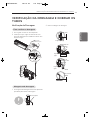
Installation plate
Type "B" screws
Type "A" screw (6 EA) Type "A" screw (8 EA) Type "A" screw (7 EA)
Holder Remote Control
Type "A" screw and plastic anchors
more than
30cm
more than
30cm
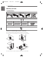
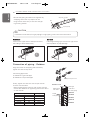
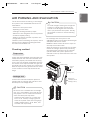
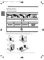
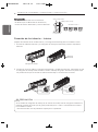
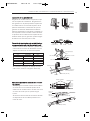
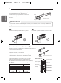
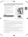
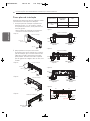
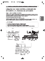
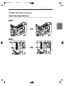
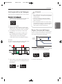
Installation Parts
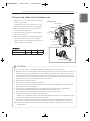
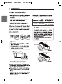
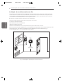
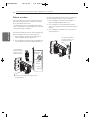
Clearance of side discharge unit [Unit : mm(inch)]
Do not install the product where sufficient ventilation is not secured.
The performance may be decreased or the product may not be operated.
h In case of series or another installation, please refer to related PDB.
300(11-13/16)
or more
300(11-13/16)
300(11-13/16)
0001 (39-3/8) or more
600(23-19/32)
or more
500(19-11/16) or less
or more
or more
L
D
H
erom ro )8/3-93(0001
1000(39-3/8)
or more
500(19-11/16) or less
500(19-11/16) or less
300(11-13/16)
or more
600(23-19/32) or more
1000(39-3/8) or more
2000(78-3/4) or more
300(11-13/16)
or more
500(19-11/16) or less
INSTALLATION
1,MFL68883813,영영 2017. 9. 20. 영영 1:20 Page 8

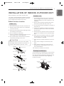
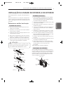
INSTALLATION OF INDOOR, OUTDOOR UNIT
9
ENGLISH
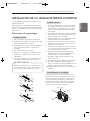
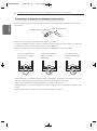
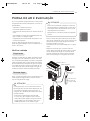
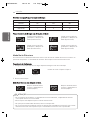
Install the indoor unit on the wall where
the height from the floors more than 2.3
meters. (ART COOL Type Only 1.5m)
CAUTION
!
Read completely, then follow step by step.
You need to select adequate installation location
considering the following conditions, and make
sure to acquire the consent of the user.
Select the best location
1 Do not have any heat or steam near the unit.
2 Select a place where there are no obstacles
in front of the unit.
3 Make sure that condensation drainage can be
conveniently routed away.
4 Do not install near a doorway.
5
Ensure the spaces indicated by arrows from the
wall, ceiling, fence or other obstacles.
6 Use a stud finder to locate studs to prevent
unnecessary damage to the wall.
1 If an awning is built over the unit to prevent
direct sunlight or rain exposure, make sure
that heat radiation from the condenser is not
restricted.
2 Ensure that the spaces indicated by arrows
around front, back and side of the unit.
3 Do not place animals and plants in the path of
the warm air.
4 Take the air conditioner weight into account
and select a place where noise and vibration
are minimum.
5 Select a place so that the warm air and noise
from the air conditioner do not disturb neigh-
bors.
6 Place that can sufficiently endure the weight
and vibration of the outdoor unit and where
even installation is possible.
7 Place that has no direct influence of snow or
rain.
8 Place with no danger of snowfall or icicle
drop.
9 Place without weak floor or base such as
decrepit part of the building or with a lot of
snow accumulation.
10 Sufficient ventilation is secured.
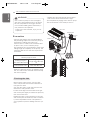
If the outdoor unit is installed on a roof structure,
be sure to level the unit. Ensure the roof struc-
ture and anchoring method are adequate for the
unit location. Consult local codes regarding
rooftop mounting.
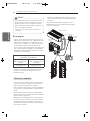
Indoor unit
Outdoor unit
Rooftop Installations
INSTALLATION OF INDOOR, OUTDOOR UNIT
More than 20cm
More than
10cm
More than 2.3m
More than
10cm
More than 20cm
More than
10cm
More than 2.3m
More than
10cm
More than 20cm
More than
10cm
More than 2.3m
More than
10cm
more than
70cm
more than
30cm
more than 60cm
more than
30cm
more than
60cm
1,MFL68883813,영영 2017. 9. 20. 영영 1:20 Page 9

10
INSTALLATION OF INDOOR, OUTDOOR UNIT
ENGLISH
Chassis
Hook
Installation Plate
Type “A”
Installation Plate
Type “A”
65mm
Installation Plate
Chassis
Hook
Type "A" Screws
Unit
Outline
Left Rear
Piping
Right Rear
Piping
Place a level on raised tab
(Unit : mm)
Installation plate
Ø65
Ø65
184
220
156
307
460 567
Chassis
Hook
Installation Plate
Type “A”
Installation plate
Left rear piping Right rear piping
Ø65
Ø65
105mm
105mm
65mm
55mm
45mm
140mm
Ø65
65mm65mm
65mm
45mm
Ø65
Installation plate
Left rear piping Right rear piping
Installation plate
Left rear piping Right rear piping
Ø65
133mm
101mm
101mm
Ø65
100mm
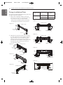
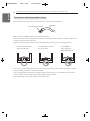
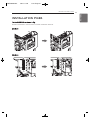
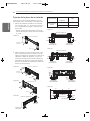
Fixing Installation Plate
The wall you select should be strong and solid
enough to prevent vibration
1 Mount the installation plate on the wall
with type "A" screws. If mounting the unit
on a concrete wall, use anchor bolts.
- Mount the installation plate horizontally
by aligning the centerline using a level.
<Type 1>
2 Measure the wall and mark the centerline.
It is also important to use caution concern-
ing the location of the installation plate-
routing of the wiring to power outlets is
through the walls typically. Drilling the hole
through the wall for piping connections
must be done safely.
<Type 2>
<Type 3>
<Type 4>
<Type 1>
<Type 2>
<Type 3>
<Type 4>
Indoor Type
Capacity
(kBtu/h)
Type
Wall mounted
9, 12 1, 3
18 2, 4
1,MFL68883813,영영 2017. 9. 20. 영영 1:20 Page 10

INSTALLATION OF INDOOR, OUTDOOR UNIT
11
ENGLISH
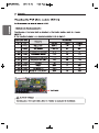
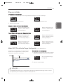
h2
h1
A
B
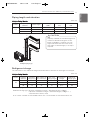
Multiple Piping Type
Capacity is based on standard length and
maximum allowance length is on the
basis of reliability. If outdoor unit is at
higher elevation than the indoor units,
after 24m of vertical height, 1 oil trap is
required.
CAUTION
!
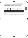
• Multiple Piping Models
Additional charge (g) = ((A Room Installation Length – Standard Length ) x 20g/m
+ (B Room Installation Length – Standard Length ) x 20g/m +.. )
- CF(Correction Factor) x 150
h CF = Max. number of connectable indoor unit – Total number of connected indoor unit
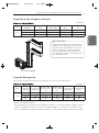
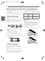
Refrigerant charge
The calculation of the additional charge should be taken in account for the length of extra pipe.
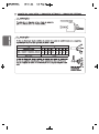
Multiple Piping Models (Unit: m)
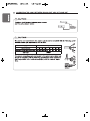
Piping length and elevation
Multiple Piping Models (Unit: m)
Phase
Capacity
(kBtu/h)
Total Length
Max Length
(A/B)
Max Elevation
(h1)
In-In Elevation
(h2)
1Ø
18 30 20 15 7.5
24 50 25 15 7.5
36 75 25 15 7.5
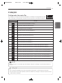
Phase
Capacity
(kBtu/h)
Standard
Length (m)
Max Piping for
one room (m)
Max total
Piping Length
Chargeless
Length
Additional
Charge (g/m)
1Ø
18 7.5 20 30 20 20
24 7.5 25 50 22.5 20
36 7.5 25 75 37.5 20
1,MFL68883813,영영 2017. 9. 20. 영영 1:20 Page 11

12
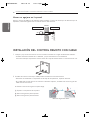
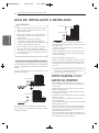
INSTALLATION OF WIRED REMOTE CONTROLLER
ENGLISH
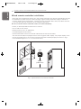
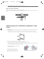
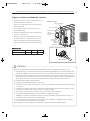
1 Please fix tightly using provided screw after placing remote controller setup board on the
place where you like to setup.
- Please set it up not to bend because poor setup could take place if setup board bends.
Please set up remote controller board fit to the reclamation box if there is a reclamation box.
2 Can set up Wired remote controller cable into three directions.
- Setup direction: the surface of wall reclamation, upper, right
- If setting up remote controller cable into upper and right side, please set up after removing
remote controller cable guide groove.
h Remove guide groove with long nose.
① Reclamation to the surface of the wall
② Upper part guide groove
③ Right part guide groove
2
2
1
3
3
<Wire guide grooves>
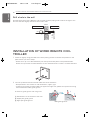
INSTALLATION OF WIRED REMOTE CON-
TROLLER
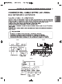
Drill a hole in the wall
Drill the piping hole with a Ø65mm hole core drill. Drill the piping hole at either the right or the
left with the hole slightly slanted to the outdoor side.
5-7mm
(3/16"~5/16")
Indoor
WALL
Outdoor
1,MFL68883813,영영 2017. 9. 20. 영영 1:20 Page 12

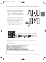
INSTALLATION OF WIRED REMOTE CONTROLLER
13
ENGLISH
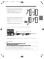
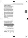
4 Please connect indoor unit and remote controller using connection cable.
5 Please use extension cable if the distance between wired remote controller and indoor unit is
more than 10m.
Please check if connector is normally connected.
Connecting cable
Indoor
Unit side
When installing the wired remote controller, do not bury it in the wall.
(It can cause damage in the temperature sensor.)
Do not install the cable to be 50m or above.
(It can cause communication error.)
• When installing the extension cable, check the connecting direction of the connector of
the remote controller side and the product side for correct installation.
• If you install the extension cable in the opposite direction, the connector will not be con-
nected.
• Specification of extension cable: 2547 1007 22# 2 core 3 shield 5 or above.
CAUTION
!
3 Please fix remote controller upper part into the
setup board attached to the surface of the wall,
as the picture below, and then, connect with
setup board by pressing lower part.
- Please connect not to make a gap at the remote
controller and setup board’s upper and lower,
right and left part.
When separating remote controller from setup
board, as the picture below, after inserting into
the lower separating hole using screw driver and
then, spinning clockwise, remote controller is
separated.
- There are two separating holes. Please individu-
ally separate one at a time.
- Please be careful not to damage the inside
components when separating.
Wall
Side
Wall
Side
Wall
Side
Wall
Side
<Connecting order>
<Separating order>
1,MFL68883813,영영 2017. 9. 20. 영영 1:20 Page 13

14
INSTALLATION OF WIRED REMOTE CONTROLLER
ENGLISH
5feet
(1.5meters)
no
no
no
yes
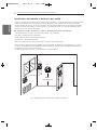
Fig.1 Typical locations for remote controller
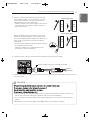
Wired remote controller installation
- Since the room temperature sensor is in the remote controller, the remote controller box should
be installed in a place away from direct sunlight, high humidity and direct supply of cold air to
maintain proper space temperature. Install the remote controller about 5ft(1.5m) above the floor
in an area with good air circulation at an average temperature.
Do not install the remote controller where it can be affected by:
- Drafts, or dead spots behind doors and in corners.
- Hot or cold air from ducts.
- Radiant heat from sun or appliances.
- Concealed pipes and chimneys.
- Uncontrolled areas such as an outside wall behind the remote controller.
- This remote controller is equipped with a seven segment LED. display. For proper display of the
remote controller LED's, the remote controller should be installed properly as shown in Fig.1.
(The standard height is 1.2~1.5 m from floor level.)
1,MFL68883813,영영 2017. 9. 20. 영영 1:20 Page 14

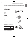
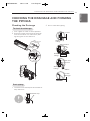
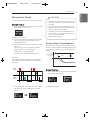
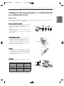
FLARING WORK AND CONNECTION OF PIPING
15
ENGLISH
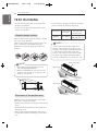
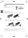
Cut the pipes and the cable
- Use the piping kit accessory or the pipes pur-
chased locally.
- Measure the distance between the indoor
and the outdoor unit.
- Cut the pipes a little longer than measured
distance.
- Cut the cable 1.5m longer than the pipe
length.
Burrs removal
- Completely remove all burrs from the cut
cross section of pipe/tube.
- Put the end of the copper tube/pipe in a
downward direction as you remove burrs in
order to avoid dropping burrs into the tubing.
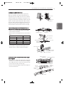
Putting nut on
- Remove flare nuts attached to indoor and
outdoor unit, then put them on pipe/tube
having completed burr removal.
(not possible to put them on after flaring
work)
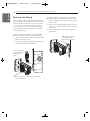
Flaring work
- Carry out flaring work using flaring tool as
shown below.
Firmly hold copper pipe in a bar in the
dimension shown in the table below.
Copper
tube
90°
Slanted Uneven Rough
Pipe
Reamer
Point down
Flare nut
Copper tube
Bar
Copper pipe
Clamp handle
Red arrow mark
Cone
Yoke
Handle
Bar
"A"
Outside diameter
A
mm inch mm
Ø6.35 1/4 1.1~1.3
Ø9.52 3/8 1.5~1.7
Ø12.7 1/2 1.6~1.8
Ø15.88 5/8 1.6~1.8
Ø19.05 3/4 1.9~2.1
Flaring work
Main cause for gas leakage is due to defect in flaring work. Carry out correct flaring work in the
following procedure.
FLARING WORK AND CONNECTION OF PIPING
1,MFL68883813,영영 2017. 9. 20. 영영 1:20 Page 15

16
FLARING WORK AND CONNECTION OF PIPING
ENGLISH
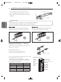
Inclined
Inside is shining without scratches.
Smooth all round
Even length
all round
Surface
damaged
Cracked Uneven
thickness
= Improper flaring =
Connecting
pipe
Connecting cable
Tape
Drain hose
Connecting
pipe
Connecting cable
Tape
Drain hose
If the drain hose is routed inside the room, insulate the hose with an insulation material* so
that dripping from "sweating"(condensation) will not damage furniture or floors.
*Foamed polyethylene or equivalent is recommended.
CAUTION
!
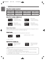
Check
- Compare the flared work with figure below.
- If flare is noted to be defective, cut off the
flared section and do flaring work again.
Connection of piping - Indoor
Preparing the indoor unit's piping and drain hose for installation through the wall.
1 Route the indoor tubing and the drain hose in the direction of rear left or right
2 Tape the tubing, drain hose and the connecting cable. Be sure that the drain hose is located at
the lowest side of the bundle. Locating at the upper side can cause drain pan to overflow
inside the unit.
Drain hose
Drain hose
1,MFL68883813,영영 2017. 9. 20. 영영 1:20 Page 16

FLARING WORK AND CONNECTION OF PIPING
17
ENGLISH
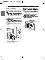
Indoor unit installation
Hook the indoor unit onto the upper portion of
the installation plate.(Engage the two hooks of
the rear top of the indoor unit with the upper
edge of the installation plate.) Ensure that the
hooks are properly seated on the installation
plate by moving it left and right.
Press the lower left and right sides of the unit
against the installation plate until the hooks
engage into their slots(clicking sound).
Connecting the pipings to the indoor unit and
drain hose to drain pipe
- Align the center of the pipings and sufficient-
ly tighten the flare nut by hand.
- Tighten the flare nut with a wrench.
- When extending the drain hose at the indoor
unit, install the drain pipe.
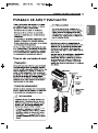
Wrap the insulation material around the con-
necting portion.
- Overlap the connection pipe insulation mate-
rial and the indoor unit pipe insulation materi-
al. Bind them together with vinyl tape so that
there is no gap.
- Wrap the area which accommodates the rear
piping housing section with vinyl tape.
Drain hose
Connecting
Indoor unit tubing
Flare nut
Pipings
Torque wrench
Indoor unit tubing
Spanner (fixed)
Connection pipe
Flare nut
Vinyl tape(narrow)
Adhesive
Drain pipe
Indoor unit drain hose
Plastic bands
Insulation material
Vinyl tape(narrow)
Connection
pipe
Connecting cable
Vinyl tape
(wide)
Wrap with vinyl tape
Indoor
unit pipe
Pipe
Outside diameter.
Torque
mm inch N
.
m
Ø6.35 1/4 16±2
Ø9.52 3/8 38±4
Ø12.7 1/2 55±6
Ø15.88 5/8 75±7
Ø19.05 3/4 110±10
1,MFL68883813,영영 2017. 9. 20. 영영 1:20 Page 17

18
FLARING WORK AND CONNECTION OF PIPING
ENGLISH
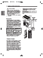
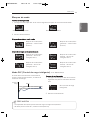
- Bundle the piping and drain hose together by
wrapping them with vinyl tape over the
range within which they fit into the rear pip-
ing housing section.
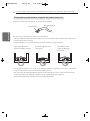
Good case
Press on the upper side of clamp and unfold
the tubing to downward slowly.
Bad case
Following bending type from left to right could
cause problem of pipe damage.
Wrap with vinyl tape
Drain hose
Pipe
Vinyl tape(wide)
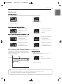
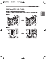
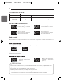
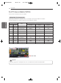
Ø12.7(1/2 inch) Connector
Outdoor unit
Main gas
side valve
Main liquid
side valve
Gas side piping
ROOM A
ROOM B
ROOM C
ROOM D
ROOM E
Liquid
side piping
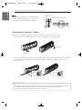
Installation Information (For right piping) For right piping, follow the instruction below.
CAUTION
!
Outside diameter
Torque
mm inch N
.
m
Ø6.35 1/4 16±2
Ø9.52 3/8 38±4
Ø12.7 1/2 55±6
Ø15.88 5/8 75±7
Ø19.05 3/4 110±10
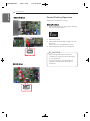
Connection of piping - Outdoor
Align the center of the piping and sufficiently
tighten the flare nut by hand.
Connecting pipe order
1) ROOM A~E gas side pipe
2) ROOM A~E liquid side pipe
Finally, tighten the flare nut with torque wrench
until the wrench clicks.
- When tightening the flare nut with torque wrench
ensure the direction for tightening follows the arrow
on the wrench.
1,MFL68883813,영영 2017. 9. 20. 영영 1:20 Page 18

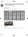
18 K
36 K
24 K
D
D

A página está carregando ...
A página está carregando ...
A página está carregando ...
A página está carregando ...
A página está carregando ...
A página está carregando ...
A página está carregando ...
A página está carregando ...
A página está carregando ...
A página está carregando ...
A página está carregando ...
A página está carregando ...
A página está carregando ...
A página está carregando ...
A página está carregando ...
A página está carregando ...
A página está carregando ...
A página está carregando ...
A página está carregando ...
A página está carregando ...
A página está carregando ...
A página está carregando ...
A página está carregando ...
A página está carregando ...
A página está carregando ...
A página está carregando ...
A página está carregando ...
A página está carregando ...
A página está carregando ...
A página está carregando ...
A página está carregando ...
A página está carregando ...
A página está carregando ...
A página está carregando ...
A página está carregando ...
A página está carregando ...
A página está carregando ...
A página está carregando ...
A página está carregando ...
A página está carregando ...
A página está carregando ...
A página está carregando ...
A página está carregando ...
A página está carregando ...
A página está carregando ...
A página está carregando ...
A página está carregando ...
A página está carregando ...
A página está carregando ...
A página está carregando ...
A página está carregando ...
A página está carregando ...
A página está carregando ...
A página está carregando ...
A página está carregando ...
A página está carregando ...
A página está carregando ...
A página está carregando ...
A página está carregando ...
A página está carregando ...
A página está carregando ...
A página está carregando ...
A página está carregando ...
A página está carregando ...
A página está carregando ...
A página está carregando ...
A página está carregando ...
A página está carregando ...
A página está carregando ...
A página está carregando ...
A página está carregando ...
A página está carregando ...
A página está carregando ...
A página está carregando ...
A página está carregando ...
A página está carregando ...
A página está carregando ...
A página está carregando ...
A página está carregando ...
A página está carregando ...
A página está carregando ...
A página está carregando ...
A página está carregando ...
A página está carregando ...
A página está carregando ...
A página está carregando ...
A página está carregando ...
A página está carregando ...
A página está carregando ...
A página está carregando ...
A página está carregando ...
A página está carregando ...
A página está carregando ...
A página está carregando ...
A página está carregando ...
A página está carregando ...
-
 1
1
-
 2
2
-
 3
3
-
 4
4
-
 5
5
-
 6
6
-
 7
7
-
 8
8
-
 9
9
-
 10
10
-
 11
11
-
 12
12
-
 13
13
-
 14
14
-
 15
15
-
 16
16
-
 17
17
-
 18
18
-
 19
19
-
 20
20
-
 21
21
-
 22
22
-
 23
23
-
 24
24
-
 25
25
-
 26
26
-
 27
27
-
 28
28
-
 29
29
-
 30
30
-
 31
31
-
 32
32
-
 33
33
-
 34
34
-
 35
35
-
 36
36
-
 37
37
-
 38
38
-
 39
39
-
 40
40
-
 41
41
-
 42
42
-
 43
43
-
 44
44
-
 45
45
-
 46
46
-
 47
47
-
 48
48
-
 49
49
-
 50
50
-
 51
51
-
 52
52
-
 53
53
-
 54
54
-
 55
55
-
 56
56
-
 57
57
-
 58
58
-
 59
59
-
 60
60
-
 61
61
-
 62
62
-
 63
63
-
 64
64
-
 65
65
-
 66
66
-
 67
67
-
 68
68
-
 69
69
-
 70
70
-
 71
71
-
 72
72
-
 73
73
-
 74
74
-
 75
75
-
 76
76
-
 77
77
-
 78
78
-
 79
79
-
 80
80
-
 81
81
-
 82
82
-
 83
83
-
 84
84
-
 85
85
-
 86
86
-
 87
87
-
 88
88
-
 89
89
-
 90
90
-
 91
91
-
 92
92
-
 93
93
-
 94
94
-
 95
95
-
 96
96
-
 97
97
-
 98
98
-
 99
99
-
 100
100
-
 101
101
-
 102
102
-
 103
103
-
 104
104
-
 105
105
-
 106
106
-
 107
107
-
 108
108
-
 109
109
-
 110
110
-
 111
111
-
 112
112
-
 113
113
-
 114
114
-
 115
115
-
 116
116


LG A2UW18GFAB Manual do proprietário
- Categoria
- Condicionadores de ar de sistema split
- Tipo
- Manual do proprietário
- Este manual também é adequado para
em outros idiomas
- español: LG A2UW18GFAB El manual del propietario
- English: LG A2UW18GFAB Owner's manual
Artigos relacionados
-
LG MS09AWW Guia de instalação
-
LG MS18AWW Guia de instalação
-
LG ATNW60GMLP0.ANWZBRZ Guia de instalação
-
-
LG PM07SP.NSJ Guia de instalação
-
LG FM48AH Guia de instalação
-
-
-
LG ARNU24GTLC4 Manual do usuário
-
LG ARNU12GSBL4 Manual do usuário
Outros documentos
-
Mitsubishi MSZ-DM35VA Manual do proprietário
-
Mitsubishi Electric KOMPAKT MXZ-2D33VA Guia de instalação
-
-
-
Carrier Split-type Room Air Conditioner Manual do proprietário
-
-
-
Sharp AE-A12NR Instruções de operação
-
Sanyo SPW-XR254EH56 Manual do usuário
-