
ENGLISH
INSTALLATION AND USER’S MANUAL
SPANISH
MANUAL DE INSTALACIÓN Y USO
POLSKI
INSTRUKCJA OBSŁUGI I INSTALACJI
SERBIAN
INSTALACIJA I UPUTSTVO ZA UPOTREBU
PORTUGUÊS
MANUAL DE INSTALAÇÃO E UTILIZADOR
DEUTSCH
INSTALLATIONS- UND BEDIENUNGSANLEITUNG
БЪЛГАРСКИ
РЪКОВОДСТВО ЗА МОНТАЖ И ЕКСПЛОАТАЦИЯ

INSTALLATION AND USER’S MANUAL
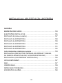
CONTENT
INTRODUCTION
03
SAFETY PRECAUTION
03
ELECTRICAL INSTALLATION
05
SPECIFICATION
06
INSTALLATION (VENT OUTSIDE)
07
INSTALLATION (VENT INSIDE)
11
DESCRIPTION OF COMPONENTS
16
OPERATION
17
MAINTENANCE
19
TROBULESHOOTING
20
CONFORMITY WITH DIRECTIVES
20
ENVIRONMENTAL PROTECTION
21
2

INTRODUCTION
Thank you for choosing this cooker hood.
This instruction manual is designed to provide you with all required
instructions related to the installation, use and maintenance of the appliance.
In order to operate the unit correctly and safety, please read this instruction
manual carefully before installation and usage.
The cooker hood uses high quality materials, and is made with a streamlined
design. Equipped with large power electric motor and centrifugal fan, it also
provides strong suction power, low noise operation, non-stick grease filter and
easy assembly installation.
By placing the
marking on this product, we declare, on our own
responsibility, compliance to all of European safety, health and environmental
requirements stated in the legislation for this product.
SAFETY PRECAUTION
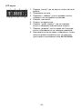
� Never let the children operate the machine.
� The cooker hood is for home use only, not suitable for barbecue, roast
shop and other commercial purpose.
� The cooker hood and its filter should be clean regularly in order to keep in
good working condition.
� Clean the cooker hood according to the instruction manual and keep the
unit from danger of burning.
� Forbid the direct baking from the gas cooker. Please keep the kitchen
room a good convection.
� Before connecting this appliance check that the power supply cord is not
damaged. A damage supply cord must be replaced by qualified service
personnel only.
� There shall be adequate ventilation of the room when the range hood is
used at the same time as appliances burning gas or other fuels;
� The air must not be discharged into a flue that is used for exhausting
fumes from appliances burning gas or other fuels;
� Regulations concerning the discharge of air have to be fulfilled.
� Children should be supervised to ensure that they do not play with the
appliance.
� Do not flambé under the range hood.
� The range hood is not intended to be installed over a hob having more
than four hob elements
3

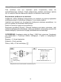
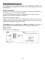
Electrical Shock Hazard
Only plug this unit into a properly earthed outlet. If in doubt seek advice
from a suitably qualified engineer.
Failure to follow these instructions can result in death, fire, or electrical
shock.
5IFTFTIBMMCFBEFRVBUFWFOUJMBUJPOPGUIFSPPNXIFOUIFSBOHF
IPPEJTVTFEBUUIFTBNF UJNFBTBQQMJBODFTCVSOJOHHBTPSPUIFS
GVFMTOPUBQQMJDBCMFUPBQQMJBODFTUIBUPOMZEJTDIBSHFUIFBJSCBDL
JOUPUIFSPPN
UIFEFUBJMTDPODFSOJOHUIFNFUIPEBOEGSFRVFODZPGDMFBOJOH
UIFSFJTBGJSFSJTLJGDMFBOJOHJTOPUDBSSJFEPVUJOBDDPSEBODFXJUIUIF
JOTUSVDUJPOT
EPOPUGMBNFVOEFSUIFSBOHFIPPE
$"65*0/"DDFTTJCMFQBSUTNBZCFDPNFIPUXIFOVTFEXJUI
DPPLJOHBQQMJBODFT
�
�
4

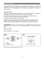
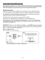
Electrical Installation
All installation must
be carried out by a competent person or qualified
electrician. Before connecting the mains supply ensure that the mains
voltage corresponds to the voltage on the rating plate.
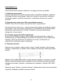
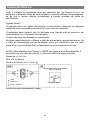
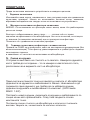
Direct Connection
The appliance must be connected directly to the mains using an omnipolar
circuit breaker with a minimum opening of 3mm between the contacts.
The installer must ensure that the correct electrical connection has been
made and that it complies with the wiring diagram.
The cable must not be bent or compressed.
Regularly check the power plug and power cord for damage. If the supply
cord is damaged, it must be replaced by a special cord or assembly
available from the manufacturer or its service agent.
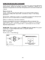
WARNING: This i
s a Class I appliance and MUST be earthed This
appliance is supplied with a 3 core mains cable coloured as follows:
Brown = L or Live
Blue = N or Neutral
Green and Yellow = E or Earth
The fuse must be rated at 3 Amps.
5

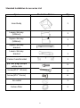
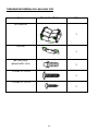
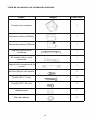
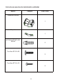
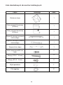
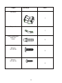
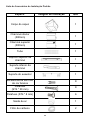
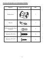
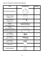
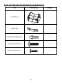
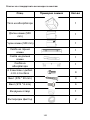
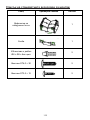
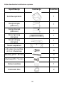
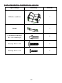
Standard Installation Accessories List
Spec.
Illustration Picture
Qty
Hood body 1
Lower chimney
(500mm)
1
Upper chimney
(500mm)
1
Upper chimney
bracket
1
Lower chimney
bracket
1
Cooker hood bracket 1
φ8 rawl plugs φ8×φ6
white color
9
Screw (ST4 * 8 mm)
9
Screw (ST4 * 30 mm)
6
Air outlet
1
Carbon filter 2
6

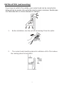
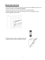
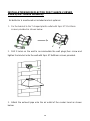
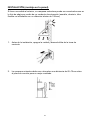
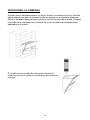
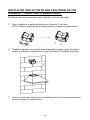
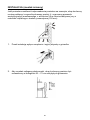
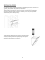
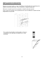
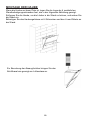
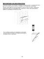
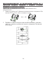
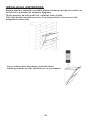
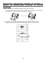
INSTALLATION (wall mounting)
If you have an outlet to the outside, your cooker hood can be connected as
below picture by means of an extraction duct (enamel, aluminum, flexible pipe
non flammabe with an interior diameter of 150mm)
1. Before installation, turn the unit off and unplug it from the outlet.
2. The cooker hood should be placed at a distance of 65~75c
m above
the cooking plane for best effect.
7

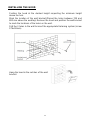
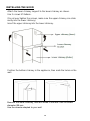
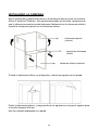
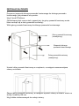
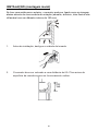
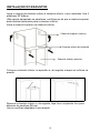
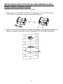
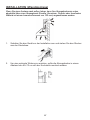
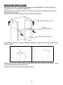
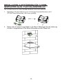
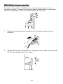
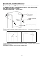
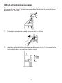
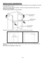
INSTALLING THE HOOD
Position the hood at the desired hei
ght respecting the minimum height
above the hob.
Mark the location of the wall bracket.(Placed the holes between 700 and
800 mm above the worktop) Remove the hood and position the wall bracket
to mark the locations of the holes on the wall.
Drill the 3 holes in the wall to insert the appropriate fastening system (screw
ST4x30mm)..
Hang the hood in the notch
es of the wall
bracket.
8

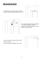
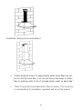
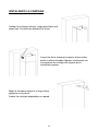
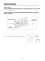
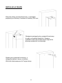
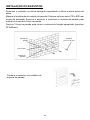
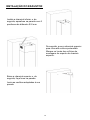
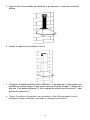
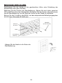
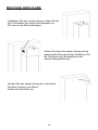
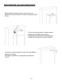
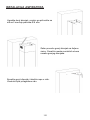
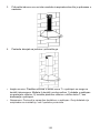
INSTALLING THE HOOD
Once the hood is in place, locate the location of the 4 additional wall mount
screws as shown in the following diagram.
Remove the hood to puncture the wall and install wall plugs.
Secure the body of the hood with 4 screws of 4 mm in diameter using
dowels adapted to your wall.
If the extraction mod
e is selected, place the
exhaust air duct on the air outlet as shown.
9

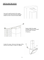
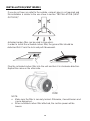
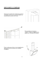
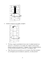
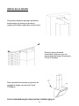
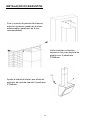
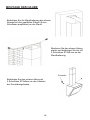
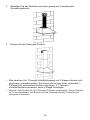
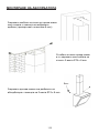
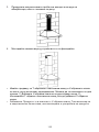
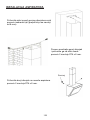
INSTALLING THE HOOD
Attach the lower chimney support to the lower chimney as shown.
Use 2 screws ST4x8mm.
(Do not over tighten the screws, make sure the upper chimney can slide
easily into the lower chimney)
Insert the upper chimney into the lower chimney.
Position the bottom chi
mney in the appliance, then mark the holes on the
wall.
Remove the lower chimney, then drill holes in the wall: hole for screw
diameter Φ8 mm
Use the dowels adapted to your wall
10

INSTALLING THE HOOD
Install the lower chi
mney, then screw it to
the wall with 2 screws of diameter Φ 8 mm
Then pull the upper chimney upwards
to the desired height. Mark the
locations of the mounting holes of the
upper chimney support.
Lower the upper chimney
and then drill
holes in the wall.
Insert the dowels adapted to your wall
11

INSTALLING THE HOOD
Secure the wall bracket of the upper
chimney to the wall using the selected
dowels (8 mm screws recommended).
Reassemble the upper
chimney and fix it to the wall
bracket with 2 screws
ST4x8mm
Fasten the lower chimney to the lugs of the
kitchen hood using 2 screws ST4x8mm.
12

Standard Installation Accessories List
Spec. Illustration Picture Qty
Air Deflector
1
Bracket
1
φ8 rawl plugs
φ8×φ6 white color
2
Screws
ST4.0×30
2
Screws
ST3.5×12
2
13

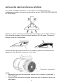
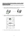
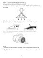
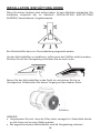
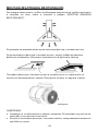
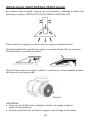
INSTALLATION(AIR DEFLECTOR FOR T-SHAPE,CURVED
GLASS,FLAT GLASS MODELS):
Air deflector is mentioned as included and not optional.
1. Fix the bracket to the T-shaped plastic o
utlet with 2pcs ST3.5x12mm
screws provided as shown below:
2. Drill 2 holes on the wall to accommodate the wall plugs,then screw and
tighten the bracket onto the wall with 2pcs ST4x30mm screws provided.
3. Attach the exhaust pipe onto the air o
utlet of the cooker hood as shown
below:
14

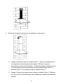
4. Install the chimney to the unit and fix it.
o “Please kindly be noted: T-sha
ped plastic outlet and v-flaps can not
be use d at the same time. You can use them in two ways: 1) Add v-
flap on existing o utlet; 2) Use T-shaped plastic outlet, no add v-flap.”
o “Note: The product is prov
ided with v-flap accessory. This accessory
is not mandatory for installation, operation a
nd
use of the product.”
15

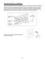
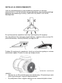
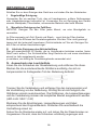
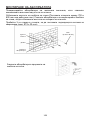
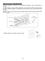
INSTALLATION (VENT INSIDE)
If you do not have an outlet to the outside, exhaust pipe is not required and
the installation is similar to the one show in section “INSTALLATION (VENT
OUTSIDE)”.
Activated carbon filter can
be used to trap odors.
In order to install the activated carbon filter, the grease filter should be
detached first. Press the lock and pull it downward.
Plug the activated carbon filter into the unit and turn it in clockwise direction.
Repeat the same on the other side.
NOTE:
o Make sure the filter is securely locked. Otherwise, it would loosen and
cause dangerous.
o When activated carbon filter attached, the suction power will be
lowere
16

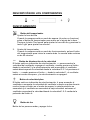
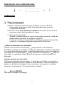
DESCRIPTION OF COMPONENTS
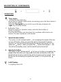
OPERATION
Timer button
1. Setting the time of the day
When hood in standby mode (motor not working), press the timer button to
enter the time setting.
Press the ‘Fan speed’ key to set the hour of the day and press the
‘Light ‘key to set the minute.
2. Setting the Timer
When the hood is in operation mode, press the timer button to
set the countdown.
Press the timer button one timer then the countdown will increase one
minute. The max countdown is 60 minutes.
Speed decrease button
The button is with indicate backlit, - for increasing the speed of the fan
or turn off the fan; when you press the button from speed 3 and the
backlit is on, the fan will be decreasing the speed from speed 3-2-1 by
press the - button, when you press the - button from speed 1, the
fan will be in standby mode. and the backlit will be turned off.
Speed plus button
The button is with indicate backlit, + for turn on the fan or increasing the
speed of the fan when you long press the button at standby mode, the
backlit will be turned on and the fan will be turned on at low speed. then
the fan will be increasing the speed from speed 1-2-3 by press the +
button
LIGHT Button
For lighting ON & OFF.
17

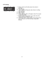
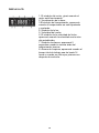
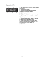
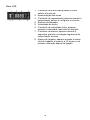
1. Motor symbol, will rotate when the motor is
working;
2. Time display;
3. Timer symbol, will appear when timer is setting
and counting;
4. Light symbol;
5. Motor speed;
6. Turbo speed symbol, will appear when the speed
is highest setted;
7. Alarm symbol, will appear 5 seconds when the
counting down of timer is over.
8. Cleanning alarm, appear when total working time
up to 14 hours or at the first time using after
pluging.
LCD display
18

MAINTENANCE
Before cleaning switch the unit off and pull out the plug.
I. Regular Cleaning
Use a soft c
loth moistened with hand-warm mildly soapy water or
household cleaning detergent. Never use metal pads, chemical, abrasive
material or stiff brush to clean the unit.
II. Monthly Cleaning for Gr
ease Filter
ESSENTIAL: Clean the filter every month can prevent any risk of fire.
The filter collects grease, smoke and dus
t…... so the filter is directly
affecting the efficiency of the cooker hood. If not cleaned, the grease
residue (potential flammable) will saturate on the filter. Clean it with
household cleaning detergent.
III. Annual Cleaning for Activated Carbon Filter
Apply SOLELY to unit that installed as a recirculation unit (not vented to
the outside). This filter traps odors and must be replaced at least once a
year
depending on how frequent the cooker hood used.
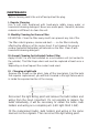
IV. Changing a light bulb
Remove the screws on the glass, take off the hood glass. Find the bulb
that requires replacement, you will find it located in the light fixture which
is inside the exposed section of the canopy.
Disconnect the light wiring point and remove the bulb holders and
wiring from the hood. Important: It’s not possible to replace the
bulbs individually, it will be necessary to obtain the bulbs, bulb
holders and wiring as a complete part. (LED light: MAX 1.5W)
Fit the replacement bulbs, bulb holders and wiring in the same
manners as the originals. Then reconnect the light wiring point.
19

Refit the hood glass and fasten the glass screws. Make sure the screws
are fully tightened.
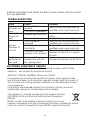
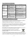
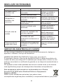
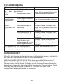
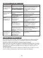
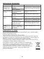
TROBULESHOOTING
Fault
Cause
Solution
Light on, but
fan does not
work
The fan blade is
jammed.
Switch off the unit and repair by
qualified service personnel only.
The motor is damaged.
Both light and
fan do not
work
Halogen light bulb burn.
Replace the bulb with correct
rating.
Power cord looses.
Plug in to the power supply again.
Serious
Vibration of
the unit
The fan blade is
damaged.
Switch of the unit and repair by
qualified service personnel only.
The fan motor is not
fixed tightly.
Switch off the unit and repair by
qualified service personnel only.
The unit is not hung
properly on the bracket.
Take down the unit and check
whether the bracket is in proper
location.
Suction
performance
not good
Too long distance
between the unit and
the cooking plane
Readjust the distance to 65-75cm
CUSTOMER ASSISTANCE SERVICE
If you cannot identify the cause of the operating anomaly, switch off the
appliance and contact the Assistance Service.
PRODUCT SERIAL NUMBER. Where can I find it?
It is important you to inform the Assistance Service of your product code
and its serial number (a 16 character code which begins with the number 3);
this can be found on the guarantee certificate or on the data plate located
on the appliance.
It will help to avoid wasted journeys to technicians, thereby (and most
significantly) saving the corresponding callout charges.
This appliance is marked acc
ording to the European directive
2012/19/EU on Waste Electrical and Electronic Equipment
(WEEE).
WEEE contains both polluting substances (which can cause
negative consequences for the environment) and basic components (which
can be re-used). It is important to have WEEE subjected to specific
20
A página está carregando...
A página está carregando...
A página está carregando...
A página está carregando...
A página está carregando...
A página está carregando...
A página está carregando...
A página está carregando...
A página está carregando...
A página está carregando...
A página está carregando...
A página está carregando...
A página está carregando...
A página está carregando...
A página está carregando...
A página está carregando...
A página está carregando...
A página está carregando...
A página está carregando...
A página está carregando...
A página está carregando...
A página está carregando...
A página está carregando...
A página está carregando...
A página está carregando...
A página está carregando...
A página está carregando...
A página está carregando...
A página está carregando...
A página está carregando...
A página está carregando...
A página está carregando...
A página está carregando...
A página está carregando...
A página está carregando...
A página está carregando...
A página está carregando...
A página está carregando...
A página está carregando...
A página está carregando...
A página está carregando...
A página está carregando...
A página está carregando...
A página está carregando...
A página está carregando...
A página está carregando...
A página está carregando...
A página está carregando...
A página está carregando...
A página está carregando...
A página está carregando...
A página está carregando...
A página está carregando...
A página está carregando...
A página está carregando...
A página está carregando...
A página está carregando...
A página está carregando...
A página está carregando...
A página está carregando...
A página está carregando...
A página está carregando...
A página está carregando...
A página está carregando...
A página está carregando...
A página está carregando...
A página está carregando...
A página está carregando...
A página está carregando...
A página está carregando...
A página está carregando...
A página está carregando...
A página está carregando...
A página está carregando...
A página está carregando...
A página está carregando...
A página está carregando...
A página está carregando...
A página está carregando...
A página está carregando...
A página está carregando...
A página está carregando...
A página está carregando...
A página está carregando...
A página está carregando...
A página está carregando...
A página está carregando...
A página está carregando...
A página está carregando...
A página está carregando...
A página está carregando...
A página está carregando...
A página está carregando...
A página está carregando...
A página está carregando...
A página está carregando...
A página está carregando...
A página está carregando...
A página está carregando...
A página está carregando...
A página está carregando...
A página está carregando...
A página está carregando...
A página está carregando...
A página está carregando...
A página está carregando...
A página está carregando...
A página está carregando...
A página está carregando...
A página está carregando...
A página está carregando...
A página está carregando...
A página está carregando...
A página está carregando...
A página está carregando...
A página está carregando...
A página está carregando...
A página está carregando...
A página está carregando...
A página está carregando...
A página está carregando...
-
 1
1
-
 2
2
-
 3
3
-
 4
4
-
 5
5
-
 6
6
-
 7
7
-
 8
8
-
 9
9
-
 10
10
-
 11
11
-
 12
12
-
 13
13
-
 14
14
-
 15
15
-
 16
16
-
 17
17
-
 18
18
-
 19
19
-
 20
20
-
 21
21
-
 22
22
-
 23
23
-
 24
24
-
 25
25
-
 26
26
-
 27
27
-
 28
28
-
 29
29
-
 30
30
-
 31
31
-
 32
32
-
 33
33
-
 34
34
-
 35
35
-
 36
36
-
 37
37
-
 38
38
-
 39
39
-
 40
40
-
 41
41
-
 42
42
-
 43
43
-
 44
44
-
 45
45
-
 46
46
-
 47
47
-
 48
48
-
 49
49
-
 50
50
-
 51
51
-
 52
52
-
 53
53
-
 54
54
-
 55
55
-
 56
56
-
 57
57
-
 58
58
-
 59
59
-
 60
60
-
 61
61
-
 62
62
-
 63
63
-
 64
64
-
 65
65
-
 66
66
-
 67
67
-
 68
68
-
 69
69
-
 70
70
-
 71
71
-
 72
72
-
 73
73
-
 74
74
-
 75
75
-
 76
76
-
 77
77
-
 78
78
-
 79
79
-
 80
80
-
 81
81
-
 82
82
-
 83
83
-
 84
84
-
 85
85
-
 86
86
-
 87
87
-
 88
88
-
 89
89
-
 90
90
-
 91
91
-
 92
92
-
 93
93
-
 94
94
-
 95
95
-
 96
96
-
 97
97
-
 98
98
-
 99
99
-
 100
100
-
 101
101
-
 102
102
-
 103
103
-
 104
104
-
 105
105
-
 106
106
-
 107
107
-
 108
108
-
 109
109
-
 110
110
-
 111
111
-
 112
112
-
 113
113
-
 114
114
-
 115
115
-
 116
116
-
 117
117
-
 118
118
-
 119
119
-
 120
120
-
 121
121
-
 122
122
-
 123
123
-
 124
124
-
 125
125
-
 126
126
-
 127
127
-
 128
128
-
 129
129
-
 130
130
-
 131
131
-
 132
132
-
 133
133
-
 134
134
-
 135
135
-
 136
136
-
 137
137
-
 138
138
-
 139
139
-
 140
140
-
 141
141


Haier HADG9DCS56B Manual do usuário
- Tipo
- Manual do usuário
- Este manual também é adequado para
em outras línguas
- español: Haier HADG9DCS56B Manual de usuario
- English: Haier HADG9DCS56B User manual
- Deutsch: Haier HADG9DCS56B Benutzerhandbuch
- polski: Haier HADG9DCS56B Instrukcja obsługi
Artigos relacionados
Outros documentos
-
Candy CFT62/3X-ALG Manual do usuário
-
Infiniton CMPTRAL-N68 Manual do proprietário
-
-
Electrolux EFC90990X Manual do usuário
-
-
Beko BHCB 93640 B Manual do usuário
-
Candy CCE60NX/S Manual do usuário
-
-
Infiniton CMPTRAL-BL94 Manual do proprietário
-