
17F31*, 17F32*
Gebrauchsanweisung ................................................................ 4
Instructions for use .................................................................... 11
Instructions d'utilisation ............................................................. 18
Istruzioni per l’uso ..................................................................... 25
Instrucciones de uso ................................................................. 33
Manual de utilização .................................................................. 41
Gebruiksaanwijzing ................................................................... 48
Bruksanvisning ......................................................................... 56
Brugsanvisning ......................................................................... 63
Bruksanvisning ......................................................................... 70
Instrukcja użytkowania ............................................................... 76
Návod k použití ......................................................................... 84
Kullanma talimatı ....................................................................... 91
Οδηγίες χρήσης ....................................................................... 98
Руководство по применению .................................................... 105
使用说明书 ............................................................................... 114

1
2

R
2
3

1 Vorwort Deutsch
INFORMATION
Datum der letzten Aktualisierung: 2021-05-07
►Lesen Sie dieses Dokument vor Gebrauch des Produkts aufmerksam
durch und beachten Sie die Sicherheitshinweise.
►Weisen Sie den Benutzer in den sicheren Gebrauch des Produkts ein.
►Wenden Sie sich an den Hersteller, wenn Sie Fragen zum Produkt ha
ben oder Probleme auftreten.
►Melden Sie jedes schwerwiegende Vorkommnis im Zusammenhang
mit dem Produkt, insbesondere eine Verschlechterung des Gesund
heitszustands, dem Hersteller und der zuständigen Behörde Ihres Lan
des.
►Bewahren Sie dieses Dokument auf.
Die Gebrauchsanweisung gibt Ihnen wichtige Informationen zur Verwen
dung der Orthesenknöchelgelenke 17F31* und 17F32*.
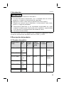
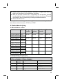
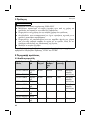
2 Produktbeschreibung
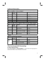
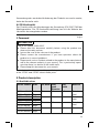
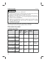
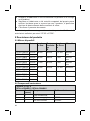
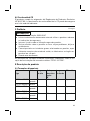
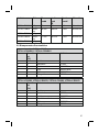
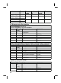
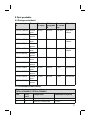
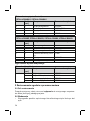
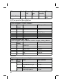
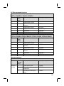
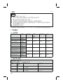
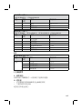
2.1 Verfügbare Größen
Artikelnummer Seite Schie
nenbreite
Gelenk
kopf
Ø
Schlitz
breite
Material
17F31=L26X2.5 links
17F31=R26X2.5 rechts
15mm 26mm 2.5 mm Edelstahl
17F31=L28X3 links
17F31=R28X3 rechts
16mm 28mm 3mm Edelstahl
17F31=L30X3 links
17F31=R30X3 rechts
17mm 30mm 3mm Edelstahl
17F32=L26X2.5 links
17F32=R26X2.5 rechts
15mm 26mm 2.5 mm Aluminium
17F32=L28X3 links
17F32=R28X3 rechts
16mm 28mm 3mm Aluminium
17F32=L30X3 links
17F32=R30X3 rechts
17mm 30mm 3mm Aluminium
4

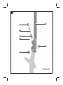
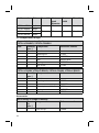
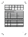
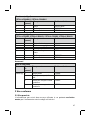
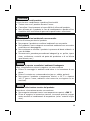
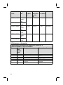
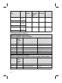
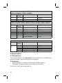
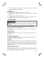
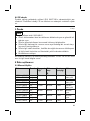
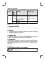
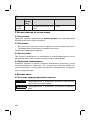
2.2 Bauteile/Konstruktion
Lieferumfang (siehe Abb.1)
17F31=L/R26X2.5, 17F32=L/R26X2.5
Pos. Menge
[Stück]
Bauteil Artikelkennzeichen
1 1 Gelenkschiene
2 1 Splintbolzen 17Y93*
3 1 Gelenkschraube 501S32*
4 1 Kugel 509Y2=3/16"
6 1 Feder 513D18*
7 1 Gewindestift 17Y18*
Lieferumfang (siehe Abb.1)
17F31=L/R28X3, 17F31=L/R30X3, 17F32=L/R28X3, 17F32=L/R30X3
Pos. Menge
[Stück]
Bauteil Artikelkennzeichen
1 1 Gelenkschiene
2 1 Splintbolzen 17Y93*
3 1 Gelenkschraube 501S32*
5 1 Druckstück mit Kugel 17Y80
6 1 Feder 513D18*
7 1 Gewindestift 17Y18*
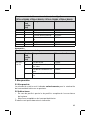
Zubehör
Nicht im Lieferumfang enthalten
Pos. Menge
[Stück]
Bauteil Artikelkennzeichen
1 Fußbügel 17B58*
1 Schuhbügel, doppelseitig 17F33*
1 System-Schuhbügel 17B65*
ohne
Abb.
1 System-Schuhplatte 17F35*
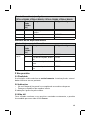
3 Bestimmungsgemäße Verwendung
3.1 Verwendungszweck
Das Orthesengelenk ist ausschließlich zur orthetischen Versorgung der un
teren Extremität bei einem Patienten einzusetzen.
5

3.2 Indikationen
• Bei Teillähmung oder kompletter Lähmung der Beinmuskulatur
• Orthopädische Erkrankungen der unteren Extremität
Die Indikation wird vom Arzt gestellt.
3.3 Lebensdauer
Das Produkt ist bei bestimmungsgemäßer Verwendung und fachgerechter
Montage für eine Lebensdauer von 3Jahren ausgelegt.
3.4 Qualifikation
Die Versorgung eines Patienten mit dem Produkt darf nur von ausgebilde
tem Fachpersonal vorgenommen werden. Es wird vorausgesetzt, dass das
Fachpersonal im Umgang mit den unterschiedlichen Techniken, Materialien,
Werkzeugen und Maschinen vertraut ist.
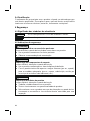
4 Sicherheit
4.1 Bedeutung der Warnsymbolik
VORSICHT Warnung vor möglichen Unfall- und Verletzungsgefahren.
HINWEIS Warnung vor möglichen technischen Schäden.
4.2 Sicherheitshinweise
VORSICHT
Überbeanspruchung durch Gebrauch an mehr als einem Patienten
Verletzungsgefahr und Funktionsverlust sowie Beschädigungen am Pro
dukt
►Verwenden Sie das Produkt nur an einem Patienten.
►Beachten Sie die Wartungsempfehlung.
VORSICHT
Überbeanspruchung tragender Bauteile
Verletzungen durch Funktionsveränderung oder –verlust
►Verwenden Sie das Produkt nur für den definierten Einsatzbereich.
►Falls das Produkt extremen Belastungen ausgesetzt wurde (z.B. durch
Sturz), sorgen Sie für geeignete Maßnahmen (z.B. Reparatur, Aus
tausch, Kontrolle durch den Kundenservice des Herstellers, etc.).
6

VORSICHT
Mechanische Beschädigung des Produkts
Verletzungen durch Funktionsveränderung oder –verlust
►Arbeiten Sie sorgfältig mit dem Produkt.
►Prüfen Sie das Produkt auf Funktion und Gebrauchsfähigkeit.
►Verwenden Sie das Produkt bei Funktionsveränderungen oder -verlust
nicht weiter und lassen Sie es durch autorisiertes Fachpersonal kon
trollieren.
VORSICHT
Verwendung unter unzulässigen Umgebungsbedingungen
Verletzungsgefahr durch Schäden am Produkt
►Setzen Sie das Produkt keinen unzulässigen Umgebungsbedingungen
aus.
►Wenn das Produkt unzulässigen Umgebungsbedingungen ausgesetzt
war, prüfen Sie es auf Schäden.
►Verwenden Sie das Produkt bei offensichtlichen Schäden oder im
Zweifelsfall nicht weiter.
►Sorgen Sie im Bedarfsfall für geeignete Maßnahmen (z.B. Reinigung,
Reparatur, Ersatz, Kontrolle durch den Hersteller oder eine Fachwerk
statt, etc.).
HINWEIS
Produkt wird falschen Umgebungsbedingungen ausgesetzt
Beschädigungen, Versprödung oder Zerstörung durch unsachgemäße
Handhabung
►Vermeiden Sie die Lagerung bei kondensierender Umgebungsfeuch
tigkeit.
►Vermeiden Sie den Kontakt mit abrasiven Medien (z.B. Sand, Staub).
►Setzen Sie das Produkt keinen Temperaturen unter -10°C und über
+60°C aus (z.B. Sauna, übermäßiger Sonneneinstrahlung, Trocknen
auf der Heizung).
HINWEIS
Thermische Überbelastung des Produkts
Beschädigung durch unsachgemäße thermische Bearbeitung
►Führen Sie keine Wärmebehandlung über 300°C durch.
7

►Entfernen Sie vor der thermischen Bearbeitung sämtliche temperatur
kritischen Komponenten (z.B. Kunststoffe).
5 Gebrauchsfähigkeit herstellen
VORSICHT
Fehlerhafter Aufbau oder Montage
Verletzungen durch Funktionsveränderung oder -verlust
►Die Montage darf nur von ausgebildetem Fachpersonal durchgeführt
werden.
►Beachten Sie die Aufbau- und Montagehinweise.
VORSICHT
Wiederholtes Schränken an der gleichen Stelle
Verletzungsgefahr durch Bruch der Schiene, Funktionsveränderung oder
–verlust
►Vermeiden Sie wiederholtes Schränken an der gleichen Stelle.
INFORMATION
Parallele Ausrichtung der Orthesengelenke
Den Justiersatz 743R6 zur Platzierung der Orthesengelenke am Gipspositiv
verwenden.
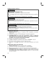
Schienen anrichten
>Benötigte Werkzeuge: Schraubstock, 2 Schränkeisen 711S*, Schleif
maschine, Schraubendreher, Loctite 241
1) Zum Anrichten der Gelenkschiene die Schränkeisen 711S* verwenden.
2) INFORMATION: Für die 17F32 Gelenkschiene aus Aluminium keine
scharfkantigen Schränkeisen benutzen, nur Schränkeisen 711S4
oder Schränkeisen mit abgerundeten Kanten verwenden.
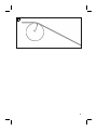
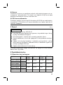
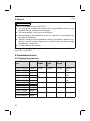
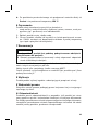
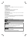
3) Die Schiene anrichten bis das gewünschte Ergebnis erreicht ist.
4) Den Biegeradius von 10mm nicht unterschreiten (siehe Abb.2).
5) Die Riefen und Grate durch Schleifen entfernen.
6) Zur Endmontage die Gelenkschraube mit Loctite 241 sichern.
8

Fußbügel anrichten
>Benötigte Werkzeuge: Schraubstock, Schränkeisen 711S*, Schleifma
schine
1) Zum Anrichten des Fußbügels die Schränkeisen 711S* verwenden.
2) Ein Schränkeisen in einen Schraubstock einspannen und den Fußbügel
positionieren.
3) INFORMATION: Im Einsteckbereich nicht schränken oder ander
weitig bearbeiten, um Bruchgefahr zu vermeiden. Den Fußbügel mit
dem Schränkeisen anpassen.
4) Die Riefen und Grate durch Schleifen entfernen.
Fußbügel montieren
>Voraussetzung: Die Orthesenknöchelgelenke sind demontiert. Dazu
die Gelenkschraube und den Splintbolzen aus dem Gelenk entfernen.
1) Die angerichteten Fußbügel in die Orthesenknöchelgelenke einsetzen.
2) Den Fußbügel und das Orthesengelenk mit dem Splintbolzen und der
Gelenkschraube montieren.
3) Zur Endmontage die Schraubverbindung mit Loctite 241 sichern.
Korrosionsschutz verbessern
Edelstahl
Das Orthesengelenk 17F31 aus Edelstahl ist mit blanker Oberfläche, die an
sich Korrosionsschutz bietet. Schleifen, Polieren und Sintern verbessern
den Korrisionsschutz.
►HINWEIS! Zum Polieren von Edelstahl keine eisenhaltige Polier
paste verwenden. Die mikrofeinen Eisenpartikel genügen, um eine Kor
rosion einzuleiten.
Aluminium
Das Orthesengelenk 17F32 ist aus Aluminium.
►HINWEIS! Führen Sie keine Wärmebehandlung über 200°C durch.
►Schweißen Sie nicht! Stellen Sie eine Schraub- oder Nietverbindung
her.
Ottobock empfiehlt
Zum Schleifen: Eisenoxidfreie Bänder 649G9, Kör
nung 280 – 320
Zum Polieren: Schwabbelscheiben mit Wiener
Kalk bestreichen,
Nicht-eisenhaltige Schleifpaste
649Z4
9

Zum Oberflächenbeschichten: Sinterpulver 618T40
►Nach dem Schleifen die Oberflächen polieren, insbesondere auf die
Kanten achten.
►Zum Oberflächebeschichten das Material nicht länger als 5Minuten
und bei maximal 150°C erwärmen.
6 Reinigung
Reinigen Sie das Produkt umgehend nach Kontakt mit:
• Salzwasser, Chlorwasser, Seifenwasser, Schweiß, Urin, Spritzwasser
(z.B. nach Regen) und Verschmutzungen.
1) Das Produkt mit reinem Süßwasser abspülen.
2) Das Produkt mit einem Tuch abtrocknen oder an der Luft trocknen las
sen. Direkte Hitzeeinwirkung vermeiden (z.B. Ofen- oder Heizkörperhit
ze).
7 Wartung
INFORMATION
Möglicherweise ist das Produkt patientenspezifisch einer erhöhten
Belastung ausgesetzt.
►Verkürzen Sie die Wartungsintervalle gemäß den zu erwartenden Be
lastungen.
Der Hersteller schreibt für das Produkt mindestens eine halbjährliche Funkti
ons- und Verschleißkontrolle vor.
Nur Spezialschmiermittel 633F7 verwenden.
Die Ersatzteile sind im Kapitel Produktbeschreibung unter „Bauteile/Kon
struktion“ aufgeführt.
8 Entsorgung
Das Produkt gemäß den geltenden nationalen Vorschriften entsorgen.
9 Rechtliche Hinweise
Alle rechtlichen Bedingungen unterliegen dem jeweiligen Landesrecht des
Verwenderlandes und können dementsprechend variieren.
9.1 Haftung
Der Hersteller haftet, wenn das Produkt gemäß den Beschreibungen und
Anweisungen in diesem Dokument verwendet wird. Für Schäden, die durch
Nichtbeachtung dieses Dokuments, insbesondere durch unsachgemäße
10

Verwendung oder unerlaubte Veränderung des Produkts verursacht werden,
haftet der Hersteller nicht.
9.2 CE-Konformität
Das Produkt erfüllt die Anforderungen der Verordnung (EU) 2017/745 über
Medizinprodukte. Die CE-Konformitätserklärung kann auf der Website des
Herstellers heruntergeladen werden.
1 Foreword English
INFORMATION
Date of last update: 2021-05-07
►Please read this document carefully before using the product and
observe the safety notices.
►Instruct the user in the safe use of the product.
►Please contact the manufacturer if you have questions about the
product or in case of problems.
►Report each serious incident related to the product to the manufacturer
and to the relevant authority in your country. This is particularly import
ant when there is a decline in the health state.
►Please keep this document for your records.
These instructions for use provide you with important information on the use
of the 17F31* and 17F32* orthotic ankle joints.
2 Product description
2.1 Available sizes
Article number Side Bar width Joint
head
Diameter
Slot
width
Material
17F31=L26X2.5 Left
17F31=R26X2.5 Right
15mm 26mm 2.5mm Stainless
steel
17F31=L28X3 Left
17F31=R28X3 Right
16mm 28mm 3mm Stainless
steel
17F31=L30X3 Left
17F31=R30X3 Right
17mm 30mm 3mm Stainless
steel
17F32=L26X2.5 Left
17F32=R26X2.5 Right
15mm 26mm 2.5mm Aluminium
11

Article number Side Bar width Joint
head
Diameter
Slot
width
Material
17F32=L28X3 Left
17F32=R28X3 Right
16mm 28mm 3mm Aluminium
17F32=L30X3 Left
17F32=R30X3 Right
17mm 30mm 3mm Aluminium
2.2 Components/design
Scope of delivery (see fig.1)
17F31=L/R26X2.5, 17F32=L/R26X2.5
Item Quantity
[pcs.]
Component Reference number
1 1 Joint bar
2 1 Bearing nut 17Y93*
3 1 Joint screw 501S32*
4 1 Ball 509Y2=3/16"
6 1 Spring 513D18*
7 1 Set screw 17Y18*
Scope of delivery (see fig.1)
17F31=L/R28X3, 17F31=L/R30X3, 17F32=L/R28X3, 17F32=L/R30X3
Item Quantity
[pcs.]
Component Reference number
1 1 Joint bar
2 1 Bearing nut 17Y93*
3 1 Joint screw 501S32*
5 1 Thrust piece with ball 17Y80
6 1 Spring 513D18*
7 1 Set screw 17Y18*
Accessories
Not included in scope of delivery
Item Quant
ity
[pcs.]
Component Reference number
1 Foot stirrup 17B58*
12

Not included in scope of delivery
Item Quant
ity
[pcs.]
Component Reference number
1 Shoe stirrup, double-
sided
17F33*
1 System shoe stirrup 17B65*
not illus
trated
1 System shoe plate 17F35*
3 Intended use
3.1 Indications for use
The orthosis joint is intended exclusively for orthotic fittings of the lower
limbs on one patient.
3.2 Indications
• Partial or total paralysis of the leg muscles
• Orthopaedic diseases of the lower limbs
Indications must be determined by the physician.
3.3 Lifetime
The product is designed for a lifetime of 3years when used as intended and
assembled professionally.
3.4 Qualification
Patients may be fitted with the product only by trained qualified personnel.
The qualified personnel must be familiar with the handling of the various
techniques, materials, machines and tools.
4 Safety
4.1 Explanation of warning symbols
CAUTION Warning regarding possible risks of accident or injury.
NOTICE Warning regarding possible technical damage.
4.2 Safety instructions
CAUTION
Excessive strain due to use on more than one patient
Risk of injury and loss of functionality as well as damage to the product
13

►Use the product on only one patient.
►Observe the maintenance recommendations.
CAUTION
Excessive strain on load-bearing components
Injuries due to changes in or loss of functionality
►Only use the product for the defined area of application.
►If the product has been exposed to extreme strain (e.g.due to falling),
take any necessary measures (e.g.repair, replacement, inspection by
the manufacturer's customer service, etc.).
CAUTION
Mechanical damage to the product
Injuries due to changes in or loss of functionality
►Use caution when working with the product.
►Check the product for proper function and readiness for use.
►In case of changes in or loss of functionality, discontinue use of the
product and have it checked by authorised, qualified personnel.
CAUTION
Use under restricted environmental conditions
Risk of injury due to damage to the product
►Do not expose the product to restricted environmental conditions.
►If the product has been exposed to restricted environmental conditions,
check it for damage.
►If damage is apparent or in case of doubt, do not continue using the
product.
►Take suitable measures if required (e.g.cleaning, repair, replacement,
inspection by the manufacturer or a specialist workshop etc.).
NOTICE
Exposure of the product to unsuitable environmental conditions
Damage, brittleness or destruction due to improper handling
►Avoid storage in condensing ambient humidity.
►Avoid contact with abrasive substances (e.g.sand, dust).
►Do not expose the product to temperatures below -10°C (14°F) or
above +60°C (140°F) (e.g.sauna, excessive sunlight, drying on a
radiator).
14

NOTICE
Thermal overloading of the product
Damage due to improper thermal treatment
►Do not carry out any heat treatment at temperatures above 300°C
(570°F).
►Prior to thermal treatment, remove all temperature-critical components
(suchas plastic parts).
5 Preparing the product for use
CAUTION
Incorrect alignment or assembly
Injuries due to changes in or loss of functionality
►The product may only be installed by trained, qualified personnel.
►Observe the alignment and assembly instructions.
CAUTION
Repeated bending at the same position
Risk of injury due to breakage of the bar, change in or loss of functionality
►Avoid repeated bending at the same position.
INFORMATION
Parallel alignment of the orthotic joints
Use the 743R6 alignment fixture to position the orthotic joints on the plaster
positive.
Shaping the bars
>Required tools: Vice, 2x 711S* bending irons, grinding machine,
screwdriver, Loctite241
1) Use the 711S* bending irons for contouring the joint bar.
2) INFORMATION: Do not use bending irons with sharp edges for the
17F32 aluminium joint bar; use only the 711S4 bending irons or
bending irons with rounded edges.
3) Contour the bar until the desired result is obtained.
4) Observe the minimum bending radius of 10mm (see fig.2).
5) Remove grooves and burrs by grinding.
6) For final assembly, secure the joint screw with Loctite241.
15

Bending the foot stirrups
>Required tools: Vice, 711S* bending iron, grinding machine
1) Use the 711S* bending irons for contouring the foot stirrup.
2) Clamp a bending iron in a vice and position the foot stirrup.
3) INFORMATION: To prevent the risk of breakage, do not bend or
otherwise modify the insertion zone. Adapt the foot stirrup with the
bending iron.
4) Remove grooves and burrs by grinding.
Mounting the foot stirrup
>Prerequisite: The orthotic ankle joints are disassembled. To do so,
remove the joint screw and the bearing nut from the joint.
1) Insert the contoured foot stirrup into the orthotic ankle joint.
2) Assemble the foot stirrup and the orthotic joint with the bearing nut and
the joint screw.
3) For final assembly, secure the screw connection with Loctite241.
Improving corrosion protection
Stainless steel
The 17F31 orthotic joint made of stainless steel has a shiny surface that is
protected against corrosion. Sanding, polishing and sintering improves the
protection against corrosion.
►NOTICE! Do not use polishing pastes containing iron to polish
stainless steel. The micro-fine iron particles are sufficient to initiate cor
rosion.
Aluminium
The 17F32 orthotic joint is made of aluminium.
►NOTICE! Do not carry out any heat treatment at temperatures
above 200°C.
►Do not weld! Use a screw or rivet connection.
Ottobock recommends
For sanding: 649G9 belts, free of iron oxide, 280
– 320 grit
For polishing: Polishing mop coated with Vienna
chalk
649Z4 polishing paste, non-ferrous
For surface coating: 618T40 Sintering powder
►After sanding, polish the surfaces, paying special attention to the edges.
16

►Do not heat the material longer than 5minutes at max. 150°C for sur
face coating.
6 Cleaning
Promptly clean the product after contact with:
• Water containing salt, chlorine or soap, perspiration, urine or splashed
water (e.g.after rain) and soiling.
1) Rinse the product with clear fresh water.
2) Dry the product with a cloth or allow it to air dry. Avoid exposure to direct
heat (e.g.from an oven or radiator).
7 Maintenance
INFORMATION
The product may be exposed to increased loads by the patient.
►Shorten the maintenance intervals according to the expected loads.
The manufacturer requires at least a semi-annual inspection of the product
to verify functionality and check for wear.
Only use 633F7 special lubricant.
Spare parts are listed in the section "Components/design".
8 Disposal
Dispose of the product in accordance with national regulations.
9 Legal information
All legal conditions are subject to the respective national laws of the country
of use and may vary accordingly.
9.1 Liability
The manufacturer will only assume liability if the product is used in accord
ance with the descriptions and instructions provided in this document. The
manufacturer will not assume liability for damage caused by disregarding the
information in this document, particularly due to improper use or unauthor
ised modification of the product.
9.2 CE conformity
The product meets the requirements of Regulation (EU) 2017/745 on medic
al devices. The CE declaration of conformity can be downloaded from the
manufacturer's website.
17

1 Avant-propos Français
INFORMATION
Date de la dernière mise à jour: 2021-05-07
►Veuillez lire attentivement l’intégralité de ce document avant d’utiliser le
produit ainsi que respecter les consignes de sécurité.
►Apprenez à l’utilisateur comment utiliser son produit en toute sécurité.
►Adressez-vous au fabricant si vous avez des questions concernant le
produit ou en cas de problèmes.
►Signalez tout incident grave survenu en rapport avec le produit, notam
ment une aggravation de l’état de santé, au fabricant et à l’autorité
compétente de votre pays.
►Conservez ce document.
La notice d’utilisation fournit des informations importantes sur l’utilisation
des articulations de cheville pour orthèse 17F31* et 17F32*.
2 Description du produit
2.1 Tailles disponibles
Référence Côté Largeur
de fer
rure
Tête
d’articul
ation
Ø
Largeur
de fente
Matériau
17F31=L26X2.5 Gauch
e
17F31=R26X2.5 Droit
15mm 26mm 2,5 mm Acier in
oxydable
17F31=L28X3 Gauch
e
17F31=R28X3 Droit
16mm 28mm 3mm Acier in
oxydable
17F31=L30X3 Gauch
e
17F31=R30X3 Droit
17mm 30mm 3mm Acier in
oxydable
17F32=L26X2.5 Gauch
e
17F32=R26X2.5 Droit
15mm 26mm 2,5 mm Aluminium
17F32=L28X3 Gauch
e
17F32=R28X3 Droit
16mm 28mm 3mm Aluminium
18

Référence Côté Largeur
de fer
rure
Tête
d’articul
ation
Ø
Largeur
de fente
Matériau
17F32=L30X3 Gauch
e
17F32=R30X3 Droit
17mm 30mm 3mm Aluminium
2.2 Construction / éléments constitutifs
Contenu de la livraison (voir ill.1)
17F31=L/R26X2.5, 17F32=L/R26X2.5
Pos. Quantité
[unité]
Composant Référence
1 1 Ferrure articulée
2 1 Écrou relieur 17Y93*
3 1 Vis d’articulation 501S32*
4 1 Bille 509Y2=3/16"
6 1 Ressort 513D18*
7 1 Vis sans tête 17Y18*
Contenu de la livraison (voir ill.1)
17F31=L/R28X3, 17F31=L/R30X3, 17F32=L/R28X3, 17F32=L/R30X3
Pos. Quantité
[unité]
Composant Référence
1 1 Ferrure articulée
2 1 Écrou relieur 17Y93*
3 1 Vis d’articulation 501S32*
5 1 Pièce de pression avec
bille
17Y80
6 1 Ressort 513D18*
7 1 Vis sans tête 17Y18*
19

Accessoires
Composants non compris dans la livraison
Pos. Quanti
té
[unité]
Composant Référence
1 Étrier de pied 17B58*
1 Étrier de chaussure, bila
téral
17F33*
1 Système d’étrier de
chaussure
17B65*
Sans ill.
1 Système de plaque pour
chaussure
17F35*
3 Utilisation conforme
3.1 Usage prévu
L’articulation d’orthèse est exclusivement destinée à l’appareillage orthé
tique des membres inférieurs d’un patient.
3.2 Indications
• Paralysie partielle ou complète des muscles de la jambe
• Maladies orthopédiques du membre inférieur
L’indication est déterminée par le médecin.
3.3 Durée de vie
Le produit est conçu pour une durée de vie de 3ans si son utilisation est
conforme et le montage correct.
3.4 Qualification
Seul un personnel spécialisé dûment formé est autorisé à appareiller un pa
tient avec le produit. Il est entendu que ces professionnels sont familiarisés
à l’utilisation des diverses méthodes et différents matériaux, outils et ma
chines requis.
4 Sécurité
4.1 Signification des symboles de mise en garde
PRUDENCE Mise en garde contre les éventuels risques d’accidents
et de blessures.
20
A página está carregando...
A página está carregando...
A página está carregando...
A página está carregando...
A página está carregando...
A página está carregando...
A página está carregando...
A página está carregando...
A página está carregando...
A página está carregando...
A página está carregando...
A página está carregando...
A página está carregando...
A página está carregando...
A página está carregando...
A página está carregando...
A página está carregando...
A página está carregando...
A página está carregando...
A página está carregando...
A página está carregando...
A página está carregando...
A página está carregando...
A página está carregando...
A página está carregando...
A página está carregando...
A página está carregando...
A página está carregando...
A página está carregando...
A página está carregando...
A página está carregando...
A página está carregando...
A página está carregando...
A página está carregando...
A página está carregando...
A página está carregando...
A página está carregando...
A página está carregando...
A página está carregando...
A página está carregando...
A página está carregando...
A página está carregando...
A página está carregando...
A página está carregando...
A página está carregando...
A página está carregando...
A página está carregando...
A página está carregando...
A página está carregando...
A página está carregando...
A página está carregando...
A página está carregando...
A página está carregando...
A página está carregando...
A página está carregando...
A página está carregando...
A página está carregando...
A página está carregando...
A página está carregando...
A página está carregando...
A página está carregando...
A página está carregando...
A página está carregando...
A página está carregando...
A página está carregando...
A página está carregando...
A página está carregando...
A página está carregando...
A página está carregando...
A página está carregando...
A página está carregando...
A página está carregando...
A página está carregando...
A página está carregando...
A página está carregando...
A página está carregando...
A página está carregando...
A página está carregando...
A página está carregando...
A página está carregando...
A página está carregando...
A página está carregando...
A página está carregando...
A página está carregando...
A página está carregando...
A página está carregando...
A página está carregando...
A página está carregando...
A página está carregando...
A página está carregando...
A página está carregando...
A página está carregando...
A página está carregando...
A página está carregando...
A página está carregando...
A página está carregando...
A página está carregando...
A página está carregando...
A página está carregando...
A página está carregando...
A página está carregando...
A página está carregando...
A página está carregando...
A página está carregando...
-
 1
1
-
 2
2
-
 3
3
-
 4
4
-
 5
5
-
 6
6
-
 7
7
-
 8
8
-
 9
9
-
 10
10
-
 11
11
-
 12
12
-
 13
13
-
 14
14
-
 15
15
-
 16
16
-
 17
17
-
 18
18
-
 19
19
-
 20
20
-
 21
21
-
 22
22
-
 23
23
-
 24
24
-
 25
25
-
 26
26
-
 27
27
-
 28
28
-
 29
29
-
 30
30
-
 31
31
-
 32
32
-
 33
33
-
 34
34
-
 35
35
-
 36
36
-
 37
37
-
 38
38
-
 39
39
-
 40
40
-
 41
41
-
 42
42
-
 43
43
-
 44
44
-
 45
45
-
 46
46
-
 47
47
-
 48
48
-
 49
49
-
 50
50
-
 51
51
-
 52
52
-
 53
53
-
 54
54
-
 55
55
-
 56
56
-
 57
57
-
 58
58
-
 59
59
-
 60
60
-
 61
61
-
 62
62
-
 63
63
-
 64
64
-
 65
65
-
 66
66
-
 67
67
-
 68
68
-
 69
69
-
 70
70
-
 71
71
-
 72
72
-
 73
73
-
 74
74
-
 75
75
-
 76
76
-
 77
77
-
 78
78
-
 79
79
-
 80
80
-
 81
81
-
 82
82
-
 83
83
-
 84
84
-
 85
85
-
 86
86
-
 87
87
-
 88
88
-
 89
89
-
 90
90
-
 91
91
-
 92
92
-
 93
93
-
 94
94
-
 95
95
-
 96
96
-
 97
97
-
 98
98
-
 99
99
-
 100
100
-
 101
101
-
 102
102
-
 103
103
-
 104
104
-
 105
105
-
 106
106
-
 107
107
-
 108
108
-
 109
109
-
 110
110
-
 111
111
-
 112
112
-
 113
113
-
 114
114
-
 115
115
-
 116
116
-
 117
117
-
 118
118
-
 119
119
-
 120
120
-
 121
121
-
 122
122
-
 123
123
-
 124
124


em outras línguas
- français: Ottobock 17f31 Mode d'emploi
- dansk: Ottobock 17f31 Betjeningsvejledning
- Türkçe: Ottobock 17f31 Kullanma talimatları