
Seccionadoras tipo fusível
Fuse switch disconnectors
Seccionadores tipo fusible
Motors | Automation | Energy | Transmission & Distribution | Coatings
Manual for fuse switch disconnectors
Manual de instruções de seccionadoras tipo fusível
Manual de instrucciones de seccionadores tipo fusible
FSW 160

www.weg.net
Manual de instruções para a montagem e manutenção de seccionadoras tipo fusível2
17-23
Manual de instrucciones para el montaje y
mantenimiento de seccionadores tipo fusible
Español
3-9
Manual de instruções para a montagem e
manutenção de seccionadoras tipo fusível
Português
10-16
English
Instruction manual for mounting and
service of fuse switch disconnectors

www.weg.net
Manual de instruções para a montagem e manutenção de seccionadoras tipo fusível
3
CONTEÚDO
PORTUGUÊS
ÍNDICE
1. OPERAÇÕES BÁSICAS .............................................................................. 4
1.1. ABERTURA DA TAMPA ...................................................................... 4
1.2. FECHAMENTO DA PROTEÇÃO ........................................................ 4
1.3. RETIRADA DA PROTEÇÃO ................................................................ 4
1.4. MONTAGEM DA TAMPA .................................................................... 4
1.5. RETIRADA DA COBERTURA PARA TERMINAIS ............................ 4
1.6. MONTAGEM DA PROTEÇÃO DE TERMINAIS ................................. 5
2. MONTAGEM DA SECCIONADORA ........................................................... 5
2.1. MONTAGEM DA SECCIONADORA NA BASE DE MONTAGEM ..... 5
3. FIXAÇÃO DOS CONDUTORES DE SAÍDA ............................................... 6
3.1. FIXAÇÃO DOS CONDUTORES COM TERMINAL DE CABO
GRAMPO - PARAFUSO TIPO M ......................................................... 6
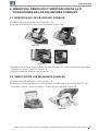
4. INSERÇÃO, RETIRADA E VERIFICAÇÃO DAS CONDIÇÕES DOS
ELOS-FUSÍVEIS .......................................................................................... 7
4.1. INSERÇÃO DOS ELOS-FUSÍVEIS ..................................................... 7
4.2. RETIRADA DOS ELOS-FUSÍVEIS ..................................................... 7
4.3. VERIFICAÇÃO DAS CONDIÇÕES DOS ELOS-FUSÍVEIS ............... 8
5. VEDAÇÃO DA SECCIONADORA ............................................................... 8
5.1. LACRE COM FIO LACRE ................................................................... 8
5.2. TRAVAMENTO E DESTRAVAMENTO DOS PONTOS DE
MEDIÇÃO ............................................................................................ 9
5.3. CONTATOS AUXILIARES ................................................................... 9
6. DESCARTE DO MATERIAL UTILIZADO ................................................... 9
7. CONDIÇÕES DE TRANSPORTE E ARMAZENAMENTO ......................... 9

www.weg.net
Manual de instruções para a montagem e manutenção de seccionadoras tipo fusível4
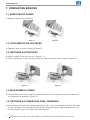
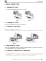
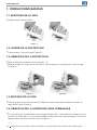
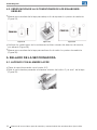
1. OPERAÇÕES BÁSICAS
1.1. ABERTURA DA TAMPA
Segure a alça e abra a tampa.
1.2. FECHAMENTO DA PROTEÇÃO
Segure a alça e feche a tampa (Figura 2).
1.3. RETIRADA DA PROTEÇÃO
Abra a tampa (de acordo com o capítulo 1.1);
Mova a tampa ao longo da base da seccionadora e então retire a tampa (Figura 3).
1.4. MONTAGEM DA TAMPA
Insira a tampa na base da seccionadora e então mova a tampa ao longo da base da
seccionadora firmemente (Figura 4).
1.5. RETIRADA DA COBERTURA PARA TERMINAIS
Na proteção de terminais selecionada (Figura 5) 1, com uma chave de fenda desloque
um dos grampos da proteção (Figura 6) 2 e então desloque o segundo grampo e ao
mesmo tempo retire a proteção da base (Figura 7).
Figura 1 Figura 2
Figura 3
Figura 4

www.weg.net
Manual de instruções para a montagem e manutenção de seccionadoras tipo fusível
5
2
1
2
1
2
1
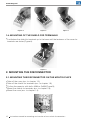
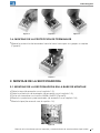
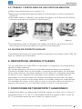
1.6. MONTAGEM DA PROTEÇÃO DE TERMINAIS
g
Mova a proteção de terminais até a base até que seu grampos se prendam (Figura 8).
Figura 5
Figura 7
Figura 6
Figura 8
2. MONTAGEM DA SECCIONADORA
2.1. MONTAGEM DA SECCIONADORA NA BASE DE MONTAGEM
Retire a tampa (de acordo com o capítulo 1.3);
Retire a proteção de terminais (de acordo com o capítulo 1.5);
Fixe a seccionadora com parafusos 4xM6 ou 2xM6 (Figura 9) até que se tenha uma
boa fixação no painel;
Montar os protetores para terminais (de acordo com o capítulo 1.6).
Monte a tampa (de acordo com o capítulo 1.4).
Figura 9

www.weg.net
Manual de instruções para a montagem e manutenção de seccionadoras tipo fusível6
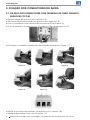
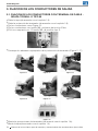
3. FIXAÇÃO DOS CONDUTORES DE SAÍDA
3.1. FIXAÇÃO DOS CONDUTORES COM TERMINAL DE CABO GRAMPO -
PARAFUSO TIPO M
Retire a tampa (de acordo com o capítulo 1.3);
Retire a proteção de terminais (de acordo com o capítulo 1.5);
Fixe os condutores com parafuso M5 e torque de 3 Nm (Figura 10);
O kit de parafusos é composto por 12 parafusos M5 e 6 grampos tipo S;
Destaque os elementos apropriados da proteção de terminais (Figura 11-17);
Monte as proteções de terminais (de acordo com o capítulo 1.6);
Monte a tampa (de acordo com o capítulo 1.4).
Figura 10
Figura 17
Figura 11
Figura 14
Figura 12
Figura 15
Figura 13
Figura 16

www.weg.net
Manual de instruções para a montagem e manutenção de seccionadoras tipo fusível
7
4. INSERÇÃO, RETIRADA E VERIFICAÇÃO DAS CONDIÇÕES
DOS ELOS-FUSÍVEIS
4.1. INSERÇÃO DOS ELOS-FUSÍVEIS
Retire a tampa (de acordo com o capítulo 1.3);
Coloque o elo-fusível em um porta-fusível (Figura 18);
g
Mova um elo-fusível ao longo da tampa (Figura 19) até a trava de elos-fusíveis prender
(Figura 20, Figura 21);
g
Monte a tampa (de acordo com o capítulo 1.4).
Figura 18 Figura 19
Figura 20 Figura 21
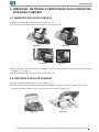
4.2. RETIRADA DOS ELOS-FUSÍVEIS
g
Retire a tampa (de acordo com o capítulo 1.3);
g
Pressione o botão de liberação para travamento de elos-fusíveis (Figura 22) e, em
seguida, afaste e retire o elo-fusível do porta-fusível (Figura 23).
Figura 22
Figura 23

www.weg.net
Manual de instruções para a montagem e manutenção de seccionadoras tipo fusível8
4.3. VERIFICAÇÃO DAS CONDIÇÕES DOS ELOS-FUSÍVEIS
Mova um corrediça da tampa para baixo a fim de expor os pontos de medição (Figura 24);
Figura 27
Figura 24 Figura 25 Figura 26
Verifique as condições dos elos-fusíveis através do detector de tensão, por exemplo (Figura 25);
Mova uma corrediça da tampa para cima a fim de cobrir os pontos de medição (Figura 26).
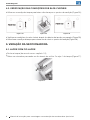
5. VEDAÇÃO DA SECCIONADORA
5.1. LACRE COM FIO LACRE
g
Feche a tampa (de acordo com o capítulo 1.2);
g
Sele a seccionadora passando um fio através do orifício 2 e alça 1 da tampa (Figura 27).
1
2

www.weg.net
Manual de instruções para a montagem e manutenção de seccionadoras tipo fusível
9
5.2. TRAVAMENTO E DESTRAVAMENTO DOS PONTOS DE MEDIÇÃO
g
Retire a tampa (de acordo com o capítulo 1.3);
g
Mova uma corrediça da tampa para baixo a fim de expor os pontos de medição
(Figura 26);
g
Para travar, mova os elementos de travamento de acordo com a direção da seta
(Figura 28) até encaixarem na guia da tampa (Figura 30);
g
Para destravar, mova os elementos de travamento de acordo com a direção da seta
(Figura 29) até pularem na guia da tampa (Figura 30).
Figura 28
Figura 29 Figura 30
5.3. CONTATOS AUXILIARES
A montagem da chave de contato auxiliar na seccionadora tipo fusível FSW 160 deve ser
realizada pelo fabricante. Não é recomendada a montagem pelo usuário.
6. DESCARTE DO MATERIAL UTILIZADO
As seccionadoras tipo fusível FSW são fabricadas com materiais e tecnologia que não
agridem o meio ambiente.
Normas referentes à proteção do meio ambiente devem ser respeitadas.
O produto utilizado deve ser desmontado e as peças de metal devem ser separadas
das peças plásticas. Peças metálicas sem uso devem ser segregadas em metais não
ferrosos e outros e devem ser sucateadas. Peças plásticas que podem ser recicladas
devem ser enviadas para empresa de reciclagem. Peças plásticas que não podem ser
recicladas devem ser enviadas para empresa especializadas. Embalagens de papelão e
sacos plásticos que são reciclados devem ser enviados para empresas de reciclagem.
Em caso de dúvidas, entre em contato com o fabricante.
7. CONDIÇÕES DE TRANSPORTE E ARMAZENAMENTO
O armazenamento deve ser realizado na embalagem original, em locais secos e limpos
em temperatura superior a -5 ºC e umidade relativa não superior a 80% a temperatura
de +35 ºC.
A temperatura mais alta de 40 ºC, a umidade relativa do ar não deve ser superior a 50%.

www.weg.net
Instruction manual for mounting and service of fuse switch disconnectors10
CONTENT
ENGLISH
1. BASIC OPERATIONS .................................................................................11
1.1. OPENING THE COVER ......................................................................11
1.2. CLOSING THE COVER ......................................................................11
1.3. TAKING OFF THE COVER ................................................................. 11
1.4. MOUNTING THE COVER ..................................................................11
1.5. TAKING OFF THE SHIELD FOR TERMINALS .................................11
1.6. MOUNTING OF THE SHIELD FOR TERMINALS ............................ 12
2. MOUNTING THE DISCONNECTOR ........................................................ 12
2.1. MOUNTING THE DISCONNECTOR ON THE MOUTIG PLATE ..... 12
3. FIXING OUTGOING CONDUCTORS ....................................................... 13
3.1. FIXING CONDUCTORS WITH CABLE TERMINAL -
M TYPE BOLT CLAMP ..................................................................... 13
4. INSERTING, TAKING OUT AND CHECKING THE
CONDITIONS OF THE FUSE LINKS .........................................................14
4.1. INSERTING OF THE FUSE LINKS ....................................................14
4.2. TAKING OUT THE FUSE LINKS ...................................................... 15
4.3. CHECKING THE CONDITIONS OF THE FUSE LINKS................... 15
5. SEALING OF THE DISCONNECTOR ...................................................... 15
5.1. SEALING BY USE OF THE STRING ................................................ 15
5.2. LOCKING AND UNLOCKING OF MEASURING POINTS .............. 16
5.3. AUXILIARY CONTACT BLOCK ........................................................ 16
6. PROCEEDING WITH THE MATERIAL UTILIZED ................................... 16
7. TRANSPORT AND STORAGE CONDITIONS ......................................... 16

www.weg.net
Instruction manual for mounting and service of fuse switch disconnectors
11
1. BASIC OPERATIONS
1.1. OPENING THE COVER
A take the handle and open the cover (Figure 1).
1.2. CLOSING THE COVER
g
A take the handle and close the cover (Figure 2).
1.3. TAKING OFF THE COVER
g
Open the cover (acc. to chapter 1.1);
g
Move the cover along the base of the disconnector and then take off the cover Figure 3.
1.4. MOUNTING THE COVER
g
Insert the cover into the base of disconnector and then move the cover along the base
of disconnector up to firm resistance (Figure 4).
1.5. TAKING OFF THE SHIELD FOR TERMINALS
g
Catch selected shield for terminals and deflect by a screwdriver one of the fasteners of the
shield (Figure 5) 1 and then deflect the second fastener of the cover (Figure 6) 2 and at the
same time withdraw selected shield for terminals from the base (Figure 7).
Figure 1
Figure 2
Figure 3
Figure 4

www.weg.net
Instruction manual for mounting and service of fuse switch disconnectors12
1.6. MOUNTING OF THE SHIELD FOR TERMINALS
g
A withdraw the shield for terminals up to the base until the fasteners of the cover for
terminals are fasten (Figure 8).
2
1
2
1
2
1
Figure 5
Figure 7
Figure 6
Figure 8
2. MOUNTING THE DISCONNECTOR
2.1. MOUNTING THE DISCONNECTOR ON THE MOUTIG PLATE
g
Take off the cover (acc. to chapter 1.3);
g
Take off the shields for terminals (acc. to chapter 1.5);
g
Fix the disconnector with bolts 4xM6 or 2xM6 (Figure 9);
g
Mount the shields for terminals (acc. to chapter 1.6);
g
Mount the cover (acc. to chapter 1.4).
Figure 9

www.weg.net
Instruction manual for mounting and service of fuse switch disconnectors
13
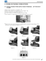
3. FIXING OUTGOING CONDUCTORS
3.1. FIXING CONDUCTORS WITH CABLE TERMINAL - M TYPE BOLT
CLAMP
g
Take off the cover (acc. to chapter 1.3);
g
Take off the shields for terminals (acc. to chapter 1.5);
g
Fix the conductors according Figure 10;
g
Fix the conductor with M5 screw and torque 3 Nm;
g
The screw kit is compound by 12 M5 screw and 6 clips type S;
g
Break down appropriate elements of the shield for terminals depending on the
thickness of a conductor (Figures 11-17);
Figure 10
Figure 17
Figure 11
Figure 14
Figure 12
Figure 15
Figure 13
Figure 16

www.weg.net
Instruction manual for mounting and service of fuse switch disconnectors14
g
Mount the shield for terminals (acc. to chapter 1.6);
g
Mount the cover (acc.to chapter 1.4).
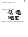
4. INSERTING, TAKING OUT AND CHECKING THE
CONDITIONS OF THE FUSE LINKS
4.1. INSERTING OF THE FUSE LINKS
g
Take off the cover (acc. to chapter 1.3);
g
Place the fuse link in a fuse holder (Figure 18);
g
Move a fuse link along the cover (Figure 19) until the locking for fuse links is fasten
(Figure 20, Figure 21);
g
Mount the cover (acc. to chapter 1.4).
Figure 18 Figure 19
Figure 20 Figure 21

www.weg.net
Instruction manual for mounting and service of fuse switch disconnectors
15
4.2. TAKING OUT THE FUSE LINKS
g
Take off the cover (acc. to chapter 1.3);
g
Press the release button for locking of fuse links (Figure 22), then withdraw and take
out the fuse link from the fuse holder (Figure 23).
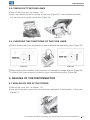
4.3. CHECKING THE CONDITIONS OF THE FUSE LINKS
g
Move a slider of the cover downwards in order to expose the measuring points (Figure 24);
Figure 24 Figure 25 Figure 26
g
Make checking the conditions of the fuse links for example by voltage detector (Figure 25);
g
A slider of the cover upwards in order to cover the measuring points (Figure 26).
5. SEALING OF THE DISCONNECTOR
5.1. SEALING BY USE OF THE STRING
g
Take off the cover (acc. to chapter 1.2);
g
Seal the disconnector passing a string through sealing eye 2 and handle 1 of the cover
(Figure 27).
Figure 22 Figure 23
Figure 27
1
2

www.weg.net
Instruction manual for mounting and service of fuse switch disconnectors16
Figure 28 Figure 29 Figure 30
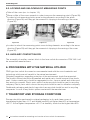
5.2. LOCKING AND UNLOCKING OF MEASURING POINTS
g
Take off the cover (acc. to chapter 1.3);
g
Move a slider of the cover upwards in order to expose the measuring points (Figure 26);
g
In order to lock measuring points move locking elements according to the arrow
direction (Figure 28) until they get the moment of skipping in the moving of the cover
(Figure 30);
g
In order to unlock the measuring points move locking elements according to the arrow
direction (Figure 29) until they get the moment of skipping in the moving of the cover
(Figure 30).
5.3. AUXILIARY CONTACT BLOCK
The assembly of auxiliary contact block in the fuse switch-disconnectors FSW 160 it will
be assembled manufacturers.
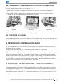
6. PROCEEDING WITH THE MATERIAL UTILIZED
FSW type fuse switch disconnectors are manufactured with the use of materials and
technology which are not harmful to the natural environment.
Obligatory regulations regarding protection of the environment should be respected.
The product utilized should be dismantled and metal parts should be apart from plastic
ones. Useless metal parts should be segregated to non - ferrous metals and others and
they are to be scraped. Plastic parts which can be recycled should be sent to recycling
company. Plastic parts which can not be recycled should be sent to utilization company.
Cardboard packaging and plastic bags which are recycled should be sent to recycling
companies. In case of any doubts please contactwith the manufacturer.
7. TRANSPORT AND STORAGE CONDITIONS
Storage should be performed in original packaging, in dry and clean rooms at
temperaturę higher than -5 °C and related humidity not higher than 80% at temperature
+35 °C. At the highest temperature +40 °C air humidity should not be higher than 50%.

www.weg.net
Manual de instrucciones para el montaje y mantenimiento de seccionadoras tipo fusible
17
CONTENIDO
ESPAÑOL
1. OPERACIONES BASICAS ........................................................................ 18
1.1. APERTURA DE LA TAPA .................................................................. 18
1.2. CIERRE DE LA PROTECCION ........................................................ 18
1.3. REMOCION DE LA PROTECCION .................................................. 18
1.4. MONTAJE DE LA TAPA .................................................................... 18
1.5. REMOCION DE LA COBERTURA PARA TERMINALES ............... 18
1.6. MONTAJE DE LA PROTECCION DE TERMINALES ...................... 19
2. MONTAJE DE LA SECCIONADORA ....................................................... 19
2.1. MONTAJE DE LA SECCIONADORA EN LA BASE DE MONTAJE ... 19
3. FIJACION DE LOS CONDUCTORES DE SALIDA .................................. 20
3.1. FIJACION DE LOS CONDUCTORES CON TERMINAL
DE CABLE - GRAPA TORNILL O TIPO M ....................................... 20
4. INSERCION, REMOCION Y VERIFICACION DE LAS
CONDICIONES DE LOS ESLABONES-FUSIBLES ................................ 21
4.1. INSERCION DE LOS ESLABONES-FUSIBLES .............................. 21
4.2. REMOCION DE LOS ESLABONES-FUSIBLES .............................. 21
4.3. VERIFICACION DE LA S CONDICIONES DE LOS
ESLABONES-FUSIBLES .................................................................. 22
5. SELLADO DE LA SECCIONADORA ....................................................... 22
5.1. LACRADO CON ALAMBRE LACRE ................................................ 22
5.2. TRABADO Y DESTRA BADO DE LOS PUNTOS DE MEDICION .. 23
5.3. BLOQUE DE CONTACTO AUXILIAR ............................................... 23
6. DESCARTE DEL MATERIAL UTILIZADO ............................................... 23
7. CONDICIONES DE TRANSPORTE Y ALMACENADO ........................... 23

www.weg.net
Manual de instrucciones para el montaje y mantenimiento de seccionadoras tipo fusible18
1. OPERACIONES BASICAS
1.1. APERTURA DE LA TAPA
g
Sujete el asa y abra la tapa.
1.2. CIERRE DE LA PROTECCION
g
Lleve a cabo y cierre la tapa (Figura 2).
1.3. REMOCION DE LA PROTECCION
g
Abra la tapa (de acuerdo con el capítulo 1.1);
g
Mueva la tapa a lo largo de la base de la seccionadora, a continuación retire la tapa
(Figura 3).
1.4. MONTAJE DE LA TAPA
g
Inserte la tapa en la base de la seccionadora, luego mueva firmemente la tapa a lo
largo de la base (Figura 4).
1.5. REMOCION DE LA COBERTURA PARA TERMINALES
g
En la protección de terminales seleccionada (Figura 5) 1, retire una de las grapas de la
protección (Figura 6) 2, con un destornillador, luego retire la segunda grapa y al mismo
tiempo retire la protección de la base (Figura 7).
Figura 1 Figura 2
Figura 3
Figura 4

www.weg.net
Manual de instrucciones para el montaje y mantenimiento de seccionadoras tipo fusible
19
1.6. MONTAJE DE LA PROTECCION DE TERMINALES
g
Mueva la protección de terminales hacia la base, hasta que sus grapas se sujeten
(Figura 8).
2
1
2
1
2
1
Figura 5
Figura 7
Figura 6
Figura 8
2. MONTAJE DE LA SECCIONADORA
2.1. MONTAJE DE LA SECCIONADORA EN LA BASE DE MONTAJE
g
Reitre la tapa (de acuerdo con el capítulo 1.3);
g
Retire la protección de terminales (de acuerdo con el capítulo 1.5);
g
Fije la seccionadora con tornillos 4xM8 ó 4xM10 (Figura 9);
g
Monte los protectores para terminales (de acuerdo con el capítulo 1.6);
g
Monte la tapa (de acuerdo con el capítulo 1.4).
Figura 9

www.weg.net
Manual de instrucciones para el montaje y mantenimiento de seccionadoras tipo fusible20
3. FIJACION DE LOS CONDUCTORES DE SALIDA
3.1. FIJACION DE LOS CONDUCTORES CON TERMINAL DE CABLE -
GRAPA TORNILL O TIPO M
g
Reitre la tapa (de acuerdo con el capítulo 1.3);
g
Retire la protección de terminales (de acuerdo con el capítulo 1.5);
g
Fije los conductores como Figure 10;
g
Fije los conductores con tornillo M5 y esfuerzo de torsión 3 Nm;
g
El kit es compuesto por 12 tornillo M5 y 6 presillas tipo S;
g
Destaque los elementos apropiados de la protección de terminales (Figura 11-17);
Figura 11
Figura 14
Figura 12
Figura 15
Figura 17
Figura 13
Figura 16
g
Monte las protecciones de terminales (de acuerdo con el capítulo 1.6);
g
Monte la tapa (de acuerdo con el capítulo 1.4).
Figure 10
A página está carregando...
A página está carregando...
A página está carregando...
A página está carregando...
-
 1
1
-
 2
2
-
 3
3
-
 4
4
-
 5
5
-
 6
6
-
 7
7
-
 8
8
-
 9
9
-
 10
10
-
 11
11
-
 12
12
-
 13
13
-
 14
14
-
 15
15
-
 16
16
-
 17
17
-
 18
18
-
 19
19
-
 20
20
-
 21
21
-
 22
22
-
 23
23
-
 24
24


WEG FSW 160 Manual do usuário
- Tipo
- Manual do usuário
- Este manual também é adequado para
em outras línguas
- español: WEG FSW 160 Manual de usuario
- English: WEG FSW 160 User manual
Artigos relacionados
-
WEG FSW 250 Manual do usuário
-
-
-
-
-
-
 Automation Direct SSW-07 Soft Manual do usuário
-
-
-
 Automation Direct CFW300 Manual do usuário

