PPA Triflex Connect Ind Manual do usuário
- Tipo
- Manual do usuário

1. INTRODUCTION: TECHNICAL FEATURES
OF THE ELECTRONIC SYSTEM
Triflex Ind Connect ECU operates with a 32-bit processor which is able to
perform 40 million instructions per second with features aimed for motor control.
The processor O processador used is able to manage all the automator set as, for
example, the motor, the encoder¹ and even receive the code of a radio frequency
(RF) transmitter. It is endowed with an EEProm² memory that stores the codes of
the stored Remote controls in an encrypted form. This memory can be taken and
used in another compatible PPA product, such as the loose receiver Alcance PPA
and vice-versa. The Ecu is also compatible with Rolling Code Remote Controls with
PPA own protocol.
The system can be activated with a remote control through a built-in radio
frequency receiver, a loose receiver or any other device with an NO (Normally
Open) contact as a pushbutton, for example.
The gate position control is achieved through an encoder system patented by
PPA called “Reed Digital”.
2. CONTROLLER ECU
2.1. WIRING DIAGRAM
The Wiring Diagram can be seen below:
WARNING
The operator is dual voltage; one has to select the voltage through the terminal
block “VOLTAGE” according to the picture on the printed circuit board.
For 127V one must close the 3 terminals on the left of the terminal block
“VOLTAGE” with a 1.0mm2 cable and for 220V the two on the right.
2.2. SYSTEM POWER
The operator must be connected to the power grid through the R and S inputs on
the power terminal block, “REDE AC” connector, (refer to Wiring Diagram).
2.3. MOTOR CONNECTION
The three cables on the induction motor must be connected to the “MOTOR”
terminal block. The motor must be a three-phase or Single-phase 220V. THERE IS
NO CORRECT COLOR SEQUENCE³.
2.4. CONNECTING THE “ENC” ENCODER:
It is used to connect the encoder, by using a proper cable, between the
motor and the Controller ECU. Inside the operator gearbox, there are sensors
that provide the ECU wich information about the direction of the displacement
and the position of the gate during the operation. Such information is essential
for the automator's proper operation.
There are two sensors inside the encoder and each one is represented by the
LEDs ECA and ECB. Each one lights according to the position of the disc.
2.5. CONNECTING THE “TRAVA” ELECTROMAGNETIC LOCK:
If one decides to use an (optional) electromagnetic lock, one must connect the
“Optional Relay Module” to this connector. The ECU will recognize the module
automatically and a interval time (used to start the opening movement of the
operator after activating the electromagnetic lock) will be added.
2.6. CONNECTING THE “LUZ” COURTESY LIGHT:
If one decides to use courtesy light, one must connect the “Optional Relay
Module” to this connector. The operation of the courtesy light is always enabled.
One must only set the desired time through the DIP switch, according to the
Programming Chart included in this manual.
2.7. CONNECTING THE “RX” LOOSE RECEIVER:
A loose receiver can be added to the ECU through the “RX” connector. When a
command is accepted, the CMD LED (command) lights. The HRF jumper must be
quit when a loose receiver is added to the system, in order to turn the built-in
receiver off.
2.8. CONNECTING THE “FOT” PHOTOCELL:
WARNING: Before connecting optional accessories (Electromagnetic
lock and / or Courtesy Light / Traffic Light / Pushbutton and so on), we
recommend testing the operator overall operation. In order to do so, just
press the “+” button to activate the path acquiring of the operator.
The photocells must be installed placed about 50cm (about 1.65f) from the
ground (or according to the manufacturer recommendations), so that both the
receiver and the transmitter get properly aligned. The electric connection must
be:
Terminal block 2: 15V (positive “+”);
Terminal block 1: GND (negative “-”);
Terminal block 3: FOT (contact).
2.9. CONNECTING THE “BOT” PUSHBUTTON:
The ECU recognizes a pushbutton command when the BOT Terminal block is
connected to the GND, i.e., a pulse to the GND.
Terminal block 1: GND (-);
Terminal block 4: BOT (NO Contact).
2.10. CONNECTING THE “ABR” ONLY-TO-OPEN PUSHBUTTON:
The ECU recognizes an opening command when the ABR Terminal block is
connected to the GND, i.e., a pulse to the GND.
Terminal block 1: GND (-);
Terminal block 5: ABR (NO Contact).
2.11. CONNECTING THE “FEC” ONLY-TO-CLOSE PUSHBUTTON:
The ECU recognizes a closing command when the FEC Terminal block is
connected to the GND and then released, i.e., a pulse to the GND and the the
button must be released.
It makes it easier to use the ECU in access control systems that use photocells
or inductive loops to automatically close the gate or automatic barrier.
Terminal block 1: GND (-);
Terminal block 6: FEC (NO Contact).
WARNING
The logic controller provides 15V (120 mA maximum DC Current)
to power the photocells and receivers and DOES NOT HAVE
OVERCURRENT PROTECTION. If the devices need increased voltage
or current, using an auxiliary power supply will be necessary.
2.12. CONNECTING THE “HIB” LIMIT SWITCH SENSOR REEDS:
A central reconhece um “reed” acionado quando o pino referente a ele na
barra de pinos HIB for conectado ao GND, ou seja, um pulso para GND.
A única condição que deve ser seguida é que o reed que representa o portão
aberto deve ser conectado de forma que acenda o LED “RDA”, pino do conector
“HIB” marcado coma letra “A”. E o LED “RDF” deve acender quando o portão
estiver fechado, pino do conector “HIB” marcado coma letra “F”.
2.13. “SCI” CONNECTOR
PROG Connection, used for programming the Triflex Ind Connect ECU.
3. SYSTEM LOGIC FUNCTION FOR GATES
3.1. FIRST ACTIVATION AFTER BEING INSTALLED (AQUIRING):
When the inverter is powered for the first time, after being installed to
the operator, the gate must start an opening displacement after an external
command or if the button “+” has been pressed.
If the displacement is for closing, quit the F/R jumper to change the
operation direction of the motor. If the F/R jumper is closed again, the
operation direction returns to the previous one.
That done, press “+” or send an external command to the ECU.
Afterwards, let the gate open until it leans on the opening stopper or it
activates the REEDA. Then, it will reverse the direction to close; let it lean on the
closing stopper or it activates the REEDF.
WARNING
The gate operator can operate only with ENCODER, ENCODER plus
REED or only with REED. In order to enable the operation only with
REED, it is necessary to use PPA’s PROG. When closing, only a photocell
command can reverse the gate movement.
The automatic gate is now ready to operate.
3.2. FROM THE SECOND ACTIVATION ON, WHEN THE ECU IS
DISCONNECTED FROM THE POWER SUPPLY
After the previous operation, the gate will not need to acquire the path again.
It will simply and slowly close after a command, until it leans on the closing
stopper; the motor will turn itself off for a couple seconds. The automatic gate
is now ready to operate.
In case the photocell beam is obstructed or the ECU receives a command
during this first closing displacement, the reference point to be sought will be
the opening one, in order to accelerate the acquiring of a known point of the
path.
WARNING: In Hybrid mode, i.e., REED plus ENCODER, if the gate is loca-
ted in one of the REEDs, the gate will start with full speed, without needing
to acquire the path.
WARNING
It is important to install opening and closing stoppers on the gate that
will be automated.
4. SYSTEM LOGIC FUNCTION FOR
AUTOMATIC BARRIERS
4.1. FIRST ACTIVATION AFTER BEING INSTALLED ON AN
AUTOMATIC BARRIER (AQUIRING)
When the inverter is powered for the first time, after being installed to the
operator, the barrier must start an opening displacement after an external
command or if the button “+” has been pressed.
If the movement is for closing, quit the F/R jumper to change the operation
direction of the motor. If the F/R jumper is closed again, the operation direction
returns to the previous one.
Afterwards, let the barrier open until it leans on the opening stopper. Then, it
will reverse the direction to close; let it lean on the closing stopper.
The automatic gate is now ready to operate.
WARNING: When closing while acquiring, only a photocell command can
reverse the barrier movement.
4.2. FROM THE SECOND ACTIVATION ON, WHEN THE ECU IS
DISCONNECTED FROM THE POWER SUPPLY
After the acquiring operation, the barrier will not need to acquire the path again
if it is disconnected from the power supply. It will simply and slowly open after
a command, until it leans on the opening stopper. The automatic barrier is now
ready to operate.
5. PROGRAMMING THE INVERTER
PARAMETERS
5.1. SELECTING THE OPERATOR MODEL
The ECU can operate, using the same firmware, both gates and barriers.
In order to select the desired model, just quit the TST jumper and close the
C/P (Barrier / Gate) pins. Once the function has been selected, the “OSC” LED
rapidly flashes for a determined period of time and the indicates its value.
The following chart shows the number of flashes for each function:
Number of flashes Corresponding model
1Gate
22500 Gate
33-meter Barrier
46-meter Barrier
5“Sem Parar” Barrier
5.2. TST JUMPER FUNCTION
When the TST jumper is removed, the ECU enters in an operation mode
which allows one to place the operator in a specific point of its path in order to
set the limit switch limits or even to check ther mechanical part.
In this operation mode, whenever one presses (-) the motor is activated
clockwise while the button is being pressed; once it is released, the motor turns
itself off, and when the button (+) is pressed, the motr operates counteclockwise.
5.3. SETTING OTHER PARAMETERS
The ECU also has functions that can be accessed through the DS1 “DIP
SWITCH”. When a function is selected, the “OSC” LED rapidly flashes for a
determined period of time and then indicates its value. When the “OSC” LED
flashes every half second, it means the minimun value is selected; when it is off,
it means an intermediate is selected; when it keeps lit, it means the maximum
value is selected.
In order to increase the values, just press “(+)”; to decrease, just press “(-)”,
until the desired function is selected.
When exiting the function, the “OSC” LED rapidly flashes again for a
determined period of time and then it flashes again each second.
¹Encoder, in industrial automation, is an eletromechanical device which counts or reproduces
electrical pulses from the rotational movement of the axis. It can also be dened an an angular
position transductor.
²EEPROM (de Electrically-Erasable Programmable Read-Only Memory) is a non-volatile storing chip
used in computers and other electronic devices. ³Refer to item FIRST ACTIVATION OF THE INVERTER AFTER BEING INSTALLED ON THE OPERATOR
(ACQUIRING).
Made by:
Motoppar Indústria e Comércio de Automatizadores Ltda
Av. Dr. Labieno da Costa Machado, 3526 - Distrito Industrial
Garça - SP - CEP 17406-200 - Brasil
CNPJ: 52.605.821/0001-55
www.ppa.com.br | +55 14 3407 1000
P05635 - 09/2022
Rev. 1
Technical Manual
TRIFLEX IND CONNECT
ECU
WARNING
Do not use the equipment
without referring to this
manual first.
1. INTRODUCTION: TECHNICAL FEATURES
OF THE ELECTRONIC SYSTEM
Triflex Ind Connect ECU operates with a 32-bit processor which is able to
perform 40 million instructions per second with features aimed for motor control.
The processor O processador used is able to manage all the automator set as, for
example, the motor, the encoder¹ and even receive the code of a radio frequency
(RF) transmitter. It is endowed with an EEProm² memory that stores the codes of
the stored Remote controls in an encrypted form. This memory can be taken and
used in another compatible PPA product, such as the loose receiver Alcance PPA
and vice-versa. The Ecu is also compatible with Rolling Code Remote Controls with
PPA own protocol.
The system can be activated with a remote control through a built-in radio
frequency receiver, a loose receiver or any other device with an NO (Normally
Open) contact as a pushbutton, for example.
The gate position control is achieved through an encoder system patented by
PPA called “Reed Digital”.
2. CONTROLLER ECU
2.1. WIRING DIAGRAM
The Wiring Diagram can be seen below:
WARNING
The operator is dual voltage; one has to select the voltage through the terminal
block “VOLTAGE” according to the picture on the printed circuit board.
For 127V one must close the 3 terminals on the left of the terminal block
“VOLTAGE” with a 1.0mm2 cable and for 220V the two on the right.
2.2. SYSTEM POWER
The operator must be connected to the power grid through the R and S inputs on
the power terminal block, “REDE AC” connector, (refer to Wiring Diagram).
2.3. MOTOR CONNECTION
The three cables on the induction motor must be connected to the “MOTOR”
terminal block. The motor must be a three-phase or Single-phase 220V. THERE IS
NO CORRECT COLOR SEQUENCE³.
2.4. CONNECTING THE “ENC” ENCODER:
It is used to connect the encoder, by using a proper cable, between the
motor and the Controller ECU. Inside the operator gearbox, there are sensors
that provide the ECU wich information about the direction of the displacement
and the position of the gate during the operation. Such information is essential
for the automator's proper operation.
There are two sensors inside the encoder and each one is represented by the
LEDs ECA and ECB. Each one lights according to the position of the disc.
2.5. CONNECTING THE “TRAVA” ELECTROMAGNETIC LOCK:
If one decides to use an (optional) electromagnetic lock, one must connect the
“Optional Relay Module” to this connector. The ECU will recognize the module
automatically and a interval time (used to start the opening movement of the
operator after activating the electromagnetic lock) will be added.
2.6. CONNECTING THE “LUZ” COURTESY LIGHT:
If one decides to use courtesy light, one must connect the “Optional Relay
Module” to this connector. The operation of the courtesy light is always enabled.
One must only set the desired time through the DIP switch, according to the
Programming Chart included in this manual.
2.7. CONNECTING THE “RX” LOOSE RECEIVER:
A loose receiver can be added to the ECU through the “RX” connector. When a
command is accepted, the CMD LED (command) lights. The HRF jumper must be
quit when a loose receiver is added to the system, in order to turn the built-in
receiver off.
2.8. CONNECTING THE “FOT” PHOTOCELL:
WARNING: Before connecting optional accessories (Electromagnetic
lock and / or Courtesy Light / Traffic Light / Pushbutton and so on), we
recommend testing the operator overall operation. In order to do so, just
press the “+” button to activate the path acquiring of the operator.
The photocells must be installed placed about 50cm (about 1.65f) from the
ground (or according to the manufacturer recommendations), so that both the
receiver and the transmitter get properly aligned. The electric connection must
be:
Terminal block 2: 15V (positive “+”);
Terminal block 1: GND (negative “-”);
Terminal block 3: FOT (contact).
2.9. CONNECTING THE “BOT” PUSHBUTTON:
The ECU recognizes a pushbutton command when the BOT Terminal block is
connected to the GND, i.e., a pulse to the GND.
Terminal block 1: GND (-);
Terminal block 4: BOT (NO Contact).
2.10. CONNECTING THE “ABR” ONLY-TO-OPEN PUSHBUTTON:
The ECU recognizes an opening command when the ABR Terminal block is
connected to the GND, i.e., a pulse to the GND.
Terminal block 1: GND (-);
Terminal block 5: ABR (NO Contact).
2.11. CONNECTING THE “FEC” ONLY-TO-CLOSE PUSHBUTTON:
The ECU recognizes a closing command when the FEC Terminal block is
connected to the GND and then released, i.e., a pulse to the GND and the the
button must be released.
It makes it easier to use the ECU in access control systems that use photocells
or inductive loops to automatically close the gate or automatic barrier.
Terminal block 1: GND (-);
Terminal block 6: FEC (NO Contact).
WARNING
The logic controller provides 15V (120 mA maximum DC Current)
to power the photocells and receivers and DOES NOT HAVE
OVERCURRENT PROTECTION. If the devices need increased voltage
or current, using an auxiliary power supply will be necessary.
2.12. CONNECTING THE “HIB” LIMIT SWITCH SENSOR REEDS:
A central reconhece um “reed” acionado quando o pino referente a ele na
barra de pinos HIB for conectado ao GND, ou seja, um pulso para GND.
A única condição que deve ser seguida é que o reed que representa o portão
aberto deve ser conectado de forma que acenda o LED “RDA”, pino do conector
“HIB” marcado coma letra “A”. E o LED “RDF” deve acender quando o portão
estiver fechado, pino do conector “HIB” marcado coma letra “F”.
2.13. “SCI” CONNECTOR
PROG Connection, used for programming the Triflex Ind Connect ECU.
3. SYSTEM LOGIC FUNCTION FOR GATES
3.1. FIRST ACTIVATION AFTER BEING INSTALLED (AQUIRING):
When the inverter is powered for the first time, after being installed to
the operator, the gate must start an opening displacement after an external
command or if the button “+” has been pressed.
If the displacement is for closing, quit the F/R jumper to change the
operation direction of the motor. If the F/R jumper is closed again, the
operation direction returns to the previous one.
That done, press “+” or send an external command to the ECU.
Afterwards, let the gate open until it leans on the opening stopper or it
activates the REEDA. Then, it will reverse the direction to close; let it lean on the
closing stopper or it activates the REEDF.
WARNING
The gate operator can operate only with ENCODER, ENCODER plus
REED or only with REED. In order to enable the operation only with
REED, it is necessary to use PPA’s PROG. When closing, only a photocell
command can reverse the gate movement.
The automatic gate is now ready to operate.
3.2. FROM THE SECOND ACTIVATION ON, WHEN THE ECU IS
DISCONNECTED FROM THE POWER SUPPLY
After the previous operation, the gate will not need to acquire the path again.
It will simply and slowly close after a command, until it leans on the closing
stopper; the motor will turn itself off for a couple seconds. The automatic gate
is now ready to operate.
In case the photocell beam is obstructed or the ECU receives a command
during this first closing displacement, the reference point to be sought will be
the opening one, in order to accelerate the acquiring of a known point of the
path.
WARNING: In Hybrid mode, i.e., REED plus ENCODER, if the gate is loca-
ted in one of the REEDs, the gate will start with full speed, without needing
to acquire the path.
WARNING
It is important to install opening and closing stoppers on the gate that
will be automated.
4. SYSTEM LOGIC FUNCTION FOR
AUTOMATIC BARRIERS
4.1. FIRST ACTIVATION AFTER BEING INSTALLED ON AN
AUTOMATIC BARRIER (AQUIRING)
When the inverter is powered for the first time, after being installed to the
operator, the barrier must start an opening displacement after an external
command or if the button “+” has been pressed.
If the movement is for closing, quit the F/R jumper to change the operation
direction of the motor. If the F/R jumper is closed again, the operation direction
returns to the previous one.
Afterwards, let the barrier open until it leans on the opening stopper. Then, it
will reverse the direction to close; let it lean on the closing stopper.
The automatic gate is now ready to operate.
WARNING: When closing while acquiring, only a photocell command can
reverse the barrier movement.
4.2. FROM THE SECOND ACTIVATION ON, WHEN THE ECU IS
DISCONNECTED FROM THE POWER SUPPLY
After the acquiring operation, the barrier will not need to acquire the path again
if it is disconnected from the power supply. It will simply and slowly open after
a command, until it leans on the opening stopper. The automatic barrier is now
ready to operate.
5. PROGRAMMING THE INVERTER
PARAMETERS
5.1. SELECTING THE OPERATOR MODEL
The ECU can operate, using the same firmware, both gates and barriers.
In order to select the desired model, just quit the TST jumper and close the
C/P (Barrier / Gate) pins. Once the function has been selected, the “OSC” LED
rapidly flashes for a determined period of time and the indicates its value.
The following chart shows the number of flashes for each function:
Number of flashes Corresponding model
1Gate
22500 Gate
33-meter Barrier
46-meter Barrier
5“Sem Parar” Barrier
5.2. TST JUMPER FUNCTION
When the TST jumper is removed, the ECU enters in an operation mode
which allows one to place the operator in a specific point of its path in order to
set the limit switch limits or even to check ther mechanical part.
In this operation mode, whenever one presses (-) the motor is activated
clockwise while the button is being pressed; once it is released, the motor turns
itself off, and when the button (+) is pressed, the motr operates counteclockwise.
5.3. SETTING OTHER PARAMETERS
The ECU also has functions that can be accessed through the DS1 “DIP
SWITCH”. When a function is selected, the “OSC” LED rapidly flashes for a
determined period of time and then indicates its value. When the “OSC” LED
flashes every half second, it means the minimun value is selected; when it is off,
it means an intermediate is selected; when it keeps lit, it means the maximum
value is selected.
In order to increase the values, just press “(+)”; to decrease, just press “(-)”,
until the desired function is selected.
When exiting the function, the “OSC” LED rapidly flashes again for a
determined period of time and then it flashes again each second.
¹Encoder, in industrial automation, is an eletromechanical device which counts or reproduces
electrical pulses from the rotational movement of the axis. It can also be dened an an angular
position transductor.
²EEPROM (de Electrically-Erasable Programmable Read-Only Memory) is a non-volatile storing chip
used in computers and other electronic devices.
³Refer to item FIRST ACTIVATION OF THE INVERTER AFTER BEING INSTALLED ON THE OPERATOR
(ACQUIRING).
Made by:
Motoppar Indústria e Comércio de Automatizadores Ltda
Av. Dr. Labieno da Costa Machado, 3526 - Distrito Industrial
Garça - SP - CEP 17406-200 - Brasil
CNPJ: 52.605.821/0001-55
www.ppa.com.br | +55 14 3407 1000
P05635 - 09/2022
Rev. 1
Technical Manual
TRIFLEX IND CONNECT
ECU
WARNING
Do not use the equipment
without referring to this
manual first.
1. INTRODUCTION: TECHNICAL FEATURES
OF THE ELECTRONIC SYSTEM
Triflex Ind Connect ECU operates with a 32-bit processor which is able to
perform 40 million instructions per second with features aimed for motor control.
The processor O processador used is able to manage all the automator set as, for
example, the motor, the encoder¹ and even receive the code of a radio frequency
(RF) transmitter. It is endowed with an EEProm² memory that stores the codes of
the stored Remote controls in an encrypted form. This memory can be taken and
used in another compatible PPA product, such as the loose receiver Alcance PPA
and vice-versa. The Ecu is also compatible with Rolling Code Remote Controls with
PPA own protocol.
The system can be activated with a remote control through a built-in radio
frequency receiver, a loose receiver or any other device with an NO (Normally
Open) contact as a pushbutton, for example.
The gate position control is achieved through an encoder system patented by
PPA called “Reed Digital”.
2. CONTROLLER ECU
2.1. WIRING DIAGRAM
The Wiring Diagram can be seen below:
WARNING
The operator is dual voltage; one has to select the voltage through the terminal
block “VOLTAGE” according to the picture on the printed circuit board.
For 127V one must close the 3 terminals on the left of the terminal block
“VOLTAGE” with a 1.0mm2 cable and for 220V the two on the right.
2.2. SYSTEM POWER
The operator must be connected to the power grid through the R and S inputs on
the power terminal block, “REDE AC” connector, (refer to Wiring Diagram).
2.3. MOTOR CONNECTION
The three cables on the induction motor must be connected to the “MOTOR”
terminal block. The motor must be a three-phase or Single-phase 220V. THERE IS
NO CORRECT COLOR SEQUENCE³.
2.4. CONNECTING THE “ENC” ENCODER:
It is used to connect the encoder, by using a proper cable, between the
motor and the Controller ECU. Inside the operator gearbox, there are sensors
that provide the ECU wich information about the direction of the displacement
and the position of the gate during the operation. Such information is essential
for the automator's proper operation.
There are two sensors inside the encoder and each one is represented by the
LEDs ECA and ECB. Each one lights according to the position of the disc.
2.5. CONNECTING THE “TRAVA” ELECTROMAGNETIC LOCK:
If one decides to use an (optional) electromagnetic lock, one must connect the
“Optional Relay Module” to this connector. The ECU will recognize the module
automatically and a interval time (used to start the opening movement of the
operator after activating the electromagnetic lock) will be added.
2.6. CONNECTING THE “LUZ” COURTESY LIGHT:
If one decides to use courtesy light, one must connect the “Optional Relay
Module” to this connector. The operation of the courtesy light is always enabled.
One must only set the desired time through the DIP switch, according to the
Programming Chart included in this manual.
2.7. CONNECTING THE “RX” LOOSE RECEIVER:
A loose receiver can be added to the ECU through the “RX” connector. When a
command is accepted, the CMD LED (command) lights. The HRF jumper must be
quit when a loose receiver is added to the system, in order to turn the built-in
receiver off.
2.8. CONNECTING THE “FOT” PHOTOCELL:
WARNING: Before connecting optional accessories (Electromagnetic
lock and / or Courtesy Light / Traffic Light / Pushbutton and so on), we
recommend testing the operator overall operation. In order to do so, just
press the “+” button to activate the path acquiring of the operator.
The photocells must be installed placed about 50cm (about 1.65f) from the
ground (or according to the manufacturer recommendations), so that both the
receiver and the transmitter get properly aligned. The electric connection must
be:
Terminal block 2: 15V (positive “+”);
Terminal block 1: GND (negative “-”);
Terminal block 3: FOT (contact).
2.9. CONNECTING THE “BOT” PUSHBUTTON:
The ECU recognizes a pushbutton command when the BOT Terminal block is
connected to the GND, i.e., a pulse to the GND.
Terminal block 1: GND (-);
Terminal block 4: BOT (NO Contact).
2.10. CONNECTING THE “ABR” ONLY-TO-OPEN PUSHBUTTON:
The ECU recognizes an opening command when the ABR Terminal block is
connected to the GND, i.e., a pulse to the GND.
Terminal block 1: GND (-);
Terminal block 5: ABR (NO Contact).
2.11. CONNECTING THE “FEC” ONLY-TO-CLOSE PUSHBUTTON:
The ECU recognizes a closing command when the FEC Terminal block is
connected to the GND and then released, i.e., a pulse to the GND and the the
button must be released.
It makes it easier to use the ECU in access control systems that use photocells
or inductive loops to automatically close the gate or automatic barrier.
Terminal block 1: GND (-);
Terminal block 6: FEC (NO Contact).
WARNING
The logic controller provides 15V (120 mA maximum DC Current)
to power the photocells and receivers and DOES NOT HAVE
OVERCURRENT PROTECTION. If the devices need increased voltage
or current, using an auxiliary power supply will be necessary.
2.12. CONNECTING THE “HIB” LIMIT SWITCH SENSOR REEDS:
A central reconhece um “reed” acionado quando o pino referente a ele na
barra de pinos HIB for conectado ao GND, ou seja, um pulso para GND.
A única condição que deve ser seguida é que o reed que representa o portão
aberto deve ser conectado de forma que acenda o LED “RDA”, pino do conector
“HIB” marcado coma letra “A”. E o LED “RDF” deve acender quando o portão
estiver fechado, pino do conector “HIB” marcado coma letra “F”.
2.13. “SCI” CONNECTOR
PROG Connection, used for programming the Triflex Ind Connect ECU.
3. SYSTEM LOGIC FUNCTION FOR GATES
3.1. FIRST ACTIVATION AFTER BEING INSTALLED (AQUIRING):
When the inverter is powered for the first time, after being installed to
the operator, the gate must start an opening displacement after an external
command or if the button “+” has been pressed.
If the displacement is for closing, quit the F/R jumper to change the
operation direction of the motor. If the F/R jumper is closed again, the
operation direction returns to the previous one.
That done, press “+” or send an external command to the ECU.
Afterwards, let the gate open until it leans on the opening stopper or it
activates the REEDA. Then, it will reverse the direction to close; let it lean on the
closing stopper or it activates the REEDF.
WARNING
The gate operator can operate only with ENCODER, ENCODER plus
REED or only with REED. In order to enable the operation only with
REED, it is necessary to use PPA’s PROG. When closing, only a photocell
command can reverse the gate movement.
The automatic gate is now ready to operate.
3.2. FROM THE SECOND ACTIVATION ON, WHEN THE ECU IS
DISCONNECTED FROM THE POWER SUPPLY
After the previous operation, the gate will not need to acquire the path again.
It will simply and slowly close after a command, until it leans on the closing
stopper; the motor will turn itself off for a couple seconds. The automatic gate
is now ready to operate.
In case the photocell beam is obstructed or the ECU receives a command
during this first closing displacement, the reference point to be sought will be
the opening one, in order to accelerate the acquiring of a known point of the
path.
WARNING: In Hybrid mode, i.e., REED plus ENCODER, if the gate is loca-
ted in one of the REEDs, the gate will start with full speed, without needing
to acquire the path.
WARNING
It is important to install opening and closing stoppers on the gate that
will be automated.
4. SYSTEM LOGIC FUNCTION FOR
AUTOMATIC BARRIERS
4.1. FIRST ACTIVATION AFTER BEING INSTALLED ON AN
AUTOMATIC BARRIER (AQUIRING)
When the inverter is powered for the first time, after being installed to the
operator, the barrier must start an opening displacement after an external
command or if the button “+” has been pressed.
If the movement is for closing, quit the F/R jumper to change the operation
direction of the motor. If the F/R jumper is closed again, the operation direction
returns to the previous one.
Afterwards, let the barrier open until it leans on the opening stopper. Then, it
will reverse the direction to close; let it lean on the closing stopper.
The automatic gate is now ready to operate.
WARNING: When closing while acquiring, only a photocell command can
reverse the barrier movement.
4.2. FROM THE SECOND ACTIVATION ON, WHEN THE ECU IS
DISCONNECTED FROM THE POWER SUPPLY
After the acquiring operation, the barrier will not need to acquire the path again
if it is disconnected from the power supply. It will simply and slowly open after
a command, until it leans on the opening stopper. The automatic barrier is now
ready to operate.
5. PROGRAMMING THE INVERTER
PARAMETERS
5.1. SELECTING THE OPERATOR MODEL
The ECU can operate, using the same firmware, both gates and barriers.
In order to select the desired model, just quit the TST jumper and close the
C/P (Barrier / Gate) pins. Once the function has been selected, the “OSC” LED
rapidly flashes for a determined period of time and the indicates its value.
The following chart shows the number of flashes for each function:
Number of flashes Corresponding model
1Gate
22500 Gate
33-meter Barrier
46-meter Barrier
5“Sem Parar” Barrier
5.2. TST JUMPER FUNCTION
When the TST jumper is removed, the ECU enters in an operation mode
which allows one to place the operator in a specific point of its path in order to
set the limit switch limits or even to check ther mechanical part.
In this operation mode, whenever one presses (-) the motor is activated
clockwise while the button is being pressed; once it is released, the motor turns
itself off, and when the button (+) is pressed, the motr operates counteclockwise.
5.3. SETTING OTHER PARAMETERS
The ECU also has functions that can be accessed through the DS1 “DIP
SWITCH”. When a function is selected, the “OSC” LED rapidly flashes for a
determined period of time and then indicates its value. When the “OSC” LED
flashes every half second, it means the minimun value is selected; when it is off,
it means an intermediate is selected; when it keeps lit, it means the maximum
value is selected.
In order to increase the values, just press “(+)”; to decrease, just press “(-)”,
until the desired function is selected.
When exiting the function, the “OSC” LED rapidly flashes again for a
determined period of time and then it flashes again each second.
¹Encoder, in industrial automation, is an eletromechanical device which counts or reproduces
electrical pulses from the rotational movement of the axis. It can also be dened an an angular
position transductor.
²EEPROM (de Electrically-Erasable Programmable Read-Only Memory) is a non-volatile storing chip
used in computers and other electronic devices. ³Refer to item FIRST ACTIVATION OF THE INVERTER AFTER BEING INSTALLED ON THE OPERATOR
(ACQUIRING).
Made by:
Motoppar Indústria e Comércio de Automatizadores Ltda
Av. Dr. Labieno da Costa Machado, 3526 - Distrito Industrial
Garça - SP - CEP 17406-200 - Brasil
CNPJ: 52.605.821/0001-55
www.ppa.com.br | +55 14 3407 1000
P05635 - 09/2022
Rev. 1
Technical Manual
TRIFLEX IND CONNECT
ECU
WARNING
Do not use the equipment
without referring to this
manual first.
1. INTRODUCTION: TECHNICAL FEATURES
OF THE ELECTRONIC SYSTEM
Triflex Ind Connect ECU operates with a 32-bit processor which is able to
perform 40 million instructions per second with features aimed for motor control.
The processor O processador used is able to manage all the automator set as, for
example, the motor, the encoder¹ and even receive the code of a radio frequency
(RF) transmitter. It is endowed with an EEProm² memory that stores the codes of
the stored Remote controls in an encrypted form. This memory can be taken and
used in another compatible PPA product, such as the loose receiver Alcance PPA
and vice-versa. The Ecu is also compatible with Rolling Code Remote Controls with
PPA own protocol.
The system can be activated with a remote control through a built-in radio
frequency receiver, a loose receiver or any other device with an NO (Normally
Open) contact as a pushbutton, for example.
The gate position control is achieved through an encoder system patented by
PPA called “Reed Digital”.
2. CONTROLLER ECU
2.1. WIRING DIAGRAM
The Wiring Diagram can be seen below:
WARNING
The operator is dual voltage; one has to select the voltage through the terminal
block “VOLTAGE” according to the picture on the printed circuit board.
For 127V one must close the 3 terminals on the left of the terminal block
“VOLTAGE” with a 1.0mm2 cable and for 220V the two on the right.
2.2. SYSTEM POWER
The operator must be connected to the power grid through the R and S inputs on
the power terminal block, “REDE AC” connector, (refer to Wiring Diagram).
2.3. MOTOR CONNECTION
The three cables on the induction motor must be connected to the “MOTOR”
terminal block. The motor must be a three-phase or Single-phase 220V. THERE IS
NO CORRECT COLOR SEQUENCE³.
2.4. CONNECTING THE “ENC” ENCODER:
It is used to connect the encoder, by using a proper cable, between the
motor and the Controller ECU. Inside the operator gearbox, there are sensors
that provide the ECU wich information about the direction of the displacement
and the position of the gate during the operation. Such information is essential
for the automator's proper operation.
There are two sensors inside the encoder and each one is represented by the
LEDs ECA and ECB. Each one lights according to the position of the disc.
2.5. CONNECTING THE “TRAVA” ELECTROMAGNETIC LOCK:
If one decides to use an (optional) electromagnetic lock, one must connect the
“Optional Relay Module” to this connector. The ECU will recognize the module
automatically and a interval time (used to start the opening movement of the
operator after activating the electromagnetic lock) will be added.
2.6. CONNECTING THE “LUZ” COURTESY LIGHT:
If one decides to use courtesy light, one must connect the “Optional Relay
Module” to this connector. The operation of the courtesy light is always enabled.
One must only set the desired time through the DIP switch, according to the
Programming Chart included in this manual.
2.7. CONNECTING THE “RX” LOOSE RECEIVER:
A loose receiver can be added to the ECU through the “RX” connector. When a
command is accepted, the CMD LED (command) lights. The HRF jumper must be
quit when a loose receiver is added to the system, in order to turn the built-in
receiver off.
2.8. CONNECTING THE “FOT” PHOTOCELL:
WARNING: Before connecting optional accessories (Electromagnetic
lock and / or Courtesy Light / Traffic Light / Pushbutton and so on), we
recommend testing the operator overall operation. In order to do so, just
press the “+” button to activate the path acquiring of the operator.
The photocells must be installed placed about 50cm (about 1.65f) from the
ground (or according to the manufacturer recommendations), so that both the
receiver and the transmitter get properly aligned. The electric connection must
be:
Terminal block 2: 15V (positive “+”);
Terminal block 1: GND (negative “-”);
Terminal block 3: FOT (contact).
2.9. CONNECTING THE “BOT” PUSHBUTTON:
The ECU recognizes a pushbutton command when the BOT Terminal block is
connected to the GND, i.e., a pulse to the GND.
Terminal block 1: GND (-);
Terminal block 4: BOT (NO Contact).
2.10. CONNECTING THE “ABR” ONLY-TO-OPEN PUSHBUTTON:
The ECU recognizes an opening command when the ABR Terminal block is
connected to the GND, i.e., a pulse to the GND.
Terminal block 1: GND (-);
Terminal block 5: ABR (NO Contact).
2.11. CONNECTING THE “FEC” ONLY-TO-CLOSE PUSHBUTTON:
The ECU recognizes a closing command when the FEC Terminal block is
connected to the GND and then released, i.e., a pulse to the GND and the the
button must be released.
It makes it easier to use the ECU in access control systems that use photocells
or inductive loops to automatically close the gate or automatic barrier.
Terminal block 1: GND (-);
Terminal block 6: FEC (NO Contact).
WARNING
The logic controller provides 15V (120 mA maximum DC Current)
to power the photocells and receivers and DOES NOT HAVE
OVERCURRENT PROTECTION. If the devices need increased voltage
or current, using an auxiliary power supply will be necessary.
2.12. CONNECTING THE “HIB” LIMIT SWITCH SENSOR REEDS:
A central reconhece um “reed” acionado quando o pino referente a ele na
barra de pinos HIB for conectado ao GND, ou seja, um pulso para GND.
A única condição que deve ser seguida é que o reed que representa o portão
aberto deve ser conectado de forma que acenda o LED “RDA”, pino do conector
“HIB” marcado coma letra “A”. E o LED “RDF” deve acender quando o portão
estiver fechado, pino do conector “HIB” marcado coma letra “F”.
2.13. “SCI” CONNECTOR
PROG Connection, used for programming the Triflex Ind Connect ECU.
3. SYSTEM LOGIC FUNCTION FOR GATES
3.1. FIRST ACTIVATION AFTER BEING INSTALLED (AQUIRING):
When the inverter is powered for the first time, after being installed to
the operator, the gate must start an opening displacement after an external
command or if the button “+” has been pressed.
If the displacement is for closing, quit the F/R jumper to change the
operation direction of the motor. If the F/R jumper is closed again, the
operation direction returns to the previous one.
That done, press “+” or send an external command to the ECU.
Afterwards, let the gate open until it leans on the opening stopper or it
activates the REEDA. Then, it will reverse the direction to close; let it lean on the
closing stopper or it activates the REEDF.
WARNING
The gate operator can operate only with ENCODER, ENCODER plus
REED or only with REED. In order to enable the operation only with
REED, it is necessary to use PPA’s PROG. When closing, only a photocell
command can reverse the gate movement.
The automatic gate is now ready to operate.
3.2. FROM THE SECOND ACTIVATION ON, WHEN THE ECU IS
DISCONNECTED FROM THE POWER SUPPLY
After the previous operation, the gate will not need to acquire the path again.
It will simply and slowly close after a command, until it leans on the closing
stopper; the motor will turn itself off for a couple seconds. The automatic gate
is now ready to operate.
In case the photocell beam is obstructed or the ECU receives a command
during this first closing displacement, the reference point to be sought will be
the opening one, in order to accelerate the acquiring of a known point of the
path.
WARNING: In Hybrid mode, i.e., REED plus ENCODER, if the gate is loca-
ted in one of the REEDs, the gate will start with full speed, without needing
to acquire the path.
WARNING
It is important to install opening and closing stoppers on the gate that
will be automated.
4. SYSTEM LOGIC FUNCTION FOR
AUTOMATIC BARRIERS
4.1. FIRST ACTIVATION AFTER BEING INSTALLED ON AN
AUTOMATIC BARRIER (AQUIRING)
When the inverter is powered for the first time, after being installed to the
operator, the barrier must start an opening displacement after an external
command or if the button “+” has been pressed.
If the movement is for closing, quit the F/R jumper to change the operation
direction of the motor. If the F/R jumper is closed again, the operation direction
returns to the previous one.
Afterwards, let the barrier open until it leans on the opening stopper. Then, it
will reverse the direction to close; let it lean on the closing stopper.
The automatic gate is now ready to operate.
WARNING: When closing while acquiring, only a photocell command can
reverse the barrier movement.
4.2. FROM THE SECOND ACTIVATION ON, WHEN THE ECU IS
DISCONNECTED FROM THE POWER SUPPLY
After the acquiring operation, the barrier will not need to acquire the path again
if it is disconnected from the power supply. It will simply and slowly open after
a command, until it leans on the opening stopper. The automatic barrier is now
ready to operate.
5. PROGRAMMING THE INVERTER
PARAMETERS
5.1. SELECTING THE OPERATOR MODEL
The ECU can operate, using the same firmware, both gates and barriers.
In order to select the desired model, just quit the TST jumper and close the
C/P (Barrier / Gate) pins. Once the function has been selected, the “OSC” LED
rapidly flashes for a determined period of time and the indicates its value.
The following chart shows the number of flashes for each function:
Number of flashes Corresponding model
1Gate
22500 Gate
33-meter Barrier
46-meter Barrier
5“Sem Parar” Barrier
5.2. TST JUMPER FUNCTION
When the TST jumper is removed, the ECU enters in an operation mode
which allows one to place the operator in a specific point of its path in order to
set the limit switch limits or even to check ther mechanical part.
In this operation mode, whenever one presses (-) the motor is activated
clockwise while the button is being pressed; once it is released, the motor turns
itself off, and when the button (+) is pressed, the motr operates counteclockwise.
5.3. SETTING OTHER PARAMETERS
The ECU also has functions that can be accessed through the DS1 “DIP
SWITCH”. When a function is selected, the “OSC” LED rapidly flashes for a
determined period of time and then indicates its value. When the “OSC” LED
flashes every half second, it means the minimun value is selected; when it is off,
it means an intermediate is selected; when it keeps lit, it means the maximum
value is selected.
In order to increase the values, just press “(+)”; to decrease, just press “(-)”,
until the desired function is selected.
When exiting the function, the “OSC” LED rapidly flashes again for a
determined period of time and then it flashes again each second.
¹Encoder, in industrial automation, is an eletromechanical device which counts or reproduces
electrical pulses from the rotational movement of the axis. It can also be dened an an angular
position transductor.
²EEPROM (de Electrically-Erasable Programmable Read-Only Memory) is a non-volatile storing chip
used in computers and other electronic devices. ³Refer to item FIRST ACTIVATION OF THE INVERTER AFTER BEING INSTALLED ON THE OPERATOR
(ACQUIRING).
Made by:
Motoppar Indústria e Comércio de Automatizadores Ltda
Av. Dr. Labieno da Costa Machado, 3526 - Distrito Industrial
Garça - SP - CEP 17406-200 - Brasil
CNPJ: 52.605.821/0001-55
www.ppa.com.br | +55 14 3407 1000
P05635 - 09/2022
Rev. 1
Technical Manual
TRIFLEX IND CONNECT
ECU
WARNING
Do not use the equipment
without referring to this
manual first.
Programming Functions Chart:
Function Description
“_” or “TX”
(DIP 1)
12345678
ON
FUNCTION SELECTOR. IT SELECTS THE FUNCTIONS UNDERLINED
AND SELECTS THE FUNCTION TO ADD AND ERASE REMOTE
CONTROLS (TX).
Function to add and erase remote controls (TX)
1 – Add: When only this DIP is on, the ECU is ready to add or erase
remote controls (TX). In order to add a remote control, press the
button of the desired remote control after activating this DIP;
observe that the OSC LED rapidly flashes if it is receiving a signal
and then press (+) of the ECU to add. Observe that the OSC LED
keeps lit when it receives a signal already stored on the memory.
2 – Erase: In order to erase the RF transmitters stored on the
memory, simultaneously press (-) and (+) from the Triflex ECU for
10 seconds. Observe that the OSC LED flashes every second; when
the 10-second period is over, the ECU stops counting the time. All
stored transmitters will have been erased.
“SA”
(DIP 1 and 2)
12345678
ON
FSEMIAUTOMATIC (PUSH-TO-CLOSE) FUNCTION / PAUSE TIME IN
AUTOMATIC MODE
Gate: It increases two seconds at a time, from zero to two hundred
and forty seconds, when the “zero” value is selected, the auto-
mator operates in Semiautomatic mode.
Barrier: It increases one second at a time, from zero to two hun-
dred and forty seconds, when the “zero” value is selected, the
automator operates in Semiautomatic mode.
“FCF”
(DIP 1 and 3)
12345678
ON
CLOSED LIMIT SWITCH
It increases or decreases the distance in which the operator starts
decelerating when closing.
“FCA”
(DIP 1 and 4)
12345678
ON
OPEN LIMIT SWITCH
It increases or decreases the distance in which the operator starts
decelerating when opening.
“FOL”
(DIP 1 and 5)
12345678
ON
GATE: HOW TO ADJUST THE GAP BETWEEN THE GATE AND THE
STOPPER
If necessary, one can adjust the space between the stopper and the gate
when the opener finishes the opening or closing cycle. One can let it
closer or farther from the stopper.
The minimum value is 0 (LED flashing), it increases and decreases one at a
time until the maximum value of 10 (LED lit).
Important: In order to test the changes, it is necessary to open the gate
once, so that the operator performs an opening / closing cycle.
BARRIER: SETTING THE BARRIER FOR AUTOMATICALLY CLOSING
WHEN POWERED
Press (-) to disable (LED flashing) the function or (+) to enable it (LED
lit).
When this function is enabled, the barrier automatically starts clo-
sing; if there is any signal to open, for example, FOT, BOT, ABR etc.,
the barrier starts opening. Besides, IT SETS THE “LUZ” AND “TRAVA”
OUTPUTS TO RESPECTIVELY FUNCTION AS “CLOSED BARRIER” AND
“OPEN BARRIER” SIGNS.
“FME”
(DIP 1 and 6)
12345678
ON
GATE: HOW TO DECREASE OR INCREASE THE STRENGTH OF THE
MOTOR DURING ACQUIRING.
If it is necessary, one can decrease the strength of the motor during
the acquiring process, for example, to prevent the rack from brea-
king. One can also increase it, if necessary. Press (+) to increase the
strength and (-) to decrease it.
The minimum value is 40% (LED flashing) and it increases four at a
time (4%) until the maximum value of 100% (LED lit).
“FSG”
(DIP 1 e 7)
12345678
ON
GATE AND BARRIER: ENABLING “FOLLOWER” PHOTOCELL
In some precincts, for example, gate communities, sometimes it is
desired that the gate closes automatically as soon as the vehicle gets
out of the gate path. In order to do so, one must install a photocell and
enable the “Follower” Photocell Function.
Press (+) to enable and include the timing before starting the closing
displacement. The minimum value is zero second (LED flashing) and it
increases one at a time until the maximum value of 60 seconds (LED
lit).
Example: LED flashing (function disabled). When (+) is pressed once,
the LED goes off, the “Follower” Photocel is enabled and the time inter-
val before it starts closing is zero second. If one presses (+) once again,
the time interval is now 1 second, and so on, until 60 seconds – when
the LED keeps lit..
“TM”
(DIP 1 and 8)
12345678
ON
CHANGING THE MOTOR OUTPUT VOLTAGE FROM 127V TO 220V
Warning: Only change this function if you are sure of the motor vol-
tage; if you are not sure, keep it 127V. The standar value is 127V, which
corresponds to most motors (three black cables). In order to use it
on motor with three yellow cables (220V) one can change the value
of this function. This change is only necessary if the operator needs
to work below 120Hz, otherwise, there will not be difference on the
performance of the motor.
Press (-) to change for 220V (LED flashing) and (+) to change for 127V
(LED lit).
“LUZ”
(DIP 2)
12345678
ON
COURTESY LIGHT TIME / DELAY TIME
It selects the amount of time the output “LUZ” keeps activated after
closing the gate. It increases five seconds at a time, from zero to
two hundred and forty seconds. This output automatically activates
itself whenever any DIP switch is activated or the acquiring process
is initiated.
Note: Whenever a interval between 0 and 240 seconds, the “LUZ”
output will keep activated while the gate is open, opening and
closing. When it finishes the closing displacement, the ECU will
decrease the time set and will disable the output when it reaches
zero. If the time set is longer than 240 seconds, the function “Delay
when opening” will be enabled and the waiting time to start
opening is now 5 seconds at a time, until 15 seconds (Maximum 255
seconds minus 240 seconds of the courtesy light). By using PROG,
the time can be set one second at a time; besides, the display shows
that the traffic light function is enabled or the delay when opening.
“VFC”
(DIP 3)
12345678
ON
LIMIT SWITCH SPEED
It is the speed close to the stoppers.
• DIP 3 “ON” (“VFC”);
• (+) increases the speed;
• (-) decreases the speed;
For gates, the setting goes 5Hz at a time, from 15Hz up to 30Hz.
For barriers, the setting goes 1Hz at a time, from 4Hz up to 20Hz.
Note: The acquiring speed is the same as the limit switch, provided
that it is higher than 20Hz, if it is lesser, the ECU automatically uses
20Hz during the acquiring process.
“VEL”
(DIP 4)
12345678
ON
GATES: SETTING THE OPENING AND CLOSING SPEED
• DIP 4 “ON” (“VEL”);
• (+) increases the speed;
• (-) decreases the speed;
Note: the setting goes 10Hz at a time, from 60Hz to 180Hz.
BARRIERS: SETTING THE OPENING SPEED
• DIP 4 “ON” (“VEL”);
• (+) increases the speed;
• (-) decreases the speed;
Note: the setting goes 2Hz at a time, from 20Hz to 80Hz.
“PAA”
(DIP 5)
12345678
ON
GATE: DISABLING THE STOPPAGE THROUGH A COMMAND
DURING THE OPENING
When an operator is installed in gated communities, it may be neces-
sary to enable the function that stops the gate whenever it receives a
command during the opening.
Press (-) to disable the gate opening stoppage function (LED flashing)
or (+) to enable it (LED lit); if one presses (+) again, the blue LED goes
off, indicating that the option “Only on delay” is enabled.
When the option “Only on Delay” is enabled, the gate must cancel the
command after other command only if it has not started the move-
ment, i.e., during the delay; afterwards, it must open with no possibility
of stopping.
BARRIER: CHANGING THE CLOSING SPEED
In order to change the closing speed, press (-) to decrease it and
(+) to increase it.
The minimum value is 20Hz (OSC LED flashing), it increases 2Hz at a
time until the maximum value of 80Hz (OSC LED lit).
“FOP”
(DIP 6)
12345678
ON
GATE: ADJUSTING THE OPERATOR STRENGTH
As factory default, the operator comes with maximum strength. You
can decrease it, if necessary. Press (-) to decrease the strength and
(+) to increase it.
The minimum value is 40% (LED flashing) and it increases 4% at a
time until the maximum value of 100% (LED lit).
If the strength has a very low value, the operator may not work at
maximum speed.
BARRIER: SETTING “BOT” AS A ONLY-FOR-OPENING COMMAND
Whenever this function is enabled, the BOT input is an only-for-
-opening command..
Press (-) to disable the function (LED flashing) or (+) to enable it
(LED lit).
“VST”
(DIP 7)
12345678
ON
GATE: GATE START SPEED .
Press (-) to decrease and (+) to increase.
The minimum value is 20Hz (OSC LED flashing) and it increases 10Hz
at a time until 60Hz (OSC LED lit).
BARRIER: SETTING THE “LUZ” AND “TRAVA” OUTPUT TO WORK
AS SIGNALING OF “BARRIER CLOSED” AND “BARRIER OPEN”
RESPECTIVELY
Press (-) to disable the function (LED flashing) or (+) to enable it
(LED lit).
“TRV”
(DIP 8)
12345678
ON
Gate: It activates a lock pulse when closing (OSC LED lit) and deac-
tivates a lock pulse when closing (OSC LED flashing). To alternate
between values, press (-) or (+).
6. ERASING THE ACQUIRED PATH
In order to erase the path, just press (+) and (-) at the same time and keep them
pressed until the OSC LED lights. When releasing them, the path will have been
erased.
NOTE: All DIP Switches (DS1) must be off.
7. RESTORE DEFAULT FACTORY SETTINGS
In order to restore the default factory settings, just press (+) and (-) at the same
time and keep them pressed until the OSC LED lights; do not release them; keep
them pressed until the OSC LED starts flashing. When releasing them, the path
will have been erased and the default factory settings will have been restored.
8. ADDING A RADIO FREQUENCY (RF)
TRANSMITTER
In order to add a RF transmitter, turn on the first lever of the DS1 DIP Switch, press
the button of the transmitter one wants to add and keep it pressed for at least
two seconds. Then, press (+) from the Triflex. Observe that before adding the
transmitter, the OSC LED was rapidly flashing; after adding it, the OSC LED keeps
lit during the transmission. 328 Fixed Code Transmitters can be added, whereas
164 Rolling Code transmitters can be added.
9. SELECTING THE RF RECEPTION
PROTOCOL (CF/CR)
In order to select the reception protocol in Fixed Code, just open the CR/CF two-
way male pin header, whereas in order to select the Rolling Code, just close the
CR/CF two-way male pin header.
WARNING
Whenever the state of this male pin header is changed from FC to
RC or vice-versa, the EEProm memory must be erased. See next item
“Erasing all stored RF transmitters”.
10. ERASING ALL STORED RF
TRANSMITTERS
In order to erase all RF transmitters stored on the memory, turn on the first lever
of the DS1 DIP Switch, press both (-) and (+) from the Triflex at the same time
for ten seconds. Observe that the OSC LED will flash every second and once the
10-second iterval is over, the OSC LED stops counting the time. All the stored
transmitters have been erased.
11. ANTICRUSH SYSTEM
The anticrush feature allows detecting the presence of obstacles on the gate path.
During a normal operation cycle, if an obstacle is detected, the system will do as
follow:
a) When closing: the gate is activated on the opening direction.
b) When opening: The motor is turned off and it waits to receive a command to
start closing.
On the acquiring cycle, the anticrush feature has only the function of recognizing
the opening and closing limit switches, i.e., the point in the path where an obstacle
has been detected will be considered a limit switch.
12. ENCODER OPERATION TEST
It is possible to test the automator's encoder. In order to do so, just connect it to
the ECU and check if the ECA and ACB LEDs flash when the automator is operating.
Each LED corresponds to a sensor; for example, the ECA LED corresponds to the
sensor A inside the gearmotor.
13. EVENTS AND FAULTS SIGNALING
13.1 – MICROCONTROLLER OPERATION SIGNALING
The main function of the OSC LED is to indicate that the board microcontroller is
properly working; it flashes with a frequent rate of ~1Hz, since it is connected to
a power supply.
13.2 – MOTOR OVERCURRENT OR SHORT-CIRCUIT SIGNALING
The OSC LED rapidly flashes every 0.1 second in order to warn that the power
amplifier has disarmed due to overcurrent or short-circuit on the motor. The ECU
can operate normally 10 seconds after the Overcurrent.
13.3 – OVERHEATING SIGNALING
The FC LED rapidly flashes, every 100 milliseconds to warn that the power amplifier
has disarmed due to overheating of the heat sink or environment. The automator
will only be able to operate again if the temperature decreases to less than 100ºC.
13.4 – LACK OF EEPROM SIGNALING
The OSC LED flashes twice whenever the memory is absent.
13.5 – EEPROM WITH INVALID DATA SIGNALING
The OSC LED flashes three times whenever the memory is present but has a content
which the microcontroller does not identify as a Valid Transmitter Code.
13.6 – OPEN LIMIT SWITCH SIGNALING
The FC LED flashes whenever the gate is in an open limit switch area.
13.7 – CLOSED LIMIT SWITCH SIGNALING
The FC LED keeps lit whenever the gate is in a closed limit switch area.
13.8 – LOAD ON THE CAPACITORS SIGNALING
The BUS LED indicates there is a load on the capacitors of the power amplifier.
WARNING
One must not touch the power area (capacitors area) of the board
whenever the LED is lit, even after the inverter has been disconnected
from the power supply!
14. TROUBLESHOOTING
Fault Cause Solution
The gate does not correspond
to the path of the place where
it has been installed (It breaks
before the closing stopper or
hits it when closing).
There is a stored path
different from the path
of the place where it is
installed.
Press (+) and (-) at the
same time and keep them
pressed until the OSC LED
lights.
Gate remains opened, and
when it receives a command
to open, it closes.
The acquiring has not
been properly performed.
Refer to item: First
activation of the inverter
after has been installed
on the automatic gate
(Acquiring).
OSC LED rapidly flashing and
the motor turns itself off.
Current sensor actuating.
This can happen whenever
the motr is faulty.
Check the stator resis-
tance. Check the motor
current (it must be lesser
than 3A RMS medium and
5A RMS peak [2 seconds
maximum]).
GENERAL TERMS AND CONDITIONS OF WARRANTY
MOTOPPAR, Indury and Commerce of Automatic Gate Operators Ltd., regiered with
the CNPJ (National Regiry of Legal Entities) under Number 52.605.821/0001-55, located at
3526 Dr. Labieno da Coa Machado Avenue, Indurial Dirict, Garça – SP – Brazil, Zip Code
17400-000, manufacturer of PPA Products, hereby guarantees this product again design,
manufacturing or assembly defects and/or supportively as a result of material quality aws
that could make its intended use improper or inadequate, within a legal period of ninety days
from time of acquisition, provided that the inallation inructions described in the inruction
manual are observed.
Due to the credibility and tru placed on PPA products, we will add 275 more days to the period
mentioned above, reaching a warranty period of one year, likewise counted from the time of
acquisition proven by consumer through proof of purchase (Cuomer Receipt).
In case of defect, within the warranty period, PPA responsibilities are rericted to the repair
or subitution of the product manufactured by the company, under the following conditions:
1. Repair and readjument of equipment may only be carried out by PPA Technical Assiance,
which is qualied to open, remove, and subitute parts or components, as well as repair
defects covered by this warranty; thus, failure on observing this guideline and the veried use
of any non-original parts will cause the resignation of this warranty on the part of the user;
2. The warranty will not extend to accessories such as cables, screw kit, xing brackets, power
supplies etc.;
3. Expenses for packaging, transportation and product reinallation will be sole responsibility
of the consumer;
4. The equipment mu be sent directly to the Company responsible for the sale (manufacturer's
representative), through the address contained in the purchase invoice, properly packed, thus
avoiding loss of the warranty;
5. Within the additional period of 275 days, visits and transportation in places where authorized
technical assiance is not available will be charged. The co of transportation of the product
and/or technician will be sole responsibility of the consumer and
6. The subitution or repair of the product does not prolong the warranty time.
This warranty will be terminated if the product:
1. Is damaged by natural agents, such as atmospheric discharges, oods, wildres, landslides
etc.;
2. Is inalled in an improper electric power supply or if it is not according to any of the inallation
inructions displayed on the manual;
3. Shows defects caused by droppings, collisions or any other physical accident;
4. Shows signs of product violation or attempted repair by unauthorized personnel;
5. Is not used for its intended purpose;
6. Is not used under normal conditions;
7. Is damaged by accessories or equipment connected to it.
Recommendation:
We recommend that both the inallation and the maintenance of the operator to be performed
by an authorized PPA technical service. If the product fails or has an improper operation, seek
an Authorized Technical Service to x it.

1. PRESENTACIÓN: CARACTERÍSTICAS
TÉCNICAS DEL SISTEMA ELECTRÓNICO
La Central Triflex Ind Connect opera con un procesador de 32 bits capaz de
ejecutar 40 millones de instrucciones por segundo con características orientadas
a control de motor. El procesador utilizado es capaz de administrar todo el
conjunto del sistema automatizador como, por ejemplo, el motor, el encoder¹
y todavía recibir el código de un transmisor de radiofrecuencia (RF). Tiene una
memoria EEProm² que almacena los códigos de los transmisores grabados de
forma encriptada. La memoria se puede extraer y utilizar en otro producto PPA
compatible, por ejemplo, el receptor separado Alcance PPA y viceversa. La Central
también es compatible con Transmisores de Código Rotativo con protocolo
propio de la PPA.
2. CENTRAL CONTROLADORA
2.1. CONEXIONES ELÉCTRICAS
Las conexiones eléctricas en general se pueden ver en el diagrama siguiente:
ATENCIÓN
El automatizador es bivolt, la tensión debe ser seleccionada a través
del borne “VOLTAGE” según el diseño en la placa de circuito impreso.
Para 127V se deben cerrar los 3 terminales de la izquierda del poste
“VOLTAGE “con cable de 1,0mm² y para 220V los dos de la derecha.
2.2. ALIMENTACIÓN DEL SISTEMA
La conexión de la red eléctrica debe realizarse en la entrada R y S del borne de
alimentación, conector "RED AC" (ver diagrama de conexiones eléctricas).
2.3. CONEXIÓN DEL MOTOR
Los tres cables del motor de inducción deben conectarse al borne "MOTOR", el
motor puede ser trifásico o monofásico 220V, NO ES NECESARIO OBEDECER A
SECUENCIA DE COLORES³.
2.4. CONEXIÓN DEL ENCODER "ENC"
Se utiliza para la conexión del encoder, a través de un cable apropiado, entre el
motor y la Central Controladora. Dentro de la caja de reducción del automatizador
hay sensores que tienen la función de proporcionar informaciones de: sentido
de desplazamiento y posición del portón durante la operación. Esta información
es esencia para el correcto funcionamiento del automatizador.
Hay dos sensores dentro del encoder y cada uno está representado por los
LED ECA y ECB. Cada uno se enciende de acuerdo con la posición del disco.
2.5. CONEXIÓN DE LA TRAVA ELECTROMAGNÉTICA "TRAVA"
Si se hace la opción por el uso de la traba electromagnética o electrocerradura
(opcional), se debe conectar el "Módulo Opcional Relé" en este conector. La
central reconocerá el módulo automáticamente y se agregará un tiempo para
iniciar el movimiento de apertura del automatizador después del accionamiento
de la traba.
2.6. CONEXIÓN DE LA LUZ AUXILIAR "LUZ"
Si se hace la opción por el uso de luz de garaje, se debe conectar el "Módulo
Opcional Relé" en este conector. La operación de la luz de garaje siempre estará
habilitado. Basta con programar el tiempo deseado por la clave de la DIP, de
acuerdo con la tabla de programación de este manual.
2.7. CONEXIÓN DEL RECEPTOR SEPARADO "RX"
Un receptor separado se puede añadir a la central a través del conector "RX".
Cuando se acepta un comando, el LED CMD (comando) se activa. El Jumper
HRF debe ser retirado cuando el receptor separado es añadido al sistema para
desconectar el receptor incorporado.
2.8. CONEXIÓN DE LA FOTOCÉLULA "FOT"
NOTA: Antes de las conexiones de los accesorios opcionales
(Traba Electromagnética y / o Luz de Garaje / Señalera, botonera, etc),
recomendamos realizar una prueba general de funcionamiento de la
máquina. Para eso, basta con presionar el botón “+” para accionar el
ciclo de aprendizaje de recoerrido del automatizador.
Se deben instalar las fotocélulas colocadas a una altura de cerca de 50 cm de
altura (o según las recomendaciones del fabricante), de modo que el transmisor y
el receptor se alinean uno en relación al otro. La conexión eléctrica debe ser
hecha de la siguiente manera:
Borne 2: 15V (positivo “+”);
Borne 1: GND (negativo “-”);
Borne 3: FOT (contacto).
2.9. CONEXIÓN DE LA BOTONERA "BOT"
La central reconoce un comando de botonera cuando el búfer BOT está
conectado al GND, es decir, un pulso para GND.
Borne 1: GND (-);
Borne 4: BOT (Contacto NA)..
2.10. CONEXIÓN DE BOTONERA SOLAMENTE PARA APERTURA "ABR"
La central reconoce un comando de apertura cuando se conecta el borne ABR al
GND, es decir, un pulso para GND.
Borne 1: GND (-);
Borne 5: ABR (Contacto NA).
2.11. CONEXIÓN DE BOTONERA SOLAMENTE PARA CIERRE "FEC"
La central reconoce un comando de cierre cuando el borne FEC es conectado a GND
y luego liberado, es decir, un pulso para GND y luego el botón debe ser liberado.
Esto facilita el uso en sistemas de control de acceso que utilizan fotocélulas o
lazos inductivos para cerrar automáticamente el portón o barrera.
Borne 1: GND (-);
Borne 6: FEC (Contacto NA).
ATENCIÓN
El controlador lógico proporciona 15 V (corriente continua máxima de
120 mA) para la alimentación de fotocélulas y receptores Y NO POSEE
PROTECCIÓN PARA SOBRECORRENTE. En caso de que los equipos
tengan mayor tensión o corriente, será necesario el uso de una fuente
de alimentación auxiliar.
2.12. CONEXIÓN DE LOS SENSORES REEDS DE FIN DE CARRERA "HIB"
La central reconoce un "reed" accionado cuando el pasador referente a él en
la barra de pasadores HIB está conectado al GND, es decir, un pulso para GND.
La única condición que debe ser seguida es que el reed que representa el
portón abierto debe conectarse de forma que encienda el LED "RDA", la clavija del
conector "HIB" marcado con la letra "A". Y el LED "RDF" debe encenderse cuando el
portón esté cerrado, pasador del conector "HIB" marcado con la letra "F".
2.13. CONECTOR “SCI”
Conexión para el PROG, para la programación de la central Triflex Ind Connect..
3. FUNCIÓN LÓGICA DEL SISTEMA PARA
PORTONES
3.1. PRIMER ACCIONAMIENTO DESPUÉS DE LA INSTALACIÓN
(MEMORIZACIÓN)
Cuando el inversor se energiza por primera vez, después de instalar el
automatizador, el portón debe iniciar un movimiento de apertura después de
un comando externo o si se pulsa el botón "+".
Si el movimiento es de cierre, retire el jumper F / R para cambiar el sentido de
funcionamiento del motor. Si se inserta de nuevo el jumper F / R, el sentido de
operación vuelve al anterior.
Hecho esto, presione "+" o accione un comando externo hacia la centrall.
Después de esta condición, deje el portón abierta hasta que se toca a la
parada de apertura o accionar el REEDA. Después de que revertir el sentido para
cerrar, deje que se apoye en la parada de cierre o accione el REEDF.
ATENCIÓN
El portón puede operar con ENCODER, ENCODER más REED o sólo
con REED. Para habilitar el funcionamiento sólo con REED, es necesa-
rio utilizar el programador PROG de PPA. Durante el período de cierre
en el período de memorización, sólo un comando de fotocélula puede
revertir el portón.
Ahora el portón automático ya está listo para funcionar.
3.2. DEL SEGUNDO ACCIONAMIENTO EN DELANTE CUANDO LA
CENTRAL ES DESCONECTADA DE LA ENERGÍA
Después de la operación anterior, el portón no necesitará volver a grabar el
recorrido. Él simplemente se cerrará lentamente después de un comando,
hasta que se apoye la parada de cierre, el motor se apagará después de unos
segundos. El portón ya está listo para funcionar.
Si la fotocélula está obstruida o la central recibe un comando durante este
primer cierre, el punto de referencia a ser buscado será el de apertura a fin de
acelerar el reconocimiento de un punto conocido del recorrido.
NOTA: En modo Híbrido, es decir, REED más ENCODER, si el portón se
encuentra en uno de los REEDs el portón partirá con velocidad sin necesidad
de hacer reconocimiento de carrera.
ATENCIÓN
Es importante colocar los marcos de apertura y cierre para el portón
a ser automatizado.
4. FUNCIÓN LÓGICA DEL SISTEMA PARA
BARRERAS
4.1. PRIMER ACCIONAMIENTO DEL INVERSOR DESPUÉS DE SER
INSTALADO EN BARRERAS (MEMORIZACIÓN)
Cuando el inversor se haya energizado por primera vez, después de instalar el
automatizador, la barrera deberá iniciar un movimiento de apertura después de
un comando externo o si se pulsa el botón "+".
Si el movimiento es de cierre, retire el jumper F / R para cambiar el sentido de
funcionamiento del motor. Si se inserta de nuevo el jumper F / R, el sentido de
operación vuelve al anterior.
Después de esta condición, deje la barrera abrir hasta que se toque la parada
de apertura. A continuación, revertirá la dirección para cerrarla, déjela encajar
el marco de cierre.
Ahora la cancela ya está lista para operar.
NOTA: Durante el cierre en el período de memorización, sólo un
comando de fotocélula puede revertir la barrera.
4.2. DEL SEGUNDO ACCIONAMIENTO EN DELANTE CUANDO LA
CENTRAL ES DESCONECTADA DE LA ENERGÍA
Después de la memorización la barrera no necesitará grabar el recorrido de
nuevo si se desconecta de la energía. Ella simplemente se abrirá lentamente,
después de un comando, hasta que se apoya en el tope de apertura. Entonces la
barrera ya está lista ara operar.
5. PROGRAMACIÓN DE LOS PARÁMETROS
DEL INVERSOR
5.1. SELECCIÓN DEL MODELO DE AUTOMATIZADOR
La central puede operar, con el mismo firmware, en portones y barreras.
Para seleccionar el modelo deseado, basta con quitar el jumper TST y cerrar los
C/P (Barrera / Puerta). Cuando se selecciona la función, el led "OSC" parpadea
rápido por un determinado intervalo de tiempo y luego indica su valor.
La siguiente tabla muestra el número de parpadeos para cada función:
Número de
parpadeos Modelo a que se refiere
1Portón
2Portón 2500
3Barrera 3m
4Barrera 6m
5Barrera Sin Parar
5.2. FUNCIÓN DEL JUMPER TST
Cuando se quita el jumper TST, la central entra en un modo de operación que
permite posicionar el automatizador en un determinado punto de su recorrido
para ajustar los límites de fin de carrera o comprobar la parte mecánica.
En este modo de operación, al presionar el botón (-) el motor es accionado
en el sentido horario; mientras el botón está accionado, al soltar, el motor se
apaga y cuando se presiona el botón (+), el motor gira en sentido antihorario de
la misma manera.
5.3. AJUSTE DE OTROS PARÁMETROS
La central también tiene funciones con acceso a través de la "DIP SWITCH" DS1.
Cuando se selecciona una función, el led "OSC" parpadea rápidamente por un
determinado número intervalo de tiempo y luego indica su valor. Cuando el led
"OSC" parpadea medio en medio segundo (0,5), significa que el valor mínimo
está seleccionado, cuando está apagado, significa que un valor intermedio
está seleccionado y cuando se enciende, significa que el valor máximo está
seleccionado.
Para aumentar los valores, basta con presionar el botón más "(+)" y para
disminuir basta con presionar el botón menos "(-)" hasta que la función deseada
esté seleccionada.
Al salir de la función, el led "OSC" parpadea rápidamente de nuevo por un
determinado tiempo y luego vuelve a parpadear de uno en un segundo (1s).
¹Encoder, en automatización industrial, es un dispositivo electromecánico que cuenta o reproduce
pulsos eléctricos a partir del movimiento rotacional de su eje. También puede denirse como un
elemento transductor de posición angular.
²EEPROM (de Electrically-Erasable Programmable Read-Only Memory) es un chip de almacenamiento
no volátil utilizado en ordenadores y otros aparatos. ³Ver tema PRIMER ACCIONAMIENTO DEL INVERSOR DESPUÉS DE INSTALADO EN EL AUTOMATI-
ZADOR (MEMORIZACIÓN).
Fabricado por:
Motoppar Indústria e Comércio de Automatizadores Ltda
Av. Dr. Labieno da Costa Machado, 3526 - Distrito Industrial
Garça - SP - CEP 17406-200 - Brasil
CNPJ: 52.605.821/0001-55
www.ppa.com.br | +55 14 3407 1000
P05635 - 09/2022
Rev. 1
Manual Técnico
CENTRAL TRIFLEX
CONNECT IND
ATENCIÓN
No utilice el equipo sin
antes de leer el manual de
instrucciones.
1. PRESENTACIÓN: CARACTERÍSTICAS
TÉCNICAS DEL SISTEMA ELECTRÓNICO
La Central Triflex Ind Connect opera con un procesador de 32 bits capaz de
ejecutar 40 millones de instrucciones por segundo con características orientadas
a control de motor. El procesador utilizado es capaz de administrar todo el
conjunto del sistema automatizador como, por ejemplo, el motor, el encoder¹
y todavía recibir el código de un transmisor de radiofrecuencia (RF). Tiene una
memoria EEProm² que almacena los códigos de los transmisores grabados de
forma encriptada. La memoria se puede extraer y utilizar en otro producto PPA
compatible, por ejemplo, el receptor separado Alcance PPA y viceversa. La Central
también es compatible con Transmisores de Código Rotativo con protocolo
propio de la PPA.
2. CENTRAL CONTROLADORA
2.1. CONEXIONES ELÉCTRICAS
Las conexiones eléctricas en general se pueden ver en el diagrama siguiente:
ATENCIÓN
El automatizador es bivolt, la tensión debe ser seleccionada a través
del borne “VOLTAGE” según el diseño en la placa de circuito impreso.
Para 127V se deben cerrar los 3 terminales de la izquierda del poste
“VOLTAGE “con cable de 1,0mm² y para 220V los dos de la derecha.
2.2. ALIMENTACIÓN DEL SISTEMA
La conexión de la red eléctrica debe realizarse en la entrada R y S del borne de
alimentación, conector "RED AC" (ver diagrama de conexiones eléctricas).
2.3. CONEXIÓN DEL MOTOR
Los tres cables del motor de inducción deben conectarse al borne "MOTOR", el
motor puede ser trifásico o monofásico 220V, NO ES NECESARIO OBEDECER A
SECUENCIA DE COLORES³.
2.4. CONEXIÓN DEL ENCODER "ENC"
Se utiliza para la conexión del encoder, a través de un cable apropiado, entre el
motor y la Central Controladora. Dentro de la caja de reducción del automatizador
hay sensores que tienen la función de proporcionar informaciones de: sentido
de desplazamiento y posición del portón durante la operación. Esta información
es esencia para el correcto funcionamiento del automatizador.
Hay dos sensores dentro del encoder y cada uno está representado por los
LED ECA y ECB. Cada uno se enciende de acuerdo con la posición del disco.
2.5. CONEXIÓN DE LA TRAVA ELECTROMAGNÉTICA "TRAVA"
Si se hace la opción por el uso de la traba electromagnética o electrocerradura
(opcional), se debe conectar el "Módulo Opcional Relé" en este conector. La
central reconocerá el módulo automáticamente y se agregará un tiempo para
iniciar el movimiento de apertura del automatizador después del accionamiento
de la traba.
2.6. CONEXIÓN DE LA LUZ AUXILIAR "LUZ"
Si se hace la opción por el uso de luz de garaje, se debe conectar el "Módulo
Opcional Relé" en este conector. La operación de la luz de garaje siempre estará
habilitado. Basta con programar el tiempo deseado por la clave de la DIP, de
acuerdo con la tabla de programación de este manual.
2.7. CONEXIÓN DEL RECEPTOR SEPARADO "RX"
Un receptor separado se puede añadir a la central a través del conector "RX".
Cuando se acepta un comando, el LED CMD (comando) se activa. El Jumper
HRF debe ser retirado cuando el receptor separado es añadido al sistema para
desconectar el receptor incorporado.
2.8. CONEXIÓN DE LA FOTOCÉLULA "FOT"
NOTA: Antes de las conexiones de los accesorios opcionales
(Traba Electromagnética y / o Luz de Garaje / Señalera, botonera, etc),
recomendamos realizar una prueba general de funcionamiento de la
máquina. Para eso, basta con presionar el botón “+” para accionar el
ciclo de aprendizaje de recoerrido del automatizador.
Se deben instalar las fotocélulas colocadas a una altura de cerca de 50 cm de
altura (o según las recomendaciones del fabricante), de modo que el transmisor y
el receptor se alinean uno en relación al otro. La conexión eléctrica debe ser
hecha de la siguiente manera:
Borne 2: 15V (positivo “+”);
Borne 1: GND (negativo “-”);
Borne 3: FOT (contacto).
2.9. CONEXIÓN DE LA BOTONERA "BOT"
La central reconoce un comando de botonera cuando el búfer BOT está
conectado al GND, es decir, un pulso para GND.
Borne 1: GND (-);
Borne 4: BOT (Contacto NA)..
2.10. CONEXIÓN DE BOTONERA SOLAMENTE PARA APERTURA "ABR"
La central reconoce un comando de apertura cuando se conecta el borne ABR al
GND, es decir, un pulso para GND.
Borne 1: GND (-);
Borne 5: ABR (Contacto NA).
2.11. CONEXIÓN DE BOTONERA SOLAMENTE PARA CIERRE "FEC"
La central reconoce un comando de cierre cuando el borne FEC es conectado a GND
y luego liberado, es decir, un pulso para GND y luego el botón debe ser liberado.
Esto facilita el uso en sistemas de control de acceso que utilizan fotocélulas o
lazos inductivos para cerrar automáticamente el portón o barrera.
Borne 1: GND (-);
Borne 6: FEC (Contacto NA).
ATENCIÓN
El controlador lógico proporciona 15 V (corriente continua máxima de
120 mA) para la alimentación de fotocélulas y receptores Y NO POSEE
PROTECCIÓN PARA SOBRECORRENTE. En caso de que los equipos
tengan mayor tensión o corriente, será necesario el uso de una fuente
de alimentación auxiliar.
2.12. CONEXIÓN DE LOS SENSORES REEDS DE FIN DE CARRERA "HIB"
La central reconoce un "reed" accionado cuando el pasador referente a él en
la barra de pasadores HIB está conectado al GND, es decir, un pulso para GND.
La única condición que debe ser seguida es que el reed que representa el
portón abierto debe conectarse de forma que encienda el LED "RDA", la clavija del
conector "HIB" marcado con la letra "A". Y el LED "RDF" debe encenderse cuando el
portón esté cerrado, pasador del conector "HIB" marcado con la letra "F".
2.13. CONECTOR “SCI”
Conexión para el PROG, para la programación de la central Triflex Ind Connect..
3. FUNCIÓN LÓGICA DEL SISTEMA PARA
PORTONES
3.1. PRIMER ACCIONAMIENTO DESPUÉS DE LA INSTALACIÓN
(MEMORIZACIÓN)
Cuando el inversor se energiza por primera vez, después de instalar el
automatizador, el portón debe iniciar un movimiento de apertura después de
un comando externo o si se pulsa el botón "+".
Si el movimiento es de cierre, retire el jumper F / R para cambiar el sentido de
funcionamiento del motor. Si se inserta de nuevo el jumper F / R, el sentido de
operación vuelve al anterior.
Hecho esto, presione "+" o accione un comando externo hacia la centrall.
Después de esta condición, deje el portón abierta hasta que se toca a la
parada de apertura o accionar el REEDA. Después de que revertir el sentido para
cerrar, deje que se apoye en la parada de cierre o accione el REEDF.
ATENCIÓN
El portón puede operar con ENCODER, ENCODER más REED o sólo
con REED. Para habilitar el funcionamiento sólo con REED, es necesa-
rio utilizar el programador PROG de PPA. Durante el período de cierre
en el período de memorización, sólo un comando de fotocélula puede
revertir el portón.
Ahora el portón automático ya está listo para funcionar.
3.2. DEL SEGUNDO ACCIONAMIENTO EN DELANTE CUANDO LA
CENTRAL ES DESCONECTADA DE LA ENERGÍA
Después de la operación anterior, el portón no necesitará volver a grabar el
recorrido. Él simplemente se cerrará lentamente después de un comando,
hasta que se apoye la parada de cierre, el motor se apagará después de unos
segundos. El portón ya está listo para funcionar.
Si la fotocélula está obstruida o la central recibe un comando durante este
primer cierre, el punto de referencia a ser buscado será el de apertura a fin de
acelerar el reconocimiento de un punto conocido del recorrido.
NOTA: En modo Híbrido, es decir, REED más ENCODER, si el portón se
encuentra en uno de los REEDs el portón partirá con velocidad sin necesidad
de hacer reconocimiento de carrera.
ATENCIÓN
Es importante colocar los marcos de apertura y cierre para el portón
a ser automatizado.
4. FUNCIÓN LÓGICA DEL SISTEMA PARA
BARRERAS
4.1. PRIMER ACCIONAMIENTO DEL INVERSOR DESPUÉS DE SER
INSTALADO EN BARRERAS (MEMORIZACIÓN)
Cuando el inversor se haya energizado por primera vez, después de instalar el
automatizador, la barrera deberá iniciar un movimiento de apertura después de
un comando externo o si se pulsa el botón "+".
Si el movimiento es de cierre, retire el jumper F / R para cambiar el sentido de
funcionamiento del motor. Si se inserta de nuevo el jumper F / R, el sentido de
operación vuelve al anterior.
Después de esta condición, deje la barrera abrir hasta que se toque la parada
de apertura. A continuación, revertirá la dirección para cerrarla, déjela encajar
el marco de cierre.
Ahora la cancela ya está lista para operar.
NOTA: Durante el cierre en el período de memorización, sólo un
comando de fotocélula puede revertir la barrera.
4.2. DEL SEGUNDO ACCIONAMIENTO EN DELANTE CUANDO LA
CENTRAL ES DESCONECTADA DE LA ENERGÍA
Después de la memorización la barrera no necesitará grabar el recorrido de
nuevo si se desconecta de la energía. Ella simplemente se abrirá lentamente,
después de un comando, hasta que se apoya en el tope de apertura. Entonces la
barrera ya está lista ara operar.
5. PROGRAMACIÓN DE LOS PARÁMETROS
DEL INVERSOR
5.1. SELECCIÓN DEL MODELO DE AUTOMATIZADOR
La central puede operar, con el mismo firmware, en portones y barreras.
Para seleccionar el modelo deseado, basta con quitar el jumper TST y cerrar los
C/P (Barrera / Puerta). Cuando se selecciona la función, el led "OSC" parpadea
rápido por un determinado intervalo de tiempo y luego indica su valor.
La siguiente tabla muestra el número de parpadeos para cada función:
Número de
parpadeos Modelo a que se refiere
1Portón
2Portón 2500
3Barrera 3m
4Barrera 6m
5Barrera Sin Parar
5.2. FUNCIÓN DEL JUMPER TST
Cuando se quita el jumper TST, la central entra en un modo de operación que
permite posicionar el automatizador en un determinado punto de su recorrido
para ajustar los límites de fin de carrera o comprobar la parte mecánica.
En este modo de operación, al presionar el botón (-) el motor es accionado
en el sentido horario; mientras el botón está accionado, al soltar, el motor se
apaga y cuando se presiona el botón (+), el motor gira en sentido antihorario de
la misma manera.
5.3. AJUSTE DE OTROS PARÁMETROS
La central también tiene funciones con acceso a través de la "DIP SWITCH" DS1.
Cuando se selecciona una función, el led "OSC" parpadea rápidamente por un
determinado número intervalo de tiempo y luego indica su valor. Cuando el led
"OSC" parpadea medio en medio segundo (0,5), significa que el valor mínimo
está seleccionado, cuando está apagado, significa que un valor intermedio
está seleccionado y cuando se enciende, significa que el valor máximo está
seleccionado.
Para aumentar los valores, basta con presionar el botón más "(+)" y para
disminuir basta con presionar el botón menos "(-)" hasta que la función deseada
esté seleccionada.
Al salir de la función, el led "OSC" parpadea rápidamente de nuevo por un
determinado tiempo y luego vuelve a parpadear de uno en un segundo (1s).
¹Encoder, en automatización industrial, es un dispositivo electromecánico que cuenta o reproduce
pulsos eléctricos a partir del movimiento rotacional de su eje. También puede denirse como un
elemento transductor de posición angular.
²EEPROM (de Electrically-Erasable Programmable Read-Only Memory) es un chip de almacenamiento
no volátil utilizado en ordenadores y otros aparatos.
³Ver tema PRIMER ACCIONAMIENTO DEL INVERSOR DESPUÉS DE INSTALADO EN EL AUTOMATI-
ZADOR (MEMORIZACIÓN).
Fabricado por:
Motoppar Indústria e Comércio de Automatizadores Ltda
Av. Dr. Labieno da Costa Machado, 3526 - Distrito Industrial
Garça - SP - CEP 17406-200 - Brasil
CNPJ: 52.605.821/0001-55
www.ppa.com.br | +55 14 3407 1000
P05635 - 09/2022
Rev. 1
Manual Técnico
CENTRAL TRIFLEX
CONNECT IND
ATENCIÓN
No utilice el equipo sin
antes de leer el manual de
instrucciones.
1. PRESENTACIÓN: CARACTERÍSTICAS
TÉCNICAS DEL SISTEMA ELECTRÓNICO
La Central Triflex Ind Connect opera con un procesador de 32 bits capaz de
ejecutar 40 millones de instrucciones por segundo con características orientadas
a control de motor. El procesador utilizado es capaz de administrar todo el
conjunto del sistema automatizador como, por ejemplo, el motor, el encoder¹
y todavía recibir el código de un transmisor de radiofrecuencia (RF). Tiene una
memoria EEProm² que almacena los códigos de los transmisores grabados de
forma encriptada. La memoria se puede extraer y utilizar en otro producto PPA
compatible, por ejemplo, el receptor separado Alcance PPA y viceversa. La Central
también es compatible con Transmisores de Código Rotativo con protocolo
propio de la PPA.
2. CENTRAL CONTROLADORA
2.1. CONEXIONES ELÉCTRICAS
Las conexiones eléctricas en general se pueden ver en el diagrama siguiente:
ATENCIÓN
El automatizador es bivolt, la tensión debe ser seleccionada a través
del borne “VOLTAGE” según el diseño en la placa de circuito impreso.
Para 127V se deben cerrar los 3 terminales de la izquierda del poste
“VOLTAGE “con cable de 1,0mm² y para 220V los dos de la derecha.
2.2. ALIMENTACIÓN DEL SISTEMA
La conexión de la red eléctrica debe realizarse en la entrada R y S del borne de
alimentación, conector "RED AC" (ver diagrama de conexiones eléctricas).
2.3. CONEXIÓN DEL MOTOR
Los tres cables del motor de inducción deben conectarse al borne "MOTOR", el
motor puede ser trifásico o monofásico 220V, NO ES NECESARIO OBEDECER A
SECUENCIA DE COLORES³.
2.4. CONEXIÓN DEL ENCODER "ENC"
Se utiliza para la conexión del encoder, a través de un cable apropiado, entre el
motor y la Central Controladora. Dentro de la caja de reducción del automatizador
hay sensores que tienen la función de proporcionar informaciones de: sentido
de desplazamiento y posición del portón durante la operación. Esta información
es esencia para el correcto funcionamiento del automatizador.
Hay dos sensores dentro del encoder y cada uno está representado por los
LED ECA y ECB. Cada uno se enciende de acuerdo con la posición del disco.
2.5. CONEXIÓN DE LA TRAVA ELECTROMAGNÉTICA "TRAVA"
Si se hace la opción por el uso de la traba electromagnética o electrocerradura
(opcional), se debe conectar el "Módulo Opcional Relé" en este conector. La
central reconocerá el módulo automáticamente y se agregará un tiempo para
iniciar el movimiento de apertura del automatizador después del accionamiento
de la traba.
2.6. CONEXIÓN DE LA LUZ AUXILIAR "LUZ"
Si se hace la opción por el uso de luz de garaje, se debe conectar el "Módulo
Opcional Relé" en este conector. La operación de la luz de garaje siempre estará
habilitado. Basta con programar el tiempo deseado por la clave de la DIP, de
acuerdo con la tabla de programación de este manual.
2.7. CONEXIÓN DEL RECEPTOR SEPARADO "RX"
Un receptor separado se puede añadir a la central a través del conector "RX".
Cuando se acepta un comando, el LED CMD (comando) se activa. El Jumper
HRF debe ser retirado cuando el receptor separado es añadido al sistema para
desconectar el receptor incorporado.
2.8. CONEXIÓN DE LA FOTOCÉLULA "FOT"
NOTA: Antes de las conexiones de los accesorios opcionales
(Traba Electromagnética y / o Luz de Garaje / Señalera, botonera, etc),
recomendamos realizar una prueba general de funcionamiento de la
máquina. Para eso, basta con presionar el botón “+” para accionar el
ciclo de aprendizaje de recoerrido del automatizador.
Se deben instalar las fotocélulas colocadas a una altura de cerca de 50 cm de
altura (o según las recomendaciones del fabricante), de modo que el transmisor y
el receptor se alinean uno en relación al otro. La conexión eléctrica debe ser
hecha de la siguiente manera:
Borne 2: 15V (positivo “+”);
Borne 1: GND (negativo “-”);
Borne 3: FOT (contacto).
2.9. CONEXIÓN DE LA BOTONERA "BOT"
La central reconoce un comando de botonera cuando el búfer BOT está
conectado al GND, es decir, un pulso para GND.
Borne 1: GND (-);
Borne 4: BOT (Contacto NA)..
2.10. CONEXIÓN DE BOTONERA SOLAMENTE PARA APERTURA "ABR"
La central reconoce un comando de apertura cuando se conecta el borne ABR al
GND, es decir, un pulso para GND.
Borne 1: GND (-);
Borne 5: ABR (Contacto NA).
2.11. CONEXIÓN DE BOTONERA SOLAMENTE PARA CIERRE "FEC"
La central reconoce un comando de cierre cuando el borne FEC es conectado a GND
y luego liberado, es decir, un pulso para GND y luego el botón debe ser liberado.
Esto facilita el uso en sistemas de control de acceso que utilizan fotocélulas o
lazos inductivos para cerrar automáticamente el portón o barrera.
Borne 1: GND (-);
Borne 6: FEC (Contacto NA).
ATENCIÓN
El controlador lógico proporciona 15 V (corriente continua máxima de
120 mA) para la alimentación de fotocélulas y receptores Y NO POSEE
PROTECCIÓN PARA SOBRECORRENTE. En caso de que los equipos
tengan mayor tensión o corriente, será necesario el uso de una fuente
de alimentación auxiliar.
2.12. CONEXIÓN DE LOS SENSORES REEDS DE FIN DE CARRERA "HIB"
La central reconoce un "reed" accionado cuando el pasador referente a él en
la barra de pasadores HIB está conectado al GND, es decir, un pulso para GND.
La única condición que debe ser seguida es que el reed que representa el
portón abierto debe conectarse de forma que encienda el LED "RDA", la clavija del
conector "HIB" marcado con la letra "A". Y el LED "RDF" debe encenderse cuando el
portón esté cerrado, pasador del conector "HIB" marcado con la letra "F".
2.13. CONECTOR “SCI”
Conexión para el PROG, para la programación de la central Triflex Ind Connect..
3. FUNCIÓN LÓGICA DEL SISTEMA PARA
PORTONES
3.1. PRIMER ACCIONAMIENTO DESPUÉS DE LA INSTALACIÓN
(MEMORIZACIÓN)
Cuando el inversor se energiza por primera vez, después de instalar el
automatizador, el portón debe iniciar un movimiento de apertura después de
un comando externo o si se pulsa el botón "+".
Si el movimiento es de cierre, retire el jumper F / R para cambiar el sentido de
funcionamiento del motor. Si se inserta de nuevo el jumper F / R, el sentido de
operación vuelve al anterior.
Hecho esto, presione "+" o accione un comando externo hacia la centrall.
Después de esta condición, deje el portón abierta hasta que se toca a la
parada de apertura o accionar el REEDA. Después de que revertir el sentido para
cerrar, deje que se apoye en la parada de cierre o accione el REEDF.
ATENCIÓN
El portón puede operar con ENCODER, ENCODER más REED o sólo
con REED. Para habilitar el funcionamiento sólo con REED, es necesa-
rio utilizar el programador PROG de PPA. Durante el período de cierre
en el período de memorización, sólo un comando de fotocélula puede
revertir el portón.
Ahora el portón automático ya está listo para funcionar.
3.2. DEL SEGUNDO ACCIONAMIENTO EN DELANTE CUANDO LA
CENTRAL ES DESCONECTADA DE LA ENERGÍA
Después de la operación anterior, el portón no necesitará volver a grabar el
recorrido. Él simplemente se cerrará lentamente después de un comando,
hasta que se apoye la parada de cierre, el motor se apagará después de unos
segundos. El portón ya está listo para funcionar.
Si la fotocélula está obstruida o la central recibe un comando durante este
primer cierre, el punto de referencia a ser buscado será el de apertura a fin de
acelerar el reconocimiento de un punto conocido del recorrido.
NOTA: En modo Híbrido, es decir, REED más ENCODER, si el portón se
encuentra en uno de los REEDs el portón partirá con velocidad sin necesidad
de hacer reconocimiento de carrera.
ATENCIÓN
Es importante colocar los marcos de apertura y cierre para el portón
a ser automatizado.
4. FUNCIÓN LÓGICA DEL SISTEMA PARA
BARRERAS
4.1. PRIMER ACCIONAMIENTO DEL INVERSOR DESPUÉS DE SER
INSTALADO EN BARRERAS (MEMORIZACIÓN)
Cuando el inversor se haya energizado por primera vez, después de instalar el
automatizador, la barrera deberá iniciar un movimiento de apertura después de
un comando externo o si se pulsa el botón "+".
Si el movimiento es de cierre, retire el jumper F / R para cambiar el sentido de
funcionamiento del motor. Si se inserta de nuevo el jumper F / R, el sentido de
operación vuelve al anterior.
Después de esta condición, deje la barrera abrir hasta que se toque la parada
de apertura. A continuación, revertirá la dirección para cerrarla, déjela encajar
el marco de cierre.
Ahora la cancela ya está lista para operar.
NOTA: Durante el cierre en el período de memorización, sólo un
comando de fotocélula puede revertir la barrera.
4.2. DEL SEGUNDO ACCIONAMIENTO EN DELANTE CUANDO LA
CENTRAL ES DESCONECTADA DE LA ENERGÍA
Después de la memorización la barrera no necesitará grabar el recorrido de
nuevo si se desconecta de la energía. Ella simplemente se abrirá lentamente,
después de un comando, hasta que se apoya en el tope de apertura. Entonces la
barrera ya está lista ara operar.
5. PROGRAMACIÓN DE LOS PARÁMETROS
DEL INVERSOR
5.1. SELECCIÓN DEL MODELO DE AUTOMATIZADOR
La central puede operar, con el mismo firmware, en portones y barreras.
Para seleccionar el modelo deseado, basta con quitar el jumper TST y cerrar los
C/P (Barrera / Puerta). Cuando se selecciona la función, el led "OSC" parpadea
rápido por un determinado intervalo de tiempo y luego indica su valor.
La siguiente tabla muestra el número de parpadeos para cada función:
Número de
parpadeos Modelo a que se refiere
1Portón
2Portón 2500
3Barrera 3m
4Barrera 6m
5Barrera Sin Parar
5.2. FUNCIÓN DEL JUMPER TST
Cuando se quita el jumper TST, la central entra en un modo de operación que
permite posicionar el automatizador en un determinado punto de su recorrido
para ajustar los límites de fin de carrera o comprobar la parte mecánica.
En este modo de operación, al presionar el botón (-) el motor es accionado
en el sentido horario; mientras el botón está accionado, al soltar, el motor se
apaga y cuando se presiona el botón (+), el motor gira en sentido antihorario de
la misma manera.
5.3. AJUSTE DE OTROS PARÁMETROS
La central también tiene funciones con acceso a través de la "DIP SWITCH" DS1.
Cuando se selecciona una función, el led "OSC" parpadea rápidamente por un
determinado número intervalo de tiempo y luego indica su valor. Cuando el led
"OSC" parpadea medio en medio segundo (0,5), significa que el valor mínimo
está seleccionado, cuando está apagado, significa que un valor intermedio
está seleccionado y cuando se enciende, significa que el valor máximo está
seleccionado.
Para aumentar los valores, basta con presionar el botón más "(+)" y para
disminuir basta con presionar el botón menos "(-)" hasta que la función deseada
esté seleccionada.
Al salir de la función, el led "OSC" parpadea rápidamente de nuevo por un
determinado tiempo y luego vuelve a parpadear de uno en un segundo (1s).
¹Encoder, en automatización industrial, es un dispositivo electromecánico que cuenta o reproduce
pulsos eléctricos a partir del movimiento rotacional de su eje. También puede denirse como un
elemento transductor de posición angular.
²EEPROM (de Electrically-Erasable Programmable Read-Only Memory) es un chip de almacenamiento
no volátil utilizado en ordenadores y otros aparatos. ³Ver tema PRIMER ACCIONAMIENTO DEL INVERSOR DESPUÉS DE INSTALADO EN EL AUTOMATI-
ZADOR (MEMORIZACIÓN).
Fabricado por:
Motoppar Indústria e Comércio de Automatizadores Ltda
Av. Dr. Labieno da Costa Machado, 3526 - Distrito Industrial
Garça - SP - CEP 17406-200 - Brasil
CNPJ: 52.605.821/0001-55
www.ppa.com.br | +55 14 3407 1000
P05635 - 09/2022
Rev. 1
Manual Técnico
CENTRAL TRIFLEX
CONNECT IND
ATENCIÓN
No utilice el equipo sin
antes de leer el manual de
instrucciones.
1. PRESENTACIÓN: CARACTERÍSTICAS
TÉCNICAS DEL SISTEMA ELECTRÓNICO
La Central Triflex Ind Connect opera con un procesador de 32 bits capaz de
ejecutar 40 millones de instrucciones por segundo con características orientadas
a control de motor. El procesador utilizado es capaz de administrar todo el
conjunto del sistema automatizador como, por ejemplo, el motor, el encoder¹
y todavía recibir el código de un transmisor de radiofrecuencia (RF). Tiene una
memoria EEProm² que almacena los códigos de los transmisores grabados de
forma encriptada. La memoria se puede extraer y utilizar en otro producto PPA
compatible, por ejemplo, el receptor separado Alcance PPA y viceversa. La Central
también es compatible con Transmisores de Código Rotativo con protocolo
propio de la PPA.
2. CENTRAL CONTROLADORA
2.1. CONEXIONES ELÉCTRICAS
Las conexiones eléctricas en general se pueden ver en el diagrama siguiente:
ATENCIÓN
El automatizador es bivolt, la tensión debe ser seleccionada a través
del borne “VOLTAGE” según el diseño en la placa de circuito impreso.
Para 127V se deben cerrar los 3 terminales de la izquierda del poste
“VOLTAGE “con cable de 1,0mm² y para 220V los dos de la derecha.
2.2. ALIMENTACIÓN DEL SISTEMA
La conexión de la red eléctrica debe realizarse en la entrada R y S del borne de
alimentación, conector "RED AC" (ver diagrama de conexiones eléctricas).
2.3. CONEXIÓN DEL MOTOR
Los tres cables del motor de inducción deben conectarse al borne "MOTOR", el
motor puede ser trifásico o monofásico 220V, NO ES NECESARIO OBEDECER A
SECUENCIA DE COLORES³.
2.4. CONEXIÓN DEL ENCODER "ENC"
Se utiliza para la conexión del encoder, a través de un cable apropiado, entre el
motor y la Central Controladora. Dentro de la caja de reducción del automatizador
hay sensores que tienen la función de proporcionar informaciones de: sentido
de desplazamiento y posición del portón durante la operación. Esta información
es esencia para el correcto funcionamiento del automatizador.
Hay dos sensores dentro del encoder y cada uno está representado por los
LED ECA y ECB. Cada uno se enciende de acuerdo con la posición del disco.
2.5. CONEXIÓN DE LA TRAVA ELECTROMAGNÉTICA "TRAVA"
Si se hace la opción por el uso de la traba electromagnética o electrocerradura
(opcional), se debe conectar el "Módulo Opcional Relé" en este conector. La
central reconocerá el módulo automáticamente y se agregará un tiempo para
iniciar el movimiento de apertura del automatizador después del accionamiento
de la traba.
2.6. CONEXIÓN DE LA LUZ AUXILIAR "LUZ"
Si se hace la opción por el uso de luz de garaje, se debe conectar el "Módulo
Opcional Relé" en este conector. La operación de la luz de garaje siempre estará
habilitado. Basta con programar el tiempo deseado por la clave de la DIP, de
acuerdo con la tabla de programación de este manual.
2.7. CONEXIÓN DEL RECEPTOR SEPARADO "RX"
Un receptor separado se puede añadir a la central a través del conector "RX".
Cuando se acepta un comando, el LED CMD (comando) se activa. El Jumper
HRF debe ser retirado cuando el receptor separado es añadido al sistema para
desconectar el receptor incorporado.
2.8. CONEXIÓN DE LA FOTOCÉLULA "FOT"
NOTA: Antes de las conexiones de los accesorios opcionales
(Traba Electromagnética y / o Luz de Garaje / Señalera, botonera, etc),
recomendamos realizar una prueba general de funcionamiento de la
máquina. Para eso, basta con presionar el botón “+” para accionar el
ciclo de aprendizaje de recoerrido del automatizador.
Se deben instalar las fotocélulas colocadas a una altura de cerca de 50 cm de
altura (o según las recomendaciones del fabricante), de modo que el transmisor y
el receptor se alinean uno en relación al otro. La conexión eléctrica debe ser
hecha de la siguiente manera:
Borne 2: 15V (positivo “+”);
Borne 1: GND (negativo “-”);
Borne 3: FOT (contacto).
2.9. CONEXIÓN DE LA BOTONERA "BOT"
La central reconoce un comando de botonera cuando el búfer BOT está
conectado al GND, es decir, un pulso para GND.
Borne 1: GND (-);
Borne 4: BOT (Contacto NA)..
2.10. CONEXIÓN DE BOTONERA SOLAMENTE PARA APERTURA "ABR"
La central reconoce un comando de apertura cuando se conecta el borne ABR al
GND, es decir, un pulso para GND.
Borne 1: GND (-);
Borne 5: ABR (Contacto NA).
2.11. CONEXIÓN DE BOTONERA SOLAMENTE PARA CIERRE "FEC"
La central reconoce un comando de cierre cuando el borne FEC es conectado a GND
y luego liberado, es decir, un pulso para GND y luego el botón debe ser liberado.
Esto facilita el uso en sistemas de control de acceso que utilizan fotocélulas o
lazos inductivos para cerrar automáticamente el portón o barrera.
Borne 1: GND (-);
Borne 6: FEC (Contacto NA).
ATENCIÓN
El controlador lógico proporciona 15 V (corriente continua máxima de
120 mA) para la alimentación de fotocélulas y receptores Y NO POSEE
PROTECCIÓN PARA SOBRECORRENTE. En caso de que los equipos
tengan mayor tensión o corriente, será necesario el uso de una fuente
de alimentación auxiliar.
2.12. CONEXIÓN DE LOS SENSORES REEDS DE FIN DE CARRERA "HIB"
La central reconoce un "reed" accionado cuando el pasador referente a él en
la barra de pasadores HIB está conectado al GND, es decir, un pulso para GND.
La única condición que debe ser seguida es que el reed que representa el
portón abierto debe conectarse de forma que encienda el LED "RDA", la clavija del
conector "HIB" marcado con la letra "A". Y el LED "RDF" debe encenderse cuando el
portón esté cerrado, pasador del conector "HIB" marcado con la letra "F".
2.13. CONECTOR “SCI”
Conexión para el PROG, para la programación de la central Triflex Ind Connect..
3. FUNCIÓN LÓGICA DEL SISTEMA PARA
PORTONES
3.1. PRIMER ACCIONAMIENTO DESPUÉS DE LA INSTALACIÓN
(MEMORIZACIÓN)
Cuando el inversor se energiza por primera vez, después de instalar el
automatizador, el portón debe iniciar un movimiento de apertura después de
un comando externo o si se pulsa el botón "+".
Si el movimiento es de cierre, retire el jumper F / R para cambiar el sentido de
funcionamiento del motor. Si se inserta de nuevo el jumper F / R, el sentido de
operación vuelve al anterior.
Hecho esto, presione "+" o accione un comando externo hacia la centrall.
Después de esta condición, deje el portón abierta hasta que se toca a la
parada de apertura o accionar el REEDA. Después de que revertir el sentido para
cerrar, deje que se apoye en la parada de cierre o accione el REEDF.
ATENCIÓN
El portón puede operar con ENCODER, ENCODER más REED o sólo
con REED. Para habilitar el funcionamiento sólo con REED, es necesa-
rio utilizar el programador PROG de PPA. Durante el período de cierre
en el período de memorización, sólo un comando de fotocélula puede
revertir el portón.
Ahora el portón automático ya está listo para funcionar.
3.2. DEL SEGUNDO ACCIONAMIENTO EN DELANTE CUANDO LA
CENTRAL ES DESCONECTADA DE LA ENERGÍA
Después de la operación anterior, el portón no necesitará volver a grabar el
recorrido. Él simplemente se cerrará lentamente después de un comando,
hasta que se apoye la parada de cierre, el motor se apagará después de unos
segundos. El portón ya está listo para funcionar.
Si la fotocélula está obstruida o la central recibe un comando durante este
primer cierre, el punto de referencia a ser buscado será el de apertura a fin de
acelerar el reconocimiento de un punto conocido del recorrido.
NOTA: En modo Híbrido, es decir, REED más ENCODER, si el portón se
encuentra en uno de los REEDs el portón partirá con velocidad sin necesidad
de hacer reconocimiento de carrera.
ATENCIÓN
Es importante colocar los marcos de apertura y cierre para el portón
a ser automatizado.
4. FUNCIÓN LÓGICA DEL SISTEMA PARA
BARRERAS
4.1. PRIMER ACCIONAMIENTO DEL INVERSOR DESPUÉS DE SER
INSTALADO EN BARRERAS (MEMORIZACIÓN)
Cuando el inversor se haya energizado por primera vez, después de instalar el
automatizador, la barrera deberá iniciar un movimiento de apertura después de
un comando externo o si se pulsa el botón "+".
Si el movimiento es de cierre, retire el jumper F / R para cambiar el sentido de
funcionamiento del motor. Si se inserta de nuevo el jumper F / R, el sentido de
operación vuelve al anterior.
Después de esta condición, deje la barrera abrir hasta que se toque la parada
de apertura. A continuación, revertirá la dirección para cerrarla, déjela encajar
el marco de cierre.
Ahora la cancela ya está lista para operar.
NOTA: Durante el cierre en el período de memorización, sólo un
comando de fotocélula puede revertir la barrera.
4.2. DEL SEGUNDO ACCIONAMIENTO EN DELANTE CUANDO LA
CENTRAL ES DESCONECTADA DE LA ENERGÍA
Después de la memorización la barrera no necesitará grabar el recorrido de
nuevo si se desconecta de la energía. Ella simplemente se abrirá lentamente,
después de un comando, hasta que se apoya en el tope de apertura. Entonces la
barrera ya está lista ara operar.
5. PROGRAMACIÓN DE LOS PARÁMETROS
DEL INVERSOR
5.1. SELECCIÓN DEL MODELO DE AUTOMATIZADOR
La central puede operar, con el mismo firmware, en portones y barreras.
Para seleccionar el modelo deseado, basta con quitar el jumper TST y cerrar los
C/P (Barrera / Puerta). Cuando se selecciona la función, el led "OSC" parpadea
rápido por un determinado intervalo de tiempo y luego indica su valor.
La siguiente tabla muestra el número de parpadeos para cada función:
Número de
parpadeos Modelo a que se refiere
1Portón
2Portón 2500
3Barrera 3m
4Barrera 6m
5Barrera Sin Parar
5.2. FUNCIÓN DEL JUMPER TST
Cuando se quita el jumper TST, la central entra en un modo de operación que
permite posicionar el automatizador en un determinado punto de su recorrido
para ajustar los límites de fin de carrera o comprobar la parte mecánica.
En este modo de operación, al presionar el botón (-) el motor es accionado
en el sentido horario; mientras el botón está accionado, al soltar, el motor se
apaga y cuando se presiona el botón (+), el motor gira en sentido antihorario de
la misma manera.
5.3. AJUSTE DE OTROS PARÁMETROS
La central también tiene funciones con acceso a través de la "DIP SWITCH" DS1.
Cuando se selecciona una función, el led "OSC" parpadea rápidamente por un
determinado número intervalo de tiempo y luego indica su valor. Cuando el led
"OSC" parpadea medio en medio segundo (0,5), significa que el valor mínimo
está seleccionado, cuando está apagado, significa que un valor intermedio
está seleccionado y cuando se enciende, significa que el valor máximo está
seleccionado.
Para aumentar los valores, basta con presionar el botón más "(+)" y para
disminuir basta con presionar el botón menos "(-)" hasta que la función deseada
esté seleccionada.
Al salir de la función, el led "OSC" parpadea rápidamente de nuevo por un
determinado tiempo y luego vuelve a parpadear de uno en un segundo (1s).
¹Encoder, en automatización industrial, es un dispositivo electromecánico que cuenta o reproduce
pulsos eléctricos a partir del movimiento rotacional de su eje. También puede denirse como un
elemento transductor de posición angular.
²EEPROM (de Electrically-Erasable Programmable Read-Only Memory) es un chip de almacenamiento
no volátil utilizado en ordenadores y otros aparatos. ³Ver tema PRIMER ACCIONAMIENTO DEL INVERSOR DESPUÉS DE INSTALADO EN EL AUTOMATI-
ZADOR (MEMORIZACIÓN).
Fabricado por:
Motoppar Indústria e Comércio de Automatizadores Ltda
Av. Dr. Labieno da Costa Machado, 3526 - Distrito Industrial
Garça - SP - CEP 17406-200 - Brasil
CNPJ: 52.605.821/0001-55
www.ppa.com.br | +55 14 3407 1000
P05635 - 09/2022
Rev. 1
Manual Técnico
CENTRAL TRIFLEX
CONNECT IND
ATENCIÓN
No utilice el equipo sin
antes de leer el manual de
instrucciones.
Tabela de Funções de programação:
Función Descripción
“_” o “TX”
(DIP 1)
12345678
ON
SELECTOR DE FUNCIONES. SELECCIONA LAS FUNCIONES
SUBLINADAS Y SELECCIONA LA FUNCIÓN PARA GRABAR Y APAGAR
TRANSMISORES (TX).
Función para grabar y borrar transmisores (TX)
1 – Grabar: Cuando solamente esta DIP está accionada, la central
está preparada para grabar o borrar transmisores (TX). Para grabar
un TX presione el botón del transmisor deseado después de haber
accionado esta DIP, observe que el LED OSC parpadea rápido si
está recibiendo la señal y luego presione el botón (+) de la central
para grabar. Observe que el led OSC se ilumina cuando recibe una
señal ya grabado en la central.
2 – Borrar: Para borrar los transmisores de RF grabados en
la memoria, presione el botón (-) y el botón (+) de Triflex
simultáneamente durante 10 segundos, observe que el LED OSC
parpadeará de 1 en 1s y después de transcurridos los 10s el LED OSC
para el conteo. En ese momento todos los transmisores grabados
fueron borrados.
“SA”
(DIP 1 y 2)
12345678
ON
FUNCIÓN SEMIAUTOMÁTICA / TIEMPO DE PAUSA EN EL MODO
AUTOMÁTICO
Portón: Incremento de dos en dos segundos (2s) de cero (0s) a
doscientos cuarenta segundos (240), cuando se selecciona el valor
cero, el automatizador se convierte en semiautomático.
Barrera: Incremento de uno en un segundo (1s) de cero (0s) a
doscientos cuarenta segundos (240), cuando se selecciona el valor
cero,el automatizador se convierte en semiautomático.
“FCF”
(DIP 1 y 3)
12345678
ON
FIN DE CARRERA CERRADO
Aumenta o disminuye la distancia en que el automatizador
comienza a desacelerar en el cierre.
“FCA”
(DIP 1 y 4)
12345678
ON
FIN DE CARRERA ABIERTO
Aumenta o disminuye la distancia en que el automatizador
comienza a desacelerar en la apertura.
“FOL”
(DIP 1 y 5)
12345678
ON
PORTÓN: CCÓMO AJUSTAR LA HUELGA ENTREL EL PORTÓN Y EL
MARCO
Si es necesario, se puede ajustar el espacio entre el marco y el portón
cuando el automatizador finaliza el ciclo de cierre o apertura. Se puede
dejarlo más cerca o menos cerca de la parada.
El valor mínimo de 0 (led parpadeante), incremento y decremento
de 1 hasta el valor máximo de 10 (led encendido).
Importante: Para probar los cambios es necesario accionar el
portón una vez de manera que el automatizador realice un ciclo
de apertura y cierre.
BARRERA: CONFIGURAR LA BARRERA PARA CERRAR AUTOMÁTICA-
MENTE CUANDO ENERGIZADA
Presione el botón (-) para apagar (led parpadeando) la función o el
botón (+) para accionar (led encendido).
Cuando esta función está habilitada, la barrera se inicia automá-
ticamente el movimiento de cierre, si hay alguna señal para abrir,
por ejemplo, FOT, BOT, ABR y etc, la barrera inicia un movimiento
de apertura. Además, CONFIGURA LAS SALIDAS “LUZ” Y “TRAVA”
PARA FUNCIONAR COMO SEÑALIZACION DE “BARRERA CERRADA“
Y ”BARRERA ABIERTA“ RESPECTIVAMENTE.
“FME”
(DIP 1 y 6)
12345678
ON
PORTÓN: CÓMO DISMINUIR O AUMENTAR LA FUERZA DEL MOTOR
DURANTE LA MEMORIZACIÓN.
Si es necesario, se puede disminuir la fuerza del motor durante
la memorización, por ejemplo, para evitar la quiebra del estante.
También se puede aumentar si es necesario.
Presione el botón (+) para incrementar la fuerza y el botón menos
(-) para disminuirla.
El valor mínimo es 40% (led parpadeante) y aumenta de cuatro en
cuatro (4%) hasta el valor máximo del 100% (led encendido).
“FSG”
(DIP 1 y 7)
12345678
ON
PORTÓN Y BARRERA: HABILITAR FOTOCÉLULA SEGUIDORA
En algunos lugares, por ejemplo, el condominio, a veces se desea que
el portón se cierre automáticamente una vez que el automóvil salga
del recorrido del portón. Para esto usted debe instalar una fotocélula
y habilitar la función “Fotocélula Seguidora”.
Presione el botón (+) para habilitar e incluir el tiempo deseado antes
de comenzar el cierre.
El valor mínimo es cero (0) (LED parpadeante) se incrementa de uno
en uno (1) a el valor máximo de sesenta (60) segundos (led encendido).
Ejemplo: Led parpadeante (función apagada). Al presionar el botón
(+) una vez, el led se apaga y la función seguidora está habilitada y el
tiempo de pausa para iniciar el cierre es de cero (0) segundos. Una vez
más presione el botón (+), el tiempo pasa a ser un (1) segundo y así su-
cesivamente hasta sesenta segundos (60s) hasta que el led se encienda.
“TM”
(DIP 1 y 8)
12345678
ON
CAMBIAR LA TENSIÓN DE SALIDA DEL MOTOR DE 127V A 220V
Atención: Sólo cambie esta función si está seguro del valor de la
tensión del motor, en caso de dudas deje en 127V. El valor prede-
terminado es 127V, que corresponde a la mayoría de los motores
(tres cables negros). Para usar en los motores de tres cables amarillos
(220V) se puede cambiar el valor de esta función.
Este cambio sólo será necesario si el automatizador necesita operar
debajo de 120Hz, de lo contrario, no habrá diferencia en el rendi-
miento del motor.
Presione el botón (-) para cambiar a 220V (led parpadeante) y el
botón (+) a 127V (luz encendida).
“LUZ”
(DIP 2)
12345678
ON
TIEMPO DE LUZ DE GARAJE / TIEMPO DE RETARDO
Selecciona el tiempo en que la salida “LUZ” se activa después
de cierre del portón. Paso de cinco en cinco segundos (5s) de
(0s) a doscientos cuarenta segundos (240). Esta salida acciona
automáticamente cuando se activa una clave de DIP switch o se
inicia la memorización.
Nota: Cuando se utiliza un tiempo entre 0 y 240 segundos, la
salida “LUZ” se activará mientras el portón esté abierto, abriéndose
y cerrando, cuando termine el cierre, la central decrementará el
tiempo programado y apagará la salida cuando esté a restablecer.
Si el tiempo configurado es mayor que 240, la función “Retardo de
apertura” se habilitará y el tiempo de espera para iniciar la apertura
pasa a ser de 5 en 5 segundos hasta 15s (255s máximo menos 240s
de la luz de garaje). Con el PROG el tiempo puede ser ajustado
en un segundo (1 s) Además, la pantalla indica que la función de
retardo de apertura está habilitada.
“VFC”
(DIP 3)
12345678
ON
VELOCIDAD DE FIN DE CARRERA
Velocidad cerca de los puntos de parada.
• Llave 3 en la posición “ON” (“VFC”);
• El botón “(+)” aumenta la velocidad;
• Botón “(-)” disminuye la velocidad;
En portones, el ajuste es de 5 a 5Hz, de 15Hz a 30Hz.
En las barreras, el ajuste es de 1 a 1Hz, de 4Hz a 20Hz.
Nota: La velocidad de memorización es igual a la de fin de carrera,
siempre que sea mayor que 20Hz, si es menor, la central
automáticamente utiliza 20Hz durante la memorización.
“VEL”
(DIP 4)
12345678
ON
PORTÓN: AJUSTAR LA VELOCIDAD DE APERTURA Y CIERRE
• Llave 4 en la posición “ON” (“VEL”);
• El botón “(+)” aumenta la velocidad;
• El botón “(-)” disminuye la velocidad.
Nota: el ajuste es de 10 a 10Hz, de 60Hz a 180Hz.
BARRERA: AJUSTAR LA VELOCIDAD DE APERTURA
• Llave 4 en la posición “ON” (“VEL”);
• El botón “(+)” aumenta la velocidad;
• El botón “(-)” disminuye la velocidad.
Nota: el ajuste va de 2 a 2Hz, de 20Hz a 80Hz.
“PAA”
(DIP 5)
12345678
ON
PORTÓN: DESACTIVAR LA “PARADA” POR UN MANDO DURANTE
APERTURA
Cuando el automatizador se instala en los condominios puede ser
necesario apagar la función que para el portón al recibir un comando
durante la apertura.
Presione el botón (-) para apagar (led parpadeando) la función de
parada de apertura o el botón (+) para accionar (led encendido); si se
presiona de nuevo el botón (+), el led azul apaga indicando la opción
“Sólo en el retardo” habilitado.
La opción “Sólo en el retardo”, el portón debe anular el comando des-
pués otro comando sólo si no inició el movimiento, es decir, durante el
retardo, después deberá abrir sin la posibilidad de parar.
BARRERA: CAMBIAR LA VELOCIDAD DE CIERRE
Para cambiar la velocidad de cierre, presione el botón (-) para dis-
minuir y el botón (+) para aumentar.
El valor mínimo de 20Hz (led OSC parpadeante), incremento de 2Hz
hasta el valor máximo de 80Hz (led OSC encendido).
“FOP”
(DIP 6)
12345678
ON
PORTÓN: REGULAR LA “FUERZA” DEL AUTOMATIZADOR
El automatizador, por estándar, sale de fábrica con la fuerza en el valor
máximo. Pero usted puede disminuir si es necesario. Pulse el botón (-)
para disminuir la fuerza y el botón (+) para aumentar la fuerza.
El valor mínimo es 40% (led parpadeante) y aumenta de cuatro en
cuatro (4%) hasta un máximo del 100% (luz encendida).
Si la fuerza se queda en un valor muy bajo, el portón no funcionará
con la velocidad máxima.
BARRERA: CONFIGURAR “BOT” COMO COMANDO SOLAMENTE
PARA APERTURA
Cuando esta función se activa, la entrada BOT pasa a ser un
elemento sólo para apertura.
Presione el botón (-) para apagar (led parpadeando) la función o el
botón (+) para accionar (led encendido).
“VST”
(DIP 7)
12345678
ON
PORTÓN: VELOCIDAD DE PARTIDA DEL PORTÓN.
Para cambiar, presione el botón (-) para disminuir y el botón (+) para
aumentar.
El valor mínimo de 20Hz (LED OSC parpadeante) con incremento de
10Hz hasta 60Hz (LED OSC encendido).
BARRERA: CONFIGURAR LAS SALIDAS “LUZ” Y “TRABA” PARA
FUNCIONAR COMO SEÑALIZACIÓN DE “BARRERA CERRADA” Y
“BARRERA ABIERTA” RESPECTIVAMENTE
Presione el botón (-) para apagar (led parpadeando) la función o el
botón (+) para accionar (led encendido).
“TRV”
(DIP 8)
12345678
ON
Portón: Prende el pulso de traba en el cierre (Led OSC encendido)
y se apaga el pulso de traba en el cierre (Led OSC parpadeante).
Para cambiar los valores, presione el botón (-) o (+).
6. BORRAR EL PERCURSO GRABADO
Para borrar el recorrido, basta con presionar los dos botones "(+)" y "(-)" al mismo
tiempo tiempo y sujetarlos presionados hasta que el led "OSC" se encienda. Al
soltarlos, el recorrido se apagará.
NOTA: Todas las llaves del “DIP Switch (DS1)” deben estar apagadas.
7. APLICAR LOS VALORES ESTÁNDARES DE
FÁBRICA
Para volver los valores de fábrica en las funciones, basta presionar los dos botones
"(+)" y "(-)" al mismo tiempo y sostenerlos presionados hasta que el led "OSC" se
encienda y manténgalos presionados hasta que el led "OSC" empiece a parpadear.
Al soltarlos, el recorrido se apagará y los valores de fábrica se cargarán de nuevo.
8. GRABAR UN TRANSMISOR DE
RADIOFREQUENCIA (RF)
Para grabar un transmisor de RF, mueva la clave número 1 de la DIP DS1 a la
posición "ON", presione y mantenga presionado el botón del transmisor que
desea grabar por lo menos dos segundos (2s), y después de ese período pulse el
botón (+) de Triflex. Observe que antes de que el transmisor esté grabado, el LED
OSC parpadeaba rápido, después de la grabación, el LED OSC se ilumina durante
la transmisión. Se pueden registrar como máximo 328 transmisores en modo de
código fijo (CF) y 164 transmisores en modo de código rotativo (CR).
9. SELECCIÓN DEL PROTOCOLO DE
RECEPCIÓN DE RF (CF / CR)
Para seleccionar el protocolo de recepción en modo de código fijo (CF), basta abrir la
barra de pasadores de 2 vías con el nombre "CR / CF", y para seleccionar el modo de
Código Rotativo (CR) basta cerrar la barra de pasadores de 2 vías "CR / CF".
ATENCIÓN
Cuando se cambia el estado de esta barra de pines, de CF a CR o vice-
versa, la EEProm debe ser borrada, ver siguiente tema: “Borrar todos
los transmisores de RF grabados”.
10. BORRAR TODOS LOS TRANSMISORES
DE RF GRAVADOS
Para borrar los transmisores de RF grabados en la memoria, mueva la clave
número 1 de la DIP DS1 a la posición "ON", presione el botón (-) y el botón
(+) de Triflex simultáneamente durante 10 segundos, observe que el LED OSC
parpadeará de 1 en 1s y después de transcurridos los 10s el LED OSC para el
conteo, en ese momento todos los se han borrado los transmisores grabados.
11. SISTEMA DE ANTIAPLASTAMIENTO
La función de antiaplastamiento permite detectar la presencia de obstáculos en
el recorrido del portón. En el ciclo de funcionamiento normal, si se detecta un
obstáculo, el sistema tomará las siguientes actitudes:
a) En el cierre:el portón será accionado en el sentido de apertura.
b) En la apertura: el motor se apagará y espera recibir algún comando para iniciar
el cierre.
En el ciclo de memorización, la función de antiaplastamiento sólo tiene la función
de reconocer los fines de carrera de apertura y cierre, es decir, el punto del el recorrido
donde se detectó un obstáculo será interpretado como fin de carrera.
12. PRUEBA DEL FUNCIONAMIENTO DEL
CODIFICADOR
Es posible probar el encoder del automatizador, para esto basta con conectarlo
a la central y comprobar que los LED "ECA" y "ECB" parpadean cuando el
automatizador es ocupado. Cada LED corresponde a un sensor, por ejemplo, el
LED "ECA" corresponde al sensor A dentro del motorreductor.
13. SEÑALIZACIÓN DE EVENTOS Y FALLAS
13.1 – SEÑALIZACIÓN DE FUNCIONAMIENTO DEL
MICROCONTROLADOR
La función principal del LED "OSC" es indicar que el microcontrolador de la placa
es operativo, el mismo parpadea con frecuencia fija de ~ 1Hz, siempre que la
alimentación esté conectada.
13.2 – SEÑALIZACIÓN DE SOBRECORRENTE O CORTO-CIRCUITO
EN EL MOTOR
El LED "OSC" parpadea rápidamente de 0,1 en 0,1 para advertir que la etapa de
la potencia se desarmó por causa de sobrecorriente o cortocircuito en el motor.
La central puede funcionar normalmente después de 10s de la ocurrencia de la
sobrecarga.
13.3 – SEÑALIZACIÓN DE SOBRECALENTAMIENTO
El LED "FC" parpadea rápidamente, de 100ms a 100ms para alertar que la etapa de la
potencia se desarmó por el sobrecalentamiento del disipador o del medio ambiente.
El automatizador sólo podrá volver a funcionar si la temperatura disminuye a un
valor inferior a 100ºC.
13.4 – SEÑALIZACIÓN DE FALTA DE EEPROM
El LED "OSC" parpadea dos veces cuando la memoria no está presente.
13.5 – SEÑALIZACIÓN DE EEPROM CON DATOS INVÁLIDOS
El LED "OSC" parpadea tres veces cuando la memoria está presente, pero el contenido
del microcontrolador no se identifica como código de transmisor válido
13.6 – SINALIZAÇÃO DE FIM DE CURSO ABERTO
O LED “FC” pisca quando o portão se encontra em região de fim de curso aberto.
13.7 – SEÑALIZACIÓN DE FIN DE CARRERA CERRADO
El LED "FC" se ilumina cuando el portón se encuentra en la región de fin de carrera
cerrada.
13.8 – SEÑALIZACIÓN DE CARGA EN LOS CAPACITORES
El LED "BUS" indica que hay carga en los condensadores de la etapa de Potencia.
ATENCIÓN
¡ No se debe tocar la región de potencia (región de los condensado-
res) de la placa mientras este led esté encendido, incluso después de
que el inversor sea desconectado de la red eléctrica!
14. PROBLEMAS Y SOLUCIONES
Falla Causa Solución
El portón no coincide al
recorrido del sitio instalado
(frena antes del marco de
cierre o se choca en el cierre).
Hay un recorrido
grabado diferente
del recorrido del sitio
instalado.
Presionar los dos botones
“(+)” Y “(-)” al mismo tiempo y
sostenerlos presionados hasta
que el “LED” OSC “encienda
El portón permanece abierto y
cuando recibe comandos para
abrirlo se cierra
La memorización
no fue realizada
correctamente.
Ver tema: Primer acciona-
miento del inversor después
de instalarse el portón
automático (Memorización).
LED “OSC” parpadeando
rápidamente y el motor
apagado.
Sensor de corriente
actuando. Eso puede
ocurrir cuando el
motor está con
problemas.
Comprobar la resistencia del
estator. Comprobar la cor-
riente en el motor (debe ser
menor que 3A RMS promedio
y 5A RMS de pico [Máx. 2s])..
PLAZO DE GARANTÍA
MOTOPPAR, Induria y Comercio de Automatizadores Ltda., regirada con CNPJ (CIF)
52.605.821/0001-55, localizada en la Avenida Dr. Labieno da Coa Machado número 3526,
Dirito Indurial, Garça – SP – Brasil, Código Poal 17.400-000, fabricante de los productos PPA,
garantiza eo aparato contra defectos de proyectos, fabricación, montaje y/o solidariamente
en consecuencia de vicios de calidad de material que se lo hagan impropio o inadecuado al
consumo a cual se deina por el plazo legal de noventa días desde la fecha de adquisición,
siempre que se cumplan las orientaciones de inalación descritas en el manual de inrucciones.
Como consecuencia de la credibilidad y de la conanza depositada en los productos PPA,
añadimos al plazo anteriormente descrito más 275 días, alcanzando el total de un año,
igualmente contados desde que la fecha de adquisición pueda ser comprobada por el
consumidor a través do comprobante de compra (Recibo).
En caso de defecto, en el período cubierto por la garantía, la responsabilidad de PPA se queda
reringida a la reparación o reemplazo del aparato por ella fabricada, bajo las siguientes
condiciones:
1. La reparación y reajue de aparatos solo pueden realizarse por la Asiencia Técnica de
PPA, que eá habilitada a abrir, remover, suituir piezas o componentes, así como arreglar
los defectos cubiertos por la garantía, siendo que el incumplimiento de ee y cualquier
utilización de piezas no originales observadas en el uso, implicará en la exclusión de la
garantía por parte del consumidor;
2. La garantía no se extenderá a accesorios como cables, kit de tornillos, soportes de jación,
fuentes de alimentación etc.;
3. Los coos de embalaje, transporte y reinalación del producto son responsabilidad exclusiva
de los consumidores nales;
4. Se debe enviar el aparato directamente a la empresa responsable de la venta (representante
del fabricante), a través de la dirección que gura en el recibo de compra, debidamente
embalado, evitando así la pérdida de la garantía;
5. En el período adicional de 275 días, las visitas y los transportes donde no haya servicios
autorizados serán cargadas. Los gaos de transporte del aparato y/o técnico son
responsabilidad del propietario y
6. La reparación o reemplazo del aparato no prorroga el plazo de garantía.
Ea garantía perderá su validez si el producto:
1. Sufrir daños provocados por agentes de la naturaleza, como descargas atmosféricas,
inundaciones, incendios, desmoronamientos etc.;
2. Sea inalado en red eléctrica inadecuada o en desacuerdo con cualquiera de las inrucciones
de inalación descritas en el manual;
3. Presenta defectos causados por caídas, golpes o cualquier otro accidente físico;
4. Presenta violación o intento de reparación o mantenimiento por parte de personal no
autorizado;
5. No sea usado para lo que ha sido proyectado;
6. No sea usado en condiciones normales;
7. Sufrir daños causados por accesorios o aparatos conectados al producto.
Recomendación:
Recomendamos que la inalación y mantenimientos del aparato sean efectuados por servicio
técnico autorizado PPA.
Caso el producto presente defecto o funcionamiento anormal, busque un Servicio Técnico
especializado para los debidos arreglos.
-
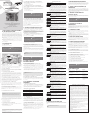 1
1
-
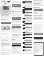 2
2


PPA Triflex Connect Ind Manual do usuário
- Tipo
- Manual do usuário
em outras línguas
- español: PPA Triflex Connect Ind Manual de usuario
- English: PPA Triflex Connect Ind User manual
Artigos relacionados
-
 PPA Triflex Connect Fullrange Dupla Manual do usuário
-
 PPA Trava Dog Steel Manual do proprietário
-
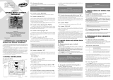 PPA Triflex Connect Brushless Manual do proprietário
-
 PPA Triflex Connect Ind Manual do proprietário
-
 PPA Dz Vantaggio Ind 2000 Jetflex Manual do usuário
-
 PPA Triflex Connect Fullrange Dupla Manual do proprietário
-
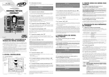 PPA Triflex Connect Manual do proprietário
-
 PPA Giro Dupla Jetflex Manual do proprietário
-
 PPA Triflex Fullrange Display Manual do proprietário
-
 PPA Trava Dog Steel Custom Manual do proprietário


Outros documentos
-
Marantec CBX10224 Manual do proprietário
-
Elvox ES series Manual do usuário
-
Key Gates CT10224 Manual do usuário
-
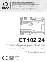 Key Automation 580ISCT10224 Manual do usuário
-
-
 Key Automation 580CT20324W Manual do usuário
-
-
DEA 202RR Manual do proprietário
-

