Dell Vostro 5402 Manual do proprietário
- Categoria
- Cadernos
- Tipo
- Manual do proprietário

Vostro 5402
Service Manual
Regulatory Model: P130G
Regulatory Type: P130G002
January 2021
Rev. A02

Notes, cautions, and warnings
NOTE: A NOTE indicates important information that helps you make better use of your product.
CAUTION: A CAUTION indicates either potential damage to hardware or loss of data and tells you how to avoid
the problem.
WARNING: A WARNING indicates a potential for property damage, personal injury, or death.
© 2020-2021 Dell Inc. or its subsidiaries. All rights reserved. Dell, EMC, and other trademarks are trademarks of Dell Inc. or its subsidiaries.
Other trademarks may be trademarks of their respective owners.

Chapter 1: Working on your computer............................................................................................7
Safety instructions.............................................................................................................................................................. 7
Before working inside your computer....................................................................................................................... 7
Safety precautions........................................................................................................................................................ 8
Electrostatic discharge—ESD protection............................................................................................................... 8
ESD field service kit ..................................................................................................................................................... 9
After working inside your computer........................................................................................................................ 10
Chapter 2: Major components of your system...............................................................................11
Chapter 3: Disassembly and reassembly ...................................................................................... 13
Recommended tools..........................................................................................................................................................13
Screw list..............................................................................................................................................................................13
Base cover........................................................................................................................................................................... 15
Removing the base cover...........................................................................................................................................15
Installing the base cover.............................................................................................................................................16
Battery.................................................................................................................................................................................. 18
Lithium-ion battery precautions............................................................................................................................... 18
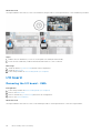
Removing the 3-cell battery - UMA/discrete....................................................................................................... 19
Installing the 3-cell battery - UMA/discrete.........................................................................................................20
Removing the 4-cell battery - UMA/discrete....................................................................................................... 21
Installing the 4-cell battery - UMA/discrete......................................................................................................... 21
WLAN card..........................................................................................................................................................................22
Removing the WLAN card - UMA........................................................................................................................... 22
Installing the WLAN card - UMA............................................................................................................................. 23
Removing the WLAN card - discrete......................................................................................................................24
Installing the WLAN card - discrete........................................................................................................................25
Memory modules............................................................................................................................................................... 26
Removing the memory modules - UMA................................................................................................................. 26
Installing the memory modules - UMA....................................................................................................................27
Removing the memory modules - discrete............................................................................................................28
Installing the memory modules - discrete..............................................................................................................29
Solid-state drive................................................................................................................................................................. 31
Removing the M.2 2280 solid-state drive - UMA................................................................................................ 31
Installing the M.2 2280 solid-state drive - UMA.................................................................................................. 31
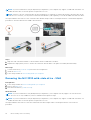
Removing the M.2 2230 solid-state drive - UMA................................................................................................32
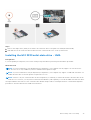
Installing the M.2 2230 solid-state drive - UMA..................................................................................................33
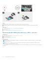
Removing the M.2 2280 solid-state drive - SSD-1 - discrete.......................................................................... 34
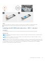
Installing the M.2 2280 solid-state drive - SSD-1 - discrete............................................................................ 35
Removing the M.2 2230 solid-state drive - SSD-1 - discrete.......................................................................... 36
Installing the M.2 2230 solid-state drive - SSD-1 - discrete.............................................................................37
Replacing the SSD-1 support bracket.................................................................................................................... 38
Removing the M.2 2280 solid-state drive - SSD-2 - discrete..........................................................................39
Installing the M.2 2280 solid-state drive - SSD-2 - discrete............................................................................40
Contents
Contents 3

Speakers...............................................................................................................................................................................41
Removing the speakers (in 3-cell battery configuration)...................................................................................41
Installing the speakers (in 3-cell battery configuration).................................................................................... 42
Removing the speakers (in 4-cell battery configuration).................................................................................. 43
Installing the speakers (in 4-cell battery configuration).................................................................................... 44
System fan.......................................................................................................................................................................... 46
Removing the system fan - UMA............................................................................................................................ 46
Installing the system fan - UMA...............................................................................................................................47
Removing the system fan - discrete.......................................................................................................................48
Installing the system fan - discrete.........................................................................................................................49
Heat sink............................................................................................................................................................................. 50
Removing the heat sink - UMA................................................................................................................................50
Installing the heat sink - UMA...................................................................................................................................51
Removing the heat sink - discrete........................................................................................................................... 51
Installing the heat sink - discrete............................................................................................................................ 52
Coin-cell battery................................................................................................................................................................ 53
Removing the coin-cell battery - UMA.................................................................................................................. 53
Installing the coin-cell battery - UMA.................................................................................................................... 54
Removing the coin-cell battery - discrete.............................................................................................................55
Installing the coin-cell battery - discrete...............................................................................................................55
I/O board.............................................................................................................................................................................56
Removing the I/O board - UMA.............................................................................................................................. 56
Installing the I/O board - UMA.................................................................................................................................57
Removing the I/O board - discrete.........................................................................................................................59
Installing the I/O board - discrete...........................................................................................................................60
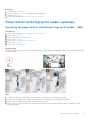
Power button with fingerprint reader (optional)........................................................................................................61
Removing the power button and optional fingerprint reader - UMA.............................................................. 61
Installing the power button with finger reader - UMA....................................................................................... 62
Removing the power button and optional fingerprint reader - discrete........................................................ 63
Installing the power button with finger reader - discrete ................................................................................ 63
DC-in port........................................................................................................................................................................... 64
Removing the DC-in port - UMA.............................................................................................................................64
Installing the DC-in port - UMA............................................................................................................................... 65
Removing the DC-in port - discrete....................................................................................................................... 66
Installing the DC-in port - discrete..........................................................................................................................67
Touchpad.............................................................................................................................................................................68
Removing the touchpad - UMA............................................................................................................................... 68
Installing the touchpad - UMA................................................................................................................................. 69
Removing the touchpad - discrete...........................................................................................................................71
Installing the touchpad - discrete............................................................................................................................ 72
Display assembly................................................................................................................................................................ 73
Removing the display assembly - UMA.................................................................................................................. 73
Installing the display assembly - UMA.................................................................................................................... 75
Removing the display assembly - discrete............................................................................................................ 76
Installing the display assembly - discrete...............................................................................................................79
System board...................................................................................................................................................................... 81
Removing the system board - UMA........................................................................................................................ 81
Installing the system board - UMA..........................................................................................................................83
Removing the system board - discrete..................................................................................................................86
Installing the system board - discrete.................................................................................................................... 88
4
Contents

Palm-rest and keyboard assembly................................................................................................................................. 91
Removing the palm-rest and keyboard assembly - UMA................................................................................... 91
Installing the palm-rest and keyboard assembly - UMA.....................................................................................92
Removing the palm-rest and keyboard assembly - discrete.............................................................................93
Installing the palm-rest and keyboard assembly - discrete............................................................................... 94
Chapter 4: Software....................................................................................................................96
Downloading Windows drivers....................................................................................................................................... 96
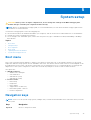
Chapter 5: System setup............................................................................................................. 97
Boot menu........................................................................................................................................................................... 97
Navigation keys..................................................................................................................................................................97
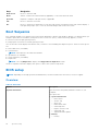
Boot Sequence...................................................................................................................................................................98
BIOS setup..........................................................................................................................................................................98
Overview....................................................................................................................................................................... 98
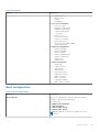
Boot configuration...................................................................................................................................................... 99
Integrated Devices.................................................................................................................................................... 100
Storage..........................................................................................................................................................................101
Display........................................................................................................................................................................... 101
Connection options.................................................................................................................................................... 101
Power management.................................................................................................................................................. 102
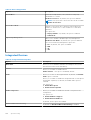
Security........................................................................................................................................................................ 103
Password..................................................................................................................................................................... 104
Update and Recovery............................................................................................................................................... 105
System management................................................................................................................................................ 106
Keyboard...................................................................................................................................................................... 106
Pre-boot behavior......................................................................................................................................................107
Virtualization support................................................................................................................................................108
Performance............................................................................................................................................................... 108
System logs................................................................................................................................................................. 109
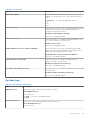
Updating the BIOS in Windows ....................................................................................................................................110
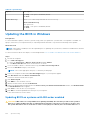
Updating BIOS on systems with BitLocker enabled...........................................................................................110
Updating the Dell BIOS in Linux and Ubuntu environments..............................................................................111
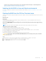
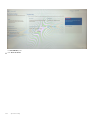
Flashing the BIOS from the F12 One-Time boot menu...................................................................................... 111
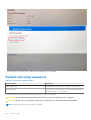
System and setup password..........................................................................................................................................116
Assigning a system setup password.......................................................................................................................117
Deleting or changing an existing system setup password................................................................................ 117
Chapter 6: Troubleshooting........................................................................................................ 118
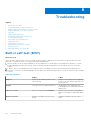
Built-in self-test (BIST).................................................................................................................................................. 118
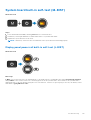
System board built-in self-test (M-BIST).................................................................................................................. 119
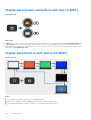
Display panel power rail built-in self-test (L-BIST)............................................................................................ 119
Display panel power rail built-in self-test (L-BIST)................................................................................................. 120
Display panel built-in self-test (LCD-BIST)...............................................................................................................120
Outcome............................................................................................................................................................................. 121
SupportAssist diagnostics.............................................................................................................................................. 121
Running the SupportAssist diagnostics...................................................................................................................... 121
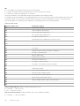
System diagnostic lights................................................................................................................................................. 121
Recovering the operating system................................................................................................................................123
Contents
5

Flashing the BIOS............................................................................................................................................................ 123
Flashing BIOS (USB key)............................................................................................................................................... 123
Backup media and recovery options........................................................................................................................... 124
WiFi power cycle..............................................................................................................................................................124
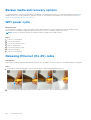
Releasing Ethernet (RJ-45) cable............................................................................................................................... 124
Chapter 7: Getting help..............................................................................................................125
Contacting Dell.................................................................................................................................................................125
6 Contents

Working on your computer
Topics:
• Safety instructions
Safety instructions
Prerequisites
Use the following safety guidelines to protect your computer from potential damage and to ensure your personal safety. Unless
otherwise noted, each procedure included in this document assumes that the following conditions exist:
● You have read the safety information that shipped with your computer.
● A component can be replaced or, if purchased separately, installed by performing the removal procedure in reverse order.
About this task
WARNING: Before working inside your computer, read the safety information that shipped with your computer.
For additional safety best practices information, see the Regulatory Compliance Homepage
CAUTION: Many repairs may only be done by a certified service technician. You should only perform
troubleshooting and simple repairs as authorized in your product documentation, or as directed by the online or
telephone service and support team. Damage due to servicing that is not authorized by Dell is not covered by
your warranty. Read and follow the safety instructions that came with the product.
CAUTION: To avoid electrostatic discharge, ground yourself by using a wrist grounding strap or by periodically
touching an unpainted metal surface at the same time as touching a connector on the back of the computer.
CAUTION: Handle components and cards with care. Do not touch the components or contacts on a card. Hold a
card by its edges or by its metal mounting bracket. Hold a component such as a processor by its edges, not by
its pins.
CAUTION: When you disconnect a cable, pull on its connector or on its pull-tab, not on the cable itself. Some
cables have connectors with locking tabs; if you are disconnecting this type of cable, press in on the locking
tabs before you disconnect the cable. As you pull connectors apart, keep them evenly aligned to avoid bending
any connector pins. Also, before you connect a cable, ensure that both connectors are correctly oriented and
aligned.
NOTE: Disconnect all power sources before opening the computer cover or panels. After you finish working inside the
computer, replace all covers, panels, and screws before connecting to the power source.
NOTE: The color of your computer and certain components may appear differently than shown in this document.
Before working inside your computer
About this task
To avoid damaging your computer, perform the following steps before you begin working inside the computer.
Steps
1. Ensure that you follow the Safety Instruction.
2. Ensure that your work surface is flat and clean to prevent the computer cover from being scratched.
1
Working on your computer 7

3. Turn off your computer.
4. Disconnect all network cables from the computer.
CAUTION: To disconnect a network cable, first unplug the cable from your computer and then unplug the
cable from the network device.
5. Disconnect your computer and all attached devices from their electrical outlets.
6. Press and hold the power button while the computer is unplugged to ground the system board.
NOTE: To avoid electrostatic discharge, ground yourself by using a wrist grounding strap or by periodically touching an
unpainted metal surface at the same time as touching a connector on the back of the computer.
Safety precautions
The safety precautions chapter details the primary steps to be taken before performing any disassembly instructions.
Observe the following safety precautions before you perform any installation or break/fix procedures involving disassembly or
reassembly:
● Turn off the system and all attached peripherals.
● Disconnect the system and all attached peripherals from AC power.
● Disconnect all network cables, telephone, and telecommunications lines from the system.
● Use an ESD field service kit when working inside any notebook to avoid electrostatic discharge (ESD) damage.
● After removing any system component, carefully place the removed component on an anti-static mat.
● Wear shoes with non-conductive rubber soles to reduce the chance of getting electrocuted.
Standby power
Dell products with standby power must be unplugged before you open the case. Systems that incorporate standby power are
essentially powered while turned off. The internal power enables the system to be remotely turned on (wake on LAN) and
suspended into a sleep mode and has other advanced power management features.
Unplugging, pressing and holding the power button for 15 seconds should discharge residual power in the system board. Remove
the battery from notebooks.
Bonding
Bonding is a method for connecting two or more grounding conductors to the same electrical potential. This is done through
the use of a field service electrostatic discharge (ESD) kit. When connecting a bonding wire, ensure that it is connected to bare
metal and never to a painted or non-metal surface. The wrist strap should be secure and in full contact with your skin, and
ensure that you remove all jewelry such as watches, bracelets, or rings prior to bonding yourself and the equipment.
Electrostatic discharge—ESD protection
ESD is a major concern when you handle electronic components, especially sensitive components such as expansion cards,
processors, memory DIMMs, and system boards. Very slight charges can damage circuits in ways that may not be obvious, such
as intermittent problems or a shortened product life span. As the industry pushes for lower power requirements and increased
density, ESD protection is an increasing concern.
Due to the increased density of semiconductors used in recent Dell products, the sensitivity to static damage is now higher than
in previous Dell products. For this reason, some previously approved methods of handling parts are no longer applicable.
Two recognized types of ESD damage are catastrophic and intermittent failures.
● Catastrophic – Catastrophic failures represent approximately 20 percent of ESD-related failures. The damage causes
an immediate and complete loss of device functionality. An example of catastrophic failure is a memory DIMM that has
received a static shock and immediately generates a "No POST/No Video" symptom with a beep code emitted for missing or
nonfunctional memory.
● Intermittent – Intermittent failures represent approximately 80 percent of ESD-related failures. The high rate of
intermittent failures means that most of the time when damage occurs, it is not immediately recognizable. The DIMM
receives a static shock, but the tracing is merely weakened and does not immediately produce outward symptoms related to
8
Working on your computer

the damage. The weakened trace may take weeks or months to melt, and in the meantime may cause degradation of memory
integrity, intermittent memory errors, etc.
The more difficult type of damage to recognize and troubleshoot is the intermittent (also called latent or "walking wounded")
failure.
Perform the following steps to prevent ESD damage:
● Use a wired ESD wrist strap that is properly grounded. The use of wireless anti-static straps is no longer allowed; they do not
provide adequate protection. Touching the chassis before handling parts does not ensure adequate ESD protection on parts
with increased sensitivity to ESD damage.
● Handle all static-sensitive components in a static-safe area. If possible, use anti-static floor pads and workbench pads.
● When unpacking a static-sensitive component from its shipping carton, do not remove the component from the anti-static
packing material until you are ready to install the component. Before unwrapping the anti-static packaging, ensure that you
discharge static electricity from your body.
● Before transporting a static-sensitive component, place it in an anti-static container or packaging.
ESD field service kit
The unmonitored Field Service kit is the most commonly used service kit. Each Field Service kit includes three main components:
anti-static mat, wrist strap, and bonding wire.
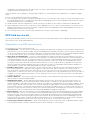
Components of an ESD field service kit
The components of an ESD field service kit are:
● Anti-Static Mat – The anti-static mat is dissipative and parts can be placed on it during service procedures. When using an
anti-static mat, your wrist strap should be snug and the bonding wire should be connected to the mat and to any bare metal
on the system being worked on. Once deployed properly, service parts can be removed from the ESD bag and placed directly
on the mat. ESD-sensitive items are safe in your hand, on the ESD mat, in the system, or inside a bag.
● Wrist Strap and Bonding Wire – The wrist strap and bonding wire can be either directly connected between your wrist
and bare metal on the hardware if the ESD mat is not required, or connected to the anti-static mat to protect hardware that
is temporarily placed on the mat. The physical connection of the wrist strap and bonding wire between your skin, the ESD
mat, and the hardware is known as bonding. Use only Field Service kits with a wrist strap, mat, and bonding wire. Never
use wireless wrist straps. Always be aware that the internal wires of a wrist strap are prone to damage from normal wear
and tear, and must be checked regularly with a wrist strap tester in order to avoid accidental ESD hardware damage. It is
recommended to test the wrist strap and bonding wire at least once per week.
● ESD Wrist Strap Tester – The wires inside of an ESD strap are prone to damage over time. When using an unmonitored
kit, it is a best practice to regularly test the strap prior to each service call, and at a minimum, test once per week. A
wrist strap tester is the best method for doing this test. If you do not have your own wrist strap tester, check with your
regional office to find out if they have one. To perform the test, plug the wrist-strap's bonding-wire into the tester while it is
strapped to your wrist and push the button to test. A green LED is lit if the test is successful; a red LED is lit and an alarm
sounds if the test fails.
● Insulator Elements – It is critical to keep ESD sensitive devices, such as plastic heat sink casings, away from internal parts
that are insulators and often highly charged.
● Working Environment – Before deploying the ESD Field Service kit, assess the situation at the customer location. For
example, deploying the kit for a server environment is different than for a desktop or portable environment. Servers are
typically installed in a rack within a data center; desktops or portables are typically placed on office desks or cubicles. Always
look for a large open flat work area that is free of clutter and large enough to deploy the ESD kit with additional space to
accommodate the type of system that is being repaired. The workspace should also be free of insulators that can cause an
ESD event. On the work area, insulators such as Styrofoam and other plastics should always be moved at least 12 inches or
30 centimeters away from sensitive parts before physically handling any hardware components
● ESD Packaging – All ESD-sensitive devices must be shipped and received in static-safe packaging. Metal, static-shielded
bags are preferred. However, you should always return the damaged part using the same ESD bag and packaging that the
new part arrived in. The ESD bag should be folded over and taped shut and all the same foam packing material should be
used in the original box that the new part arrived in. ESD-sensitive devices should be removed from packaging only at an
ESD-protected work surface, and parts should never be placed on top of the ESD bag because only the inside of the bag is
shielded. Always place parts in your hand, on the ESD mat, in the system, or inside an anti-static bag.
● Transporting Sensitive Components – When transporting ESD sensitive components such as replacement parts or parts
to be returned to Dell, it is critical to place these parts in anti-static bags for safe transport.
Working on your computer
9

ESD protection summary
It is recommended that all field service technicians use the traditional wired ESD grounding wrist strap and protective anti-static
mat at all times when servicing Dell products. In addition, it is critical that technicians keep sensitive parts separate from all
insulator parts while performing service and that they use anti-static bags for transporting sensitive components.
After working inside your computer
About this task
After you complete any replacement procedure, ensure that you connect any external devices, cards, and cables before turning
on your computer.
Steps
1. Connect any telephone or network cables to your computer.
CAUTION: To connect a network cable, first plug the cable into the network device and then plug it into the
computer.
2. Connect your computer and all attached devices to their electrical outlets.
3. Turn on your computer.
4. If required, verify that the computer works correctly by running SupportAssist diagnostics.
10
Working on your computer

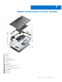
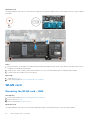
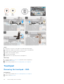
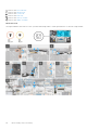
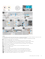
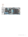
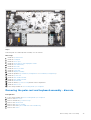
Major components of your system
1. Base cover
2. Battery
3. DC-in port
4. Heat sink
5. Memory module
6. Solid-state drive shield
7. M.2 2230 SSD
8. Speaker
9. System board
10. Touchpad
11. Palm-rest and keyboard assembly
12. Display assembly
13. Power button with fingerprint reader
14. Coin-cell battery
15. I/O board
16. System fan
17. WLAN card
2
Major components of your system 11

18. M.2 2280 SSD
NOTE: Dell provides a list of components and their part numbers for the original system configuration purchased. These
parts are available according to warranty coverages purchased by the customer. Contact your Dell sales representative for
purchase options.
12 Major components of your system

Disassembly and reassembly
NOTE: The images in this document may differ from your computer depending on the configuration you ordered.
Topics:
• Recommended tools
• Screw list
• Base cover
• Battery
• WLAN card
• Memory modules
• Solid-state drive
• Speakers
• System fan
• Heat sink
• Coin-cell battery
• I/O board
• Power button with fingerprint reader (optional)
• DC-in port
• Touchpad
• Display assembly
• System board
• Palm-rest and keyboard assembly
Recommended tools
The procedures in this document may require the following tools:
● Phillips #0 screwdriver
● Phillips #1 screwdriver
● Plastic scribe
NOTE: The #0 screw driver is for screws 0-1, and the #1 screw driver is for screws 2-4.
Screw list
NOTE:
When removing screws from a component, it is recommended to note the screw type, the quantity of screws, and
then place them in a screw storage box. This is to ensure that the correct number of screws and correct screw type is
restored when the component is replaced.
NOTE: Some computers have magnetic surfaces. Ensure that the screws are not left attached to such surface when
replacing a component.
NOTE: Screw color may vary with the configuration ordered.
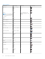
Table 1. Screw list
3
Disassembly and reassembly 13

Table 1. Screw list
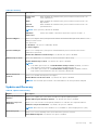
Component Screw type Quantity Screw image
Base cover
M2x8.8 - captive
M2x4
2
5
Battery
NOTE: The 3-cell 40 Whr
battery has 4 screws and 4-
cell 53 Whr battery has 5
screws.
M2x3 4 or 5 depending on the
battery configuration of the
system
WLAN M2x3 1
Solid-state drive -1 M2x3 1
Solid-state drive - 2 M2x3 2
Solid-state drive -2 support
bracket
M1.6x2 1
System fan M2x2 2
Heat sink - UMA M2x5.35 - captive 4
Heat sink - discrete M2x5.35 - captive 7
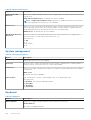
Hinge screws
M2.5x4
M2x3
3
1
I/O board
M2x3 3
Power button with fingerprint
reader
M2x2.5 2
DC-in port
M2x3 1
Touchpad
1.6x2
M2x2
3
2
Display assembly
M2.5x4
M2x3
3
1
14 Disassembly and reassembly

Table 1. Screw list
Component Screw type Quantity Screw image
System board
M2x3 2
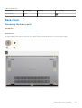
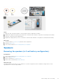
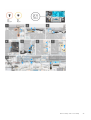
Base cover
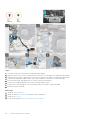
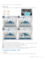
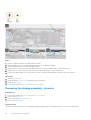
Removing the base cover
Prerequisites
Follow the procedure in before working inside your computer.
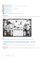
About this task
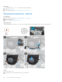
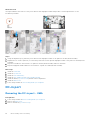
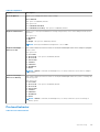
The figure indicates the location of the base cover and provides a visual representation of the removal procedure.
Disassembly and reassembly 15

Steps
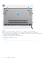
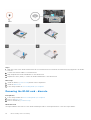
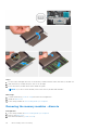
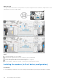
1. Remove the five screws (M2x4) that secure the base cover to the palm-rest and keyboard assembly.
2. Loosen the two captive screws (M2x8.8) that secure the base cover to the palm-rest and keyboard assembly.
3. Pry open the base cover starting from the recess at the hinge area and work your way around and follow the "guidance line"
indicated in the image to remove the base cover.
4. Lift the base cover off the palm-rest and keyboard assembly.
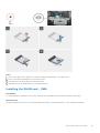
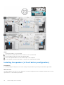
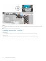
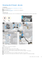
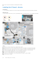
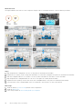
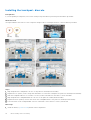
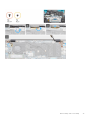
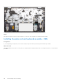
Installing the base cover
Prerequisites
If you are replacing a component, remove the existing component before performing the installation procedure.
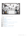
About this task
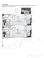
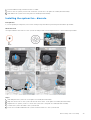
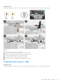
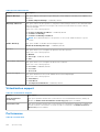
The figure indicates the location of the base cover and provides a visual representation of the installation procedure.
16
Disassembly and reassembly

Disassembly and reassembly 17

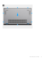
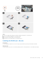
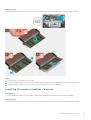
Steps
1. Place the base cover on the palm-rest and keyboard assembly, and snap the base cover into place.
2. Tighten the two captive screws (M2x8.8) that secure the base cover to the palm-rest and keyboard assembly.
3. Replace the five screws (M2x4) that secure the base cover to the palm-rest and keyboard assembly.
Next steps
Follow the procedure in after working inside your computer.
Battery
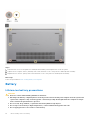
Lithium-ion battery precautions
CAUTION:
● Exercise caution when handling Lithium-ion batteries.
● Discharge the battery completely before removing it. Disconnect the AC power adapter from the system and
operate the computer solely on battery power—the battery is fully discharged when the computer no longer
turns on when the power button is pressed.
● Do not crush, drop, mutilate, or penetrate the battery with foreign objects.
● Do not expose the battery to high temperatures, or disassemble battery packs and cells.
● Do not apply pressure to the surface of the battery.
18 Disassembly and reassembly

● Do not bend the battery.
● Do not use tools of any kind to pry on or against the battery.
● Ensure any screws during the servicing of this product are not lost or misplaced, to prevent accidental
puncture or damage to the battery and other system components.
● If the battery gets stuck inside your computer as a result of swelling, do not try to release it as puncturing,
bending, or crushing a lithium-ion battery can be dangerous. In such an instance, contact Dell technical
support for assistance. See www.dell.com/contactdell.
● Always purchase genuine batteries from www.dell.com or authorized Dell partners and resellers.
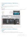
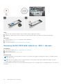
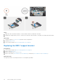
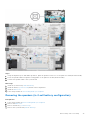
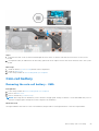
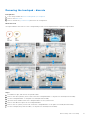
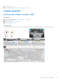
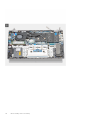
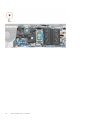
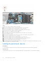
Removing the 3-cell battery - UMA/discrete
Prerequisites
NOTE:
The battery type in your computer varies depending on the configuration ordered.
1. Follow the procedure in before working inside your computer.
2. Remove the base cover.
About this task
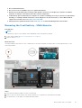
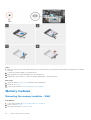
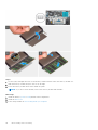
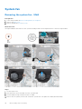
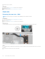
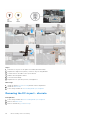
The figure indicates the location of the 3-cell battery in an UMA configuration and provides a visual representation of the
removal procedure.
Steps
1. Disconnect the battery cable from the system board.
2. Remove the four screws (M2x3) that secure the battery to the palm-rest and keyboard assembly.
3. Lift the battery off the palm-rest and keyboard assembly.
Disassembly and reassembly
19

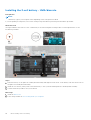
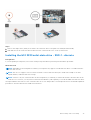
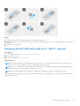
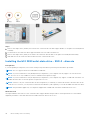
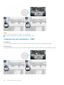
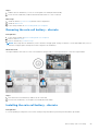
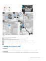
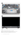
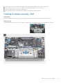
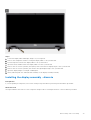
Installing the 3-cell battery - UMA/discrete
Prerequisites
NOTE:
The battery type in your computer varies depending on the configuration ordered.
If you are replacing a component, remove the existing component before performing the installation procedure.
About this task
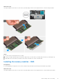
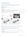
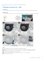
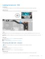
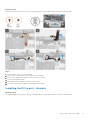
The figure indicates the location of the 3-cell battery in an UMA configuration and provides a visual representation of the
installation procedure.
Steps
1. Place the battery on the palm-rest and keyboard assembly and align the screw holes on the battery with the screw holes on
the palm-rest and keyboard assembly.
2. Install the four screws (M2x3) that secure the battery to the system board and palm-rest and keyboard assembly.
3. Connect the battery cable to the system board.
Next steps
1. Install the base cover.
2. Follow the procedure in after working inside your computer.
20
Disassembly and reassembly
A página está carregando ...
A página está carregando ...
A página está carregando ...
A página está carregando ...
A página está carregando ...
A página está carregando ...
A página está carregando ...
A página está carregando ...
A página está carregando ...
A página está carregando ...
A página está carregando ...
A página está carregando ...
A página está carregando ...
A página está carregando ...
A página está carregando ...
A página está carregando ...
A página está carregando ...
A página está carregando ...
A página está carregando ...
A página está carregando ...
A página está carregando ...
A página está carregando ...
A página está carregando ...
A página está carregando ...
A página está carregando ...
A página está carregando ...
A página está carregando ...
A página está carregando ...
A página está carregando ...
A página está carregando ...
A página está carregando ...
A página está carregando ...
A página está carregando ...
A página está carregando ...
A página está carregando ...
A página está carregando ...
A página está carregando ...
A página está carregando ...
A página está carregando ...
A página está carregando ...
A página está carregando ...
A página está carregando ...
A página está carregando ...
A página está carregando ...
A página está carregando ...
A página está carregando ...
A página está carregando ...
A página está carregando ...
A página está carregando ...
A página está carregando ...
A página está carregando ...
A página está carregando ...
A página está carregando ...
A página está carregando ...
A página está carregando ...
A página está carregando ...
A página está carregando ...
A página está carregando ...
A página está carregando ...
A página está carregando ...
A página está carregando ...
A página está carregando ...
A página está carregando ...
A página está carregando ...
A página está carregando ...
A página está carregando ...
A página está carregando ...
A página está carregando ...
A página está carregando ...
A página está carregando ...
A página está carregando ...
A página está carregando ...
A página está carregando ...
A página está carregando ...
A página está carregando ...
A página está carregando ...
A página está carregando ...
A página está carregando ...
A página está carregando ...
A página está carregando ...
A página está carregando ...
A página está carregando ...
A página está carregando ...
A página está carregando ...
A página está carregando ...
A página está carregando ...
A página está carregando ...
A página está carregando ...
A página está carregando ...
A página está carregando ...
A página está carregando ...
A página está carregando ...
A página está carregando ...
A página está carregando ...
A página está carregando ...
A página está carregando ...
A página está carregando ...
A página está carregando ...
A página está carregando ...
A página está carregando ...
A página está carregando ...
A página está carregando ...
A página está carregando ...
A página está carregando ...
A página está carregando ...
-
 1
1
-
 2
2
-
 3
3
-
 4
4
-
 5
5
-
 6
6
-
 7
7
-
 8
8
-
 9
9
-
 10
10
-
 11
11
-
 12
12
-
 13
13
-
 14
14
-
 15
15
-
 16
16
-
 17
17
-
 18
18
-
 19
19
-
 20
20
-
 21
21
-
 22
22
-
 23
23
-
 24
24
-
 25
25
-
 26
26
-
 27
27
-
 28
28
-
 29
29
-
 30
30
-
 31
31
-
 32
32
-
 33
33
-
 34
34
-
 35
35
-
 36
36
-
 37
37
-
 38
38
-
 39
39
-
 40
40
-
 41
41
-
 42
42
-
 43
43
-
 44
44
-
 45
45
-
 46
46
-
 47
47
-
 48
48
-
 49
49
-
 50
50
-
 51
51
-
 52
52
-
 53
53
-
 54
54
-
 55
55
-
 56
56
-
 57
57
-
 58
58
-
 59
59
-
 60
60
-
 61
61
-
 62
62
-
 63
63
-
 64
64
-
 65
65
-
 66
66
-
 67
67
-
 68
68
-
 69
69
-
 70
70
-
 71
71
-
 72
72
-
 73
73
-
 74
74
-
 75
75
-
 76
76
-
 77
77
-
 78
78
-
 79
79
-
 80
80
-
 81
81
-
 82
82
-
 83
83
-
 84
84
-
 85
85
-
 86
86
-
 87
87
-
 88
88
-
 89
89
-
 90
90
-
 91
91
-
 92
92
-
 93
93
-
 94
94
-
 95
95
-
 96
96
-
 97
97
-
 98
98
-
 99
99
-
 100
100
-
 101
101
-
 102
102
-
 103
103
-
 104
104
-
 105
105
-
 106
106
-
 107
107
-
 108
108
-
 109
109
-
 110
110
-
 111
111
-
 112
112
-
 113
113
-
 114
114
-
 115
115
-
 116
116
-
 117
117
-
 118
118
-
 119
119
-
 120
120
-
 121
121
-
 122
122
-
 123
123
-
 124
124
-
 125
125


Dell Vostro 5402 Manual do proprietário
- Categoria
- Cadernos
- Tipo
- Manual do proprietário
em outros idiomas
- English: Dell Vostro 5402 Owner's manual