
CAUTION: Before using UV System, read this manual and follow all safety rules and operating instructions.
Installation Instructions & Owner’s Manual
Ultraviolet (UV) Water Treatment System
MODELS: VUV-S375B, VUV-S645B, VUV-H375B, VUV-H645B
System tested and certied by NSF
International against NSF/ANSI
Standard 55 and CSA B483.1 for
disinfection performance
190506

Safety InStructIonS:
This Class B system or component conforms to NSF/ANSI Standard 55 and CSA B483.1 for the
supplemental bactericidal treatment of disinfected public drinking water or other drinking water
that has been tested and deemed acceptable for human consumption by the state or local
health agency having jurisdiction. The system is only designed to reduce normally occurring
non-pathogenic nuisance microorganisms. Class B systems are not intended for treatment of
contaminated water.
Congratulations
on purchasing a Vitapur
®
UV Water Treatment System. You have taken the
rst step in ensuring your water is safe for yourself and your family. This system has been designed
to disinfect your water source using UV technology, which has been proven to kill bacteria and
viruses including E. coli, Salmonella, Legionella as well as cysts such as Giardia lamblia and
Cryptosporidium. The Vitapur
®
UV system is a natural non-chemical, environmentally friendly safe
technique for water disinfection treatment that will give you years of peace of mind.
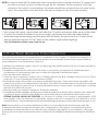
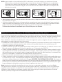
• Do not attempt to install, operate, clean or perform routine maintenance on your
Vitapur® UV system unless you have rst read and understand all of the warnings and
safety instructions that are contained in this manual and on the labels that are afxed to the system.
• Do not attempt to operate the Vitapur® UV system if it has been visibly damaged, (e.g.,
due to shipping) or if it may have sustained damage, (e.g., if the unit has been dropped).
To prevent faulty operation of the system, inspect it carefully to ensure it is free of physical
damage before using.
• Never start your Vitapur® UV system, (e.g., after the initial installation) before conrming
that the exterior is dry and that there are no visible leaks.
• The Vitapur® UV system is designed for indoor applications only and should not be
exposed to outdoor elements.
• Always install and operate the unit in an environment where both the air and water
temperatures will normally range between 36°F (2°C) and 104°F (40°C).
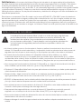
• DANGER: The lamp inside the unit emits ultraviolet light that can cause permanent damage
to skin and eyes. Never look at the lamps when unit is operating.
• Never attempt to operate your Vitapur® UV system unless it has rst been properly grounded,
to avoid creating an electric shock hazard.
• To prevent an electric shock, do not plug the Vitapur® UV system into any socket that has not
been equipped with a Ground Fault Circuit Interrupter (GFCI).
• Always unplug the power cord before attempting to install, clean or perform other routine
maintenance on the unit.
• Always stop the inlet water ow before performing any maintenance on the unit.
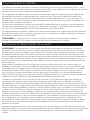
The installation of this system must be in accordance with all provincial/
state and/or local laws and regulations regarding plumbing and electrical
services. Installation by a certied plumber is recommended. Always
comply with the following warnings and safety instructions, to prevent
bodily harm, injury or property damage.

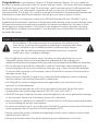
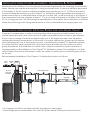
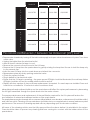
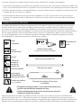
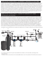
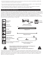
Product overvIew:
The Vitapur
®
Ultraviolet (UV) Water Treatment System has been engineered to rigid standards, and
has been quality inspected at the factory prior to packaging. Please review this manual in its entirety
for a detailed system explanation, and ensure that the following components accompany this
system: To ensure system performance, all replacement components should be purchased directly
from an authorized dealer or directly from GHP Group Inc. (www.ghpgroupinc.com). The use of
components purchased from other sources will void the warranty, and will potentially cause the
system to function in a lesser capacity than intended.
• Do not attempt to service this unit unless you are an accredited service technician, as personal
injury could result and/or system operation could be detrimentally affected.
• Never operate this unit in an oxygen-rich environment, or within 6 feet (2 meters) of any oxygen
source.
• If temperatures should fall below freezing (0°C / 32°F), drain all water from the unit, drain and
disconnect all plumbing lines, and cap the inlet and outlet ports.
!
Power
(green)
Lamp Failure (red)
!
Power (green)
Lamp Failure
(red)
!
Power
(green)
Lamp Failure
(red)
Owners Manual
Electronic Ballast
(Includes lamp connector)
UV Lamp
Quartz Sleeve
Stainless Steel UV Reaction Chamber
Power Cord
VuCap
®
UV Cylinder
Mounting
Clamps and
screws
Retaining Nut
Quartz Sleeve
Sealing O-Ring
Hardware Kit
(2 screws, 2 anchors)
!
Power (green)
Lamp Failure (red)
CAUTION: Before using UV System, read this manual and follow all safety rules and operating instructions.
Installation Instructions & Owner’s Manual
Ultraviolet (UV) Water Treatment System
MODEL: VUV-S375B, VUV-S645B, VUV-H375B, VUV-H645B
System tested and certied by NSF
International against NSF/ANSI
Standard 55 and CSA B483.1 for
disinfection performance
181213
x2
Flow Restrictor
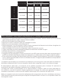
A minimum 5 µ nominal pre-lter is recommended upstream (before) the UV system installation
point. As UV system efciencies are dictated by penetration of the UV light through the water
column, particulate matter within the water column could decrease the disinfection capacity, and
potentially create a harmful condition (ltration systems sold separately).
• Lamps must be replaced after 12 months of operation to ensure
proper disinfection of your water
• Clean Quartz Sleeve frequently for optimum performance

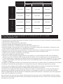
about your SyStem:
* Class B rated ow at least equivalent to 16 mJ/cm
2
water QualIty ParameterS:
Water quality will adversely affect the performance of your Vitapur® UV disinfection system, and the
following levels should be utilized as a guideline for pre-treatment requirements of the inuent water
supply prior to UV treatment:
Iron Total iron count must be less than 0.3 ppm (0.3 mg/L)
Turbidity Count must be less than 1 NTU
Tannins Count must be less than 0.1 ppm (0.1 mg/L)
Manganese Count must be less than 0.05 ppm (0.05mg/L)
Hardness Count must be less than 120 ppm (7 grains per gallon)
%UVT (transmittance) Must be greater than 75%
If you are using untreated surface water or untreated groundwater as your source of supply, the
suitability of the water supply for potable applications must be conrmed by the provincial / state
and/or local health agency that has jurisdiction.
If the test results indicate that: (1) any of the above contaminant levels are being exceeded, or (2)
any prevailing drinking water health standards are not being met, additional pre-treatment options
must be installed that will eliminate all contaminants posing health risks. Non-municipal water should
be tested on an ongoing basis to ensure treatment efciency.
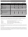
Specifications:
NSF/ANSI Standard 55 Class B and CSA B483.1
Model number: VUV-S375B VUV-S645B VUV-H375B VUV-H645B
Flow Rate GPM US (LPM)
*
7.4 (28.2) 12.3 (46.6) 15.8 (60) 26.4 (100)
Dimensions
Ballast 8” x 3” x 2” (20.3 cm x 7.6 cm x 5.1 cm)
Chamber Diameter 3.5” (8.9 cm) 3.5” (8.9 cm) 3.5” (8.9 cm) 3.5” (8.9 cm)
Chamber Length 17.25” (43.8 cm) 27.88” (70.8 cm) 17.25” (43.8 cm) 27.88” (70.8 cm)
I/O Port Size 3/4” FNPT - 1.0” MNPT
System Maximum Operating Pressure 125psi (862 kPa)
Electrical
Voltage 100-240, 50/60Hz
Power Consumption (W) 21 35 46 67
Lamp Watts (W) 17 30 40 60
Chamber Material 304SS

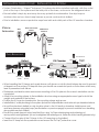
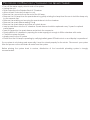
Pro Series
Brine Tank
and Softener
Water Supply
To
Drain
Water
Meter
Shut Off
Valve
Ground
Strap
Optional Bypass Valves
Sediment
Pre Filter
Optional Carbon
Filter
Pro Series
Reverse Osmosis
Water Treatment
GFCI GFCI
Electronic Control
Ballast
UV Chamber
Chambre UV
Cámara UV
Treated
Water
Exits
10 GPM 10 G
Bac à saumure
et adoucisseur
de série Pro
Entrée d’eau
Évacuation
vers le
drain
Compteur
d’eau
Vanne
d’arrêt
Câble de
mise à la
terre
Vannes de dérivation optionnelles
Préfiltre à
sédiments
Filtre à charbon
optionnel
Traitement de
l’eau par osmose
inverse de série Pro
Disjoncteur de
fuite de terre
Disjoncteur de
fuite de terre
Ballast de contrôle
électronique
Sortie
d’eau
traitée
10 GPM 10 G
Ablandador
y tanque
de salmuera
de la serie Pro
Suministro de agua
Drenar
Medidor
de agua
Válvula
de cierre
Banda de
descarga
a tierra
Válvulas de derivación opcionales
Prefiltro
de sedimentos
Filtro de carbono
opcional
Tratamiento
de agua por
osmosis inversa
de la serie Pro
GFCI GFCI
Balasto de control
electrónico
Salida
de agua
tratada
10 GPM 10 G
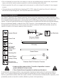
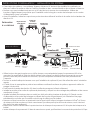
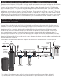
Recommended installation of the Vitapur
®
UV disinfection system is as follows:
* UV chamber should be mounted vertically (see gure on next page).
* Union ttings are recommended in the event UV system needs to be removed from service.
InStallatIon InStructIonS: oPtIonal byPaSS lIne and draIn valve:
To prevent contamination of water in the plumbing, which may pose a health hazard, do not
use the bypass line and valve if your source of supply is untreated surface water or groundwater.
If your source of supply is treated municipal water, use of the bypass line and valve will permit
uninterrupted treated water service in the event of a system malfunction. Always test the bypass
valve following each use of the bypass line, prior to re-starting the Vitapur
®
UV disinfection system
to conrm that the valve has been fully closed and that only water from the outlet port will be
going downstream. The installation of a drain valve, while not required for system operation, is
recommended for all installations of the Vitapur
®
UV disinfection system. The installation of a drain
valve will allow the service technician to drain the system of water prior to conducting any service
on the unit.
InStallatIon InStructIonS: acceSSIbIlIty, orIentatIon & fIttIngS:
Always mount the Vitapur
®
UV in a location that provides ample space for accessing the ultraviolet
lamps. Service may require removing the UV lamp and quartz tube. A minimum distance equivalent
to the length of the UV reaction chamber (stainless steel cylinder) plus 6-12” (15-30cm) is required
to ensure adequate clearance. As the Vitapur
®
UV disinfection system generates heat during use,
please ensure that no combustible items come into contact with, or are in proximity to the system. It
is recommended that you maintain at least 6” (15 cm) of clear wall space on all sides of the Vitapur
®
UV for cooling purposes. This will prolong the operating life of the system. Mount electronic controllers
where they will not get wet during maintenance or from condensation from copper pipes, etc.

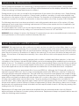
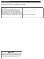
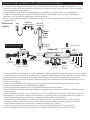
InStallatIon InStructIonS: InStallatIon of SyStem:
• System Orientation – Vitapur
®
Advance UV systems should be installed vertically, with the outlet
port at the top of the system and the inlet port at the base, as shown in the diagrams below.
• Ensure ballast is kept dry and away from any potential condensation. Use drip loops so
moisture does not run down lamp harness or power cord and into ballast.
• Prior to installation, remove protective caps from inlet and outlet ports of the UV reaction chamber.
Electronic Control
Ballast
UV Reaction
Chamber
Treated
Water
Exits
GFCI
Water
Supply
Vertical
installation
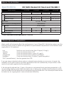
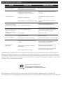
PartS breakdown:
• When handling the UV lamps and quartz sleeves, soft gloves or a cloth should always be used to prevent
oil deposits on the surface. Oil deposits from your hands can create hot spots on the surface which may
lead to premature bulb failure.
• Determine a suitable location and ensure mounting of the UV system in the correct orientation can be
completed.
• Attach the mounting clamp to the installation structure using an appropriate screw type for both the
weight and material of the surface.
• Position the UV reactor chamber into the mounting clamp and secure.
• Install all inlet / outlet plumbing to the system (inclusive of all pre-ltration and valve set-ups described above.
• Mount the electronic ballast in a dry location close to the UV reaction chamber. Install power cord
and lamp harness using drip loops (see illustration on previous page) to prevent moisture from travelling
along cable and into ballast.
• Ensure the quartz sleeve is intact and that the o-ring, VuCap
®
retaining ring and retaining nut
are in position and tightened (do not overtighten the retaining nuts, these should be hand tightened only).
• Connect the four pins of the UV lamp to the UV lamp plug on the ballast.
• Insert the UV lamp into the quartz sleeve and secure the VuCap
®
protective cover.
Ballast
UV Chamber
Power Cord
Mounting
Screws
Wall
Anchor
Lamp Connector
Quartz Sleeve
Spring Inside
Quartz Sleeve
Outlet Port
Inlet Port
Cell Clamps
VuCap
O-Ring
UV Lamp
Retaining Nut
Ground
and Wire
Flow Restrictor

In-HouSe water dIStrIbutIon SyStem dISInfectIon:
The following procedure is recommended for installations of the Vitapur
®
UV disinfection system in a
whole house treatment application. For systems installed on a municipally treated water system, plumbing
system disinfection is at the discretion of the user.
To disinfect the distribution system, carry out the following steps (please ensure that the UV system remains on
during the entire process):
• Familiarize yourself with the various shut-off valves on your system. It is important to understand which
combinations of valve positions allow you to isolate the Vitapur® UV disinfection system
• Shut the main water supply off
• Close the valves necessary to isolate the UV Prelters. Remove the lter cartridge closest to the UV. Fill the
sump with 1-2 cups of household chlorine bleach (5.25%).
• Re-install the sump (without lter) and slowly re-pressurize the system. Open each faucet and allow cold
water to run until you can smell chlorine in the water. Shut off the faucet and repeat with all other household
faucets including hot water. Be sure to include all exterior faucets, shower heads, and dishwasher / washing
machine lines within this process.
• Allow the solution to remain in the lines for 30 minutes minimum.
• Re-install the pre-lter cartridge, and ush each individual water line as above until no chlorine odor is detected.
It is critical to ensure that the water distribution system is fully ushed of all residual chlorine prior to use.
EXTREME CAUTION SHOULD BE EXERCISED. As the level of chlorine in the system is approximately 25-50
times greater than that observed in municipally treated water (this is required for the disinfection of the
household lines). It is extremely important that proper ushing procedures be followed from all taps prior to use.
Note: The introduction of a chlorine disinfection solution to a hot water heater that has been used with
untreated hard water or water with excessive iron, manganese or other organic contaminants may lead
to oxidization of these materials. If you feel that these conditions may apply to your installation, a thorough
ushing of the hot water tank should be done to eliminate the oxidized material from entering the distribution
lines.
1 2 3 4
• Slowly open the supply valves before and after the UV system and ensure there are no water leaks.
• Connect the electronic ballast to the power outlet, and ensure that both the ballast display
(indicates lamp life remaining) and the green LED illuminate. The glow from the UV lamp should
also be visible through the VuCap
®
(May not be visible in high ambient lighting)
Your UV disinfection system is now ready for use.
NOTE: In order to meet NSF 55 certication the ow restrictor that is included with the UV system must
be used to control the ow of water through the UV chamber. The ow restrictor should be
placed on the output. In most settings, the system should have a manual shut off valve at the
input. The water ows in the direction of the arrow located on the ow restrictor label.

The UV system should remain on continuously to ensure protection of your water system. During normal
operation of the system, the green power LED light will be illuminated and the display will indicate the number
of days remaining until lamp replacement is required.
During periods of non-use, it is normal for the temperature of the water in the cylinder to rise. Simply ushing
the water line will alleviate this condition. During humid conditions, sweating, or small water droplets may
be noticed on the surface of the UV reaction chamber. The formation of condensation during high humidity
conditions is normal. Do not allow condensation to drip onto ballast or the Class A system OWL controller.
The following instructions have been provided to assist with general maintenance of the system; UV lamp
replacement and quartz sleeve cleaning/ replacement. All other system repairs must be completed by an
accredited service technician.
For system repairs, rst contact your local water treatment dealer where you purchased this product or an
accredited service technician by calling our Customer Service Center at 1-877-447-4768.
WARNING: Never attempt to service the Vitapur
®
UV system unless you are an accredited service technician,
as the performance of the system could be adversely affected.
WARNING: The lamp heats up after continuous use and can burn your skin if touched. Allow lamp to cool for
at least 5 minutes before removing. Do not operate the UV lamp outside of the reactor. The lamp in the unit
emits powerful Ultraviolet light that can cause permanent damage to skin and eyes. Never look at the lamp
when the unit is turned on. Handle the UV lamp by the ends only. Do not touch the bulb of a lamp with your
ngers. If the surface of the lamp becomes dirty, use a clean lint-free cloth and isopropyl alcohol to remove
the dirt.
Your Vitapur
®
UV disinfection system is equipped with a visible / audible lamp failure indicator. In the event
of a failure of the UV lamp, the red LED light will ash and a loud beeping will be audible from the electronic
ballast of the unit. The lamp life countdown timer will stop decrementing. Please note that if these conditions
occur and you are on a non-municipal supplied water source, you should immediately stop using the water
for potable applications until the lamp is replaced and disinfection of the distribution lines is completed.
The ultraviolet lamp has an approximate life of one year (9000 Hrs.). Although the UV lamp will continue to
operate long past 9000 hours, the UV output continually decreases after 9000 hours, and the UV lamp may
no longer provide adequate disinfection. The built in 365 day countdown timer displays the number of days
remaining until lamp replacement is required. When countdown timer reaches 0 days an intermittent audible
alarm will be activated and display will indicate alarm A3. In order to allow time to obtain a replacement
UV lamp, the audible alarm can be silenced for 7 days by pressing and holding button on ballast for 2-5
seconds. After 7 days, alarm will sound again if lamp has not been replaced. This can be done a maximum of
4 times which allows a total of 28 days to obtain a replacement UV lamp. After 4 times, alarm can no longer
be silenced until a replacement lamp is installed and the lamp life alarm is reset to 365 days by pressing and
holding button for 10 seconds.
Replacement UV lamps and quartz sleeves are available from an authorized dealer. Use only Vitapur
®
approved lamps and sleeves to ensure system performance. Replacement lamps and quartz sleeves are sold
under the following model numbers:
oPeratIon & maIntenance:
lamP InStallatIon and rePlacement:

Procedure for rePlacIng / InStallIng tHe ultravIolet (uv) lamP:
• Depressurize chamber by turning off the inlet water supply and open valve downstream of system. Then close
outlet valve.
• Unplug the ballast from the electrical outlet.
• Allow at least 5 minutes for lamp to cool.
• Remove the connector from the end of the UV lamp.
• Remove the UV lamp from the quartz sleeve by gently rotating the lamp free. Be sure to hold the lamp only
by the ceramic tips.
• Insert the new UV lamp into the quartz sleeve and attach the connector.
• Repressurize system by slowly opening water inlet valve.
• Check the system for leaks.
• Plug in ballast to the electrical outlet.
• Ensure that the UV lamp is operating – the green power LED light should be illuminated, the red lamp failure
LED light should be off and no audible alarm should be active.
• Display will show number of days until lamp replacement is required. If a new lamp was installed. Press and
hold button on ballast for 10 seconds to reset countdown timer.
Mineral deposits and sediment build-up on the quartz sleeve will affect the system performance by decreasing
the UV light transmitted through the quartz sleeve into the water column.
The proper maintenance and replacement of the pre-ltration required for the UV system will reduce the
accumulation of mineral and sediment residue on the quartz sleeve.
The quartz sleeve may be cleaned with a commercially available, non-abrasive, scale remover (should be acidic)
and a lint free cloth. Cleaning of the quartz sleeve should be done on a regular basis to ensure maximum system
performance. The amount of cleaning required will vary depending upon local water conditions.
All traces of the cleaning solution must be fully removed from the sleeve before it is reinstalled in the system.
Care should be taken to prevent any cleaning uid from coming into contact with the inside surface of the
quartz sleeve.
Model #
Replacement Parts
Ballast UV Lamp Quartz Sleeve
S
O
S
E
R
I
E
S
VUV-S375B BA-40S GUVL-330S GQS-330D
VUV-S645B BA-40S GUVL-600S GQS-600D
H
O
S
E
R
I
E
S
VUV-H375B BA-95H GUVL-330H GQS-330D
VUV-H645B BA-95H GUVL-600H GQS-600D

Procedure for removIng / InStallIng tHe Quartz Sleeve:
• Turn off the water supply at both ends of the system.
• Unplug the unit.
• Drain water from the Stainless Steel UV Chamber.
• Allow at least 5 minutes for lamp to cool.
• Remove the connector from the end of the UV lamp.
• Remove the UV lamp from the quartz sleeve by gently rotating the lamp free. Be sure to hold the lamp only
by the ceramic tips.
• Remove the retaining nut securing the quartz sleeve into the chamber
• Remove the quartz sleeve sealing O-ring
• Remove the quartz sleeve and clean as noted above.
• Insert quartz sleeve into the UV chamber. Quartz sleeves should be replaced every 3 years for optimal
performance
• Insert UV lamp into the quartz sleeve and attach the connector.
• Slowly rell the UV chamber by opening the water supply just enough to ll the chamber with water.
• Check the system for leaks.
• Apply power to the UV system
• Ensure that the UV lamp is operating by verifying ballast green LED indicator is on and display is operational
If your system is only being used seasonally, it must be stored properly for the winter. Disconnect your system
from the power source and drain all water from the system.
Before placing the system back in service, disinfection of the household plumbing system is strongly
recommended.

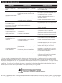
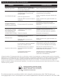
troubleSHootIng guIde:
PROBLEM POSSIBLE CAUSE SUGGESTED SOLUTION
Warm water output
Water sitting in UV reaction chamber
and heating up due to infrequent use
Run tap for a short period of time
Unit leaking water
Misaligned or cross-threaded
connections on inlet / outlet ports
Excessive water pressure
Water hammer* causing pressure spikes
Reinstall to ensure a solid connection
with ports
Install pressure regulator ahead of
system
Install a “Water Hammer” arrestor in
system
No power to UV lamp
when system is plugged
in
GFCI wall socket is tripped
Reset, following manufacturer’s
instructions provided with the outlet
Check socket with other appliances
System has power but UV
lamp is not coming on
(visible / audible alarm
activated)
Lamp not installed correctly
Lamp failure
Ensure lamp is installed correctly with
electrical tting (must be snug)
Replace UV lamp
System is vibrating
Not mounted securely
Water hammer* causing vibrations
Secure fasteners
Install a “Water Hammer” arrestor in system
Excessive heat
generated
Not being allowed sufcient space for
cooling
Operated in an excessive ambient
temperature
Water temperature is too high
Clear space for cooling (min. 6-12” / 15-
30 cm clearance around unit)
Unplug unit until temperature is within
ambient operating conditions
Ensure treatment is on cold water side
only (prior to heating of water)
*Water Hammer: Sudden closure of a control valve or stopping of a pump produces excessive pressure surges in a
pipeline. These pressure surges can cause signicant damage to equipment and/or appliances directly attached to
the water line. Water hammer is usually noted due to the characteristic banging sounds when valves on the line are
suddenly closed. Water hammer conditions must be immediately remedied, and damage to systems as a result of this
condition are not covered under warranty.
If you experience trouble with your system other than the symptoms described above, please visit:
GHP Group Inc. at www.ghpgroupinc.com or contact our Customer Service Department at 1-877-447-4768.
System tested and certied by NSF
International against NSF/ANSI Standard
55 and CSA B483.1 for disinfection performance

nSf data tagS
You must attach the following Class B tag to the UV system.
Class B System:
This system conforms to NSF/ANSI Standard 55 and CSA
B483.1 for the supplemental bactericidal treatment of
disinfected public drinking water or other drinking water
that has been tested and deemed acceptable for human
consumption by the state or local health agency having
jurisdiction. The system is only designed to reduce normally
occurring non-pathogenic nuisance microorganisms.
Class B systems are not intended for the disinfection of
contaminated water.
Always install and operate the unit in an environment
where both air and water temperature will normally range
between 36°F (2°C) and 104°F (40°C).
See instruction manual for use conditions.
Lamp should be replaced every year (9000 Hrs.) Ballast
has built in 365 day countdown timer.
WARNING
This Product can expose you to chemicals including
Diisononyl phthalate (DINP) which is known to the State of
California to cause cancer and Mercury Compounds which is
known to the State of California to cause reproductive harm.
For more information go to www.p65Warnings.ca.gov

Engineered for Health - Designed for Life
Guelph, ON, Canada N1K 1B2
Niles, IL, USA 60714
1-877-447-4768 • www.ghpgroupinc.com

MISE EN GARDE : Lisez attentivement ce guide avant d’utiliser le système UV et respectez toutes les règles de sécurité et les consignes d’utilisation.
Guide d’installation et d’utilisation
Système de traitement d’eau
par ultraviolets (UV)
MODÈLES : VUV-S375B, VUV-S645B,
VUV-H375B, VUV-H645B
Systèmes certiés par NDF International
selon la norme NSF/ANSI 55 et CSA B483.1
concernant le rendement en matière de
désinfection.

conSIgneS de SécurIté
Ce système ou composant de classe B est conforme à la norme NSF/ANSI 55 et CSA B483.1 pour le traitement
bactéricide d’appoint d’eau potable publique désinfectée ou d’autre source d’eau potable préalablement
testée et jugée propre à la consommation humaine par l’État ou par un organisme de santé local compétent.
Le système est conçu pour réduire uniquement la concentration de micro-organismes non pathogènes ou
indésirables normalement présents dans l’eau. Les systèmes de classe B ne sont pas destinés au traitement
de l’eau contaminée.
Nous vous félicitons d’avoir choisi le système de traitement d’eau par UV de Vitapur
®
. Vous avez fait
le premier pas pour vous assurer que votre eau sera sécuritaire pour vous et votre famille. Ce système a
été conçu pour désinfecter votre source d’approvisionnement en eau à l’aide de la technologie UV, dont
l’efcacité a été démontrée pour éliminer les bactéries et virus comme l’E. coli, la Salmonella et la Legionella,
ainsi que les parasites microscopiques tels que la Giardia et le Cryptosporidium. Le système UV de Vitapur
®
fait appel à une technique de traitement de l’eau naturelle, non chimique, écologique et sécuritaire qui
vous permettra d’avoir l’esprit tranquille pendant plusieurs années.
• Ne tentez pas d’installer votre système UV Vitapur®, de le faire fonctionner, de le nettoyer ou d’en
effectuer un entretien périodique avant d’avoir lu et compris l’ensemble des avertissements et des
consignes de sécurité qui gurent dans ce guide et sur les étiquettes apposées sur votre système.
• Ne tentez pas de faire fonctionner le système UV Vitapur® s’il a été visiblement endommagé (p. ex.
lors de l’expédition) ou s’il est susceptible d’avoir subi des dommages (p. ex. si l’appareil a été
échappé). Pour prévenir un mauvais fonctionnement du système, inspectez-le bien avant l’utilisation
pour vous assurer qu’il est exempt de dommages physiques.
• Ne mettez jamais le système UV Vitapur® en marche (p. ex. après l’installation initiale) avant d’avoir
vérié que l’extérieur est sec et qu’il n’y a aucune fuite visible.
• Installez le système UV Vitapur® à l’intérieur et dans un endroit où il ne sera pas exposé aux
intempéries.
• Veuillez toujours installer et faire fonctionner l’appareil dans un milieu où les températures de l’air et
de l’eau oscillent normalement entre 2 °C et 40 °C (36 °F et 104 °F).
• DANGER : La lampe qui se trouve à l’intérieur de l’appareil émet des rayons ultraviolets qui peuvent
causer des lésions permanentes à la peau et aux yeux. Ne regardez jamais la lampe lorsque
l’appareil est en marche.
• Ne tentez jamais de faire fonctionner votre système UV Vitapur® avant qu’il n’ait été mis à la terre
correctement pour éviter tout risque de décharge électrique.
• Pour prévenir les décharges électriques, ne branchez jamais le système UV Vitapur® dans une prise
de courant n’étant pas munie d’un disjoncteur de fuite de terre.
• Débranchez toujours le cordon d’alimentation avant de procéder à l’installation, au nettoyage ou à
tout autre entretien périodique de l’appareil.
L’installation de ce système doit être conforme aux lois et règlements
provinciaux, nationaux et locaux concernant la plomberie et les services
électriques. L’installation par un plombier qualié est recommandée. Veuillez
toujours respecter les consignes de sécurité et les avertissements suivants an
d’éviter les lésions corporelles, les blessures et les dommages matériels.

PréSentatIon du ProduIt
Le système de traitement d’eau par ultraviolets (UV) de Vitapur
®
a été conçu selon des normes strictes
et a été soumis à un contrôle de la qualité en usine avant son conditionnement. Veuillez lire ce guide
en entier pour obtenir des explications détaillées sur le système. Assurez-vous que les pièces illustrées ci-
dessous sont comprises dans l’emballage. Pour assurer le rendement optimal du système, toutes les pièces
de rechange devraient être achetées directement auprès d’un distributeur agréé ou de GHP Group
Inc. (www.ghpgroupinc.com). L’utilisation de pièces achetées ailleurs annulera la garantie et pourrait
éventuellement occasionner une perte d’efcacité du système.
• Fermez toujours la conduite d’arrivée d’eau avant d’effectuer l’entretien de l’appareil.
• Ne tentez pas de réparer vous-même cet appareil à moins que vous ne soyez un technicien qualié, sans
quoi vous pourriez subir des lésions corporelles et le fonctionnement de l’appareil pourrait être compromis.
• Ne faites jamais fonctionner cet appareil dans un environnement riche en oxygène ou dans un rayon de
2 mètres (6 pi) d’une source d’oxygène.
• Si la température descend sous le point de congélation (0 °C/32 °F), évacuez l’eau qui se trouve à
l’intérieur de l’appareil, videz et débranchez toutes les conduites, puis bouchez les orices d’entrée et
de sortie.
!
Power
(green)
Lamp Failure
(red)
!
Power
(green)
Lamp Failure
(red)
!
Power
(green)
Lamp Failure
(red)
Guide
d’utilisation
Ballast électronique
(comprend le connecteur de lampe)
Lampe à rayonnement UV
Manchon en quartz
Chambre de réaction UV en acier
inoxydable
Cordon
d’alimentation
VuCap
®
Colliers de
serrage et
vis pour le
cylindre UV
Écrou de retenue
Joint torique
d’étanchéité pour
manchon en quartz
Trousse de matériel
(2 vis, 2 chevilles)
!
Power (green)
Lamp Failure (red)
CAUTION: Before using UV System, read this manual and follow all safety rules and operating instructions.
Installation Instructions & Owner’s Manual
Ultraviolet (UV) Water Treatment System
MODEL: VUV-S375B, VUV-S645B, VUV-H375B, VUV-H645B
System tested and certied by NSF
International against NSF/ANSI
Standard 55 and CSA B483.1 for
disinfection performance
181213
x2
Réducteur de
débit
Il est recommandé d’installer un préltre nominal d’au moins 5 µ en amont du point d’installation du
système UV (avant celui-ci). L’efcacité du système UV dépend de la pénétration du rayonnement UV
dans la colonne d’eau, c’est pourquoi la présence de particules dans celle-ci peut réduire la capacité de
désinfection et éventuellement créer des conditions nuisibles (systèmes de ltration vendus séparément).
• Remplacez les lampes après 12 mois de fonctionnement pour
garantir une désinfection adéquate de l’eau.
• Nettoyez fréquemment le manchon en quartz pour assurer le
rendement optimal du système.

* Le débit minimum pour la classe B est de 16 mJ/cm
2
.
ParamètreS de la QualIté de l’eau
La qualité de l’eau nuira à l’efcacité de votre système de désinfection UV de Vitapur®. Les mesures
suivantes vous serviront de lignes directrices en ce qui a trait aux exigences de prétraitement de l’eau de
pénétration avant le traitement UV.
Fer La concentration totale de fer doit être inférieure à 0,3 mg/L (0,3 ppm).
Turbidité La turbidité totale de l’eau doit être inférieure à 1 uTN.
Tanins La concentration totale de tanins doit être inférieure à 0,1 mg/L (0,1 ppm).
Manganèse La concentration totale de manganèse doit être inférieure à 0,05 mg/L
(0,05 ppm).
Dureté La dureté totale de l’eau doit être inférieure à 7 grains par gallon (120 ppm).
Transmittance UV (TUV) Le pourcentage de TUV doit être supérieur à 75 %.
Toute eau de surface ou eau souterraine non traitée utilisée comme source d’alimentation doit être jugée
propre à la consommation humaine par un organisme de santé provincial, national ou local compétent.
Des solutions additionnelles de prétraitement doivent être installées pour éliminer les contaminants présentant
des risques pour la santé si les résultats indiquent (1) qu’un des taux de contamination ci-dessus est dépassé,
ou (2) que des normes d’hygiène en vigueur ne sont pas respectées. L’eau non fournie par la municipalité
doit être traitée de façon permanente pour assurer l’efcacité du traitement.
renSeIgnementS Sur votre SyStème
Caractéristiques :
Norme NSF/ANSI 55 classe B et CSA B483.1
Numéro de modèle : VUV-S375B VUV-S645B VUV-H375B VUV-H645B
Débit en L/min [Intl]
(gallon américain par minute)
*
28,2 (7,4) 46,6 (12,3) 60 (15,8) 100 (26,4)
Dimensions
Ballast
20,3 cm x 7,6 cm x 5,1 cm (8 po x 3 po x 2 po)
Diamètre de la chambre
8,9 cm (3,5 po) 8,9 cm (3,5 po) 8,9 cm (3,5 po) 8,9 cm (3,5 po)
Longueur de la chambre
43,8 cm (17,25 po) 70,8 cm (27,88 po) 43,8 cm (17,25 po) 70,8 cm (27,88 po)
Taille de l’orice d’entrée/de sortie
Filetage NPT femelle de 3/4 po – Filetage NPT mâle de 1,0 po
Pression maximale de
fonctionnement du système
862 kPa (125 psi)
Électricité
Tension
100-240 V, 50-60 Hz
Consommation (W)
21 35 46 67
Puissance de la lampe (W)
17 30 40 60
Matériel de la chambre
Acier inoxydable 304

* La chambre de réaction UV peut être installée à la verticale ou à l’horizontale (voir la gure à la
page suivante).
* L’utilisation de raccords unions est recommandée dans le cas où le système UV doit être mis hors service.
InStructIonS d’InStallatIon : conduIte de dérIvatIon et vanne
de draInage facultatIveS
An d’éviter la contamination de l’eau à l’intérieur de la tuyauterie, ce qui pourrait être nocif pour la santé,
n’utilisez pas de conduite de dérivation ni de vanne si votre source d’alimentation est une eau de surface
ou souterraine non traitée. Si votre source d’alimentation est une eau municipale traitée, l’utilisation de la
conduite de dérivation et de la vanne permettra un approvisionnement ininterrompu en eau traitée en cas
de défaillance du système. Testez toujours la vanne de dérivation après chaque utilisation de la conduite
de dérivation et avant de remettre en marche le système de désinfection UV Vitapur
®
an de conrmer
que la vanne est complètement fermée et que seule l’eau de l’orice de sortie peut progresser vers
l’aval. L’installation d’une vanne de drainage, bien que non requise pour le fonctionnement du système,
est recommandée pour toutes les installations du système de désinfection UV de Vitapur
®
. L’installation
d’une vanne de drainage permettra au technicien de vider l’eau du système avant de réparer l’appareil.
L’installation recommandée pour le système de désinfection UV Vitapur
®
est illustrée sur le schéma ci-dessous.
InStructIonS d’InStallatIon : acceSSIbIlIté, orIentatIon et raccordS
Installez toujours le système UV Vitapur
®
dans un endroit qui offre sufsamment d’espace pour accéder aux
lampes à rayonnement UV. Il pourrait être nécessaire de retirer la lampe à rayonnement UV et le tube de
quartz lors de réparations. Une distance minimum équivalente à la longueur de la chambre de réaction UV
(cylindre d’acier inoxydable) plus 15 à 30 cm (6 à 12 po) est requise pour garantir une marge de manœuvre
sufsante. Le système de désinfection UV Vitapur
®
produit de la chaleur lors de l’utilisation, c’est pourquoi il
est important de s’assurer qu’aucun élément combustible n’entre en contact avec celui-ci ou ne soit à sa
proximité. Il est recommandé de maintenir un espace libre minimum de 15 cm (6 po) entre chaque côté
du système UV Vitapur
®
et les murs an qu’il puisse refroidir. La durée de vie du système sera ainsi prolongée.
Installez les régulateurs électroniques à un endroit où ils ne seront pas mouillés durant l’entretien, et où ils
seront à l’abri de la condensation produite par les tuyaux en cuivre, etc.
Pro Series
Brine Tank
and Softener
Water Supply
To
Drain
Water
Meter
Shut Off
Valve
Ground
Strap
Optional Bypass Valves
Sediment
Pre Filter
Optional Carbon
Filter
Pro Series
Reverse Osmosis
Water Treatment
GFCI GFCI
Electronic Control
Ballast
UV Chamber
Chambre UV
Cámara UV
Treated
Water
Exits
10 GPM 10 G
Bac à saumure
et adoucisseur
de série Pro
Entrée d’eau
Évacuation
vers le
drain
Compteur
d’eau
Vanne
d’arrêt
Câble de
mise à la
terre
Vannes de dérivation optionnelles
Préfiltre à
sédiments
Filtre à charbon
optionnel
Traitement de
l’eau par osmose
inverse de série Pro
Disjoncteur de
fuite de terre
Disjoncteur de
fuite de terre
Ballast de contrôle
électronique
Sortie
d’eau
traitée
10 GPM 10 G
Ablandador
y tanque
de salmuera
de la serie Pro
Suministro de agua
Drenar
Medidor
de agua
Válvula
de cierre
Banda de
descarga
a tierra
Válvulas de derivación opcionales
Prefiltro
de sedimentos
Filtro de carbono
opcional
Tratamiento
de agua por
osmosis inversa
de la serie Pro
GFCI GFCI
Balasto de control
electrónico
Salida
de agua
tratada
10 GPM 10 G

InStructIonS d’InStallatIon : InStallatIon du SyStème
• Orientation du système – Les systèmes Vitapur
®
Advance UV doivent être installés à la verticale, en
plaçant l’orice de sortie en haut et l’orice d’entrée en bas, comme illustré sur les schémas ci-dessous.
• Assurez-vous que le ballast reste au sec et à l’abri de toute source de condensation. Utilisez des
boucles d’égouttement pour éviter que l’humidité coule le long du cordon de la lampe ou du cordon
d’alimentation jusqu’au ballast.
• Avant l’installation, retirez les capuchons protecteurs des orices d’entrée et de sortie de la chambre de
réaction UV.
Ballast de
contrôle
électronique
Chambre de
réaction UV
Sortie
d’eau
traitée
Disjoncteur de
fuite de terre
Entrée
d’eau
installation
à la Verticale
lISte deS PIèceS :
• Utilisez toujours des gants souples ou un chiffon lorsque vous manipulez les lampes à rayonnement UV et les
manchons en quartz an d’éviter les dépôts huileux sur la surface. Les dépôts huileux provenant de vos mains
peuvent créer des points chauds sur la surface, qui sont susceptibles d’entraîner une usure prématurée de
l’ampoule
• Trouvez un endroit adéquat et assurez-vous que l’installation du système UV peut être effectuée selon l’orientation
requise.
• À l’aide d’une vis appropriée au poids et au matériau constituant la surface du système, apposez le collier de
serrage à la structure.
• Positionnez la chambre de réaction UV dans le collier de serrage en la xant solidement.
• Installez les entrées et les sorties du système de plomberie (y compris tous les montages de préltration et de vannes
mentionnés ci-haut).
• Installez le ballast électronique dans un endroit sec situé près de la chambre de réaction UV. Fixez le cordon
d’alimentation et le cordon de la lampe en utilisant des boucles d’égouttement (voir l’illustration à la page
précédente) pour éviter que l’humidité coule le long du câble jusqu’au ballast.
• Assurez-vous que le manchon en quartz est intact et que le joint torique, la bague de retenue VuCap
®
et l’écrou
de retenue sont bien en place et vissés correctement (ne serrez pas trop les écrous de retenue, ceux-ci doivent
être vissés à la main seulement).
• Branchez le cordon d’alimentation à quatre broches de la lampe à rayonnement UV à la prise de la lampe sur le
ballast.
• Insérez la lampe à rayonnement UV dans le manchon en quartz, puis xez bien le couvercle de protection VuCap
®
.
Ballast
Chambre UV
Cordon
d’alimentation
Vis de
montage
Dispositif
d’ancrage
au mur
Connecteur de lampe
Manchon
en quartz
Ressort à
l’intérieur
du manchon
en quartz
Orice de sortie
Orice
d’entrée
Colliers de serrage
du cylindre
VuCap
Joint torique
Lampe à
rayonnement
UV
Écrou de retenue
Mise à la
terre et câble
Réducteur de débit

déSInfectIon du SyStème Interne de dIStrIbutIon de l’eau
La procédure suivante est recommandée pour l’installation du système de désinfection UV de Vitapur
®
s’il
est utilisé pour traiter l’eau dans toute la maison. Pour les systèmes installés sur un système d’eau traitée par la
ville, la désinfection est à la discrétion de l’utilisateur.
Pour désinfecter le système de distribution de l’eau, veuillez suivre les étapes ci-dessous (le système UV doit
être en marche tout au long du processus) :
• Familiarisez-vous avec les diverses vannes d’arrêt de votre système. Il est important de comprendre quels
réglages des vannes vous permettent d’isoler le système de désinfection UV de Vitapur®.
• Fermez l’entrée d’eau principale.
• Fermez les vannes nécessaires pour isoler les préltres UV. Retirez la cartouche ltrante la plus près de la
lampe à rayonnement UV. Remplissez le contenant avec 1 à 2 tasses d’eau de Javel domestique (5,25 %).
• Replacez le contenant (sans le ltre) et pressurisez de nouveau le système. Ouvrez tous les robinets et laissez
l’eau froide couler jusqu’à ce qu’une odeur de chlore soit perceptible. Fermez les robinets et recommencez
avec tous les autres robinets de la maison, y compris pour l’eau chaude. Lors de ce processus, n’oubliez pas
les robinets extérieurs, les pommes de douche, le lave-vaisselle et la machine à laver.
• Laissez la solution dans les conduites pour au moins 30 minutes.
• Replacez la cartouche du préltre, puis purgez chaque conduite d’eau mentionnée ci-dessus jusqu’à ce que
l’odeur de chlore ne soit plus perceptible. Avant d’utiliser le système de distribution de l’eau, il est essentiel
de vous assurer qu’il est complètement purgé de tout résidu de chlore. VOUS DEVEZ FAIRE PREUVE D’EXTRÊME
PRUDENCE. Lors de cette procédure, la concentration de chlore est 25 à 50 fois plus élevée que celle
dans l’eau traitée par la ville (c’est nécessaire pour la désinfection des conduites résidentielles). Il est donc
extrêmement important de suivre la procédure de purge à la lettre pour tous les robinets avant de les utiliser.
Remarque : L’inltration d’une solution désinfectante à base de chlore dans un chauffe-eau utilisé avec
de l’eau dure non traitée ou de l’eau présentant une concentration excessive de fer, de manganèse ou
d’autres contaminants organiques pourrait entraîner l’oxydation de ces matériaux. Si vous pensez que ces
cas s’appliquent à vos installations, la purge complète du réservoir à eau chaude devrait être effectuée an
d’empêcher les matériaux oxydés de s’inltrer dans les canalisations de distribution de l’eau.
1 2 3 4
• Ouvrez doucement les vannes d’entrée aux extrémités du système UV et assurez-vous qu’il n’y a pas de
fuites d’eau.
• Branchez le ballast électronique à la prise électrique et assurez-vous que l’écran d’afchage (qui indique
la durée de vie restante de la lampe) et le voyant lumineux à DEL vert sont allumés. La lumière émise par
la lampe à rayonnement UV devrait également être visible à travers le VuCap
®
, à moins que l’éclairage
ambiant ne soit trop fort.
Votre système de désinfection UV est maintenant prêt à l’emploi.
REMARQUE : An de respecter la norme NSF 55, le réducteur de débit compris avec le système UV doit être
utilisé pour contrôler le débit d’eau dans la chambre UV. Le réducteur de débit doit être installé
sur l’orice de sortie. Dans la plupart des cas, le système devrait être doté d’une vanne d’arrêt
manuelle à l’orice d’entrée. L’eau circule dans le sens indiqué par la èche sur l’étiquette du
réducteur de débit.
A página está carregando...
A página está carregando...
A página está carregando...
A página está carregando...
A página está carregando...
A página está carregando...
A página está carregando...
A página está carregando...
A página está carregando...
A página está carregando...
A página está carregando...
A página está carregando...
A página está carregando...
A página está carregando...
A página está carregando...
A página está carregando...
A página está carregando...
A página está carregando...
A página está carregando...
A página está carregando...
-
 1
1
-
 2
2
-
 3
3
-
 4
4
-
 5
5
-
 6
6
-
 7
7
-
 8
8
-
 9
9
-
 10
10
-
 11
11
-
 12
12
-
 13
13
-
 14
14
-
 15
15
-
 16
16
-
 17
17
-
 18
18
-
 19
19
-
 20
20
-
 21
21
-
 22
22
-
 23
23
-
 24
24
-
 25
25
-
 26
26
-
 27
27
-
 28
28
-
 29
29
-
 30
30
-
 31
31
-
 32
32
-
 33
33
-
 34
34
-
 35
35
-
 36
36
-
 37
37
-
 38
38
-
 39
39
-
 40
40


em outras línguas
- español: vitapur VUV-H375B Instrucciones de operación
- français: vitapur VUV-H375B Mode d'emploi
- English: vitapur VUV-H375B Operating instructions
Outros documentos
-
GE GXSM01HWW Manual do usuário
-
Philips WP3890 Manual do usuário
-
-
Sera 08652 Information For Use
-
Kohler K-77685-NA Instruções de operação
-
LG LFX28968ST/03 Manual do proprietário
-
Beckett W5000 Guia de instalação
-
Estate 2315225 Manual do usuário
-
KitchenAid KRFC302EPA Guia de usuario
-
Amana ABB1921BRB Guia de usuario