
ISTRUZIONI PER L'INSTALLAZIONE E LA MANUTENZIONE (IT)
INSTRUCTIONS FOR INSTALLATION AND MAINTENANCE (GB)
INSTRUCTIONS POUR L´INSTALLATION ET LA MAINTENANCE (FR)
INSTALLATIONS- UND WARTUNGSANLEITUNGEN (DE)
INSTRUCTIES VOOR INSTALLATIE EN ONDERHOUD (NL)
INSTRUCCIONES DE INSTALACIÓN Y MANTENIMIENTO (ES)
ИНСТРУКЦИЯ ПО МОНТАЖУ И ТЕХНИЧЕСКОМУ ОБСЛУЖИВАНИЮ (RU)
POKYNY K INSTALACI A ÚDRŽBĚ (CZ)
ASENNUS- JA HUOLTO-OHJEET (FI)
INSTALLATIONS- OCH UNDERHÅLLSANVISNING (SE)
INSTRUCŢIUNI PENTRU INSTALARE ŞI ÎNTREŢINERE (RO)
ΟΔΗΓΙΕΣ ΓΙΑ ΤΗΝ ΕΓΚΑΤΑΣΤΑΣΗ ΚΑΙ ΤΗ ΣΥΝΤΗΡΗΣΗ (GR)
KURMA VE BAKIM BİLGİLERİ (TR)
INSTRUKCJA MONTAŻU I KONSERWACJI (PL)
INSTALLÁCIÓS ÉS KARBANTARTÁSI KÉZIKÖNYV (HU)
INSTRUÇÕES PARA A INSTALAÇÃO E A MANUTENÇÃO (PT)
ИНСТРУКЦИЯ ЗА МОНТИРАНЕ И ПОДДРЪЖКАТА (BG)
(ﺔ
ّ
ﯿ
ِ
ﺑ
َ
ﺮ
َ
ﻌﻟا ﺔﻐﻠﻟا) ﺔﻧﺎﯿﺼﻟاو ﺐﯿﻛﺮﺘﻟا تﺎﻤﯿﻠﻌﺗ
DTRON2

ITALIANO
pag.
01
ENGLISH
page
08
FRANÇAIS
page
15
DEUTSCH
seite
22
NEDERLANDS
pag.
29
ESPAÑOL
pág.
36
РУССКИЙ
стр.
43
ČEŠTINA
strana
50
SUOMI
sivu
57
SVENSKA
sid.
64
ROMÂNĂ
pag.
71
ΕΛΛΗΝΙΚΑ
σελίδα
78
TÜRKÇE
sf.
86
POLSKI
strona
93
MAGYAR
oldal
100
PORTUGUÊS
pag.
107
БЪЛГАРСКИ
Стр.
114
121
ﺔ ﺣ ﻔ ﺻ ﻟ ا
ﺔﻐﻠﻟا ﺔﯾﺑرﻌﻟا

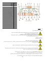
ﻞﻜﺸﻟا Fig. - Fig. – Image - Abb. - Afb. – Fig. - Рис. - Obr. – Kuva – Fig. – Fig. – Εικ. – Şekil – Rys. – Ábra – Fig. – Фиг. -
Fig.1
Fig.2
Fig.3
Fig.5

Fig. 6
Fig. 7
Fig.8
Fig.9

Fig.10
Fig.11

ITALIANO
1
INDICE
AVVERTENZE ........................................................................................................................................................................................ 1
Avvertenze particolari ........................................................................................................................................................................... 2
RESPONSABILITA’ ............................................................................................................................................................................... 2
1 GENERALITA’............................................................................................................................................................................... 2
1.1 Applicazioni ......................................................................................................................................................................... 2
1.2 Liquidi Pompabili ................................................................................................................................................................ 3
1.3 Dati Tecnici .......................................................................................................................................................................... 3
2 INSTALLAZIONE .......................................................................................................................................................................... 4
2.1 Installazione Meccanica ..................................................................................................................................................... 4
3 prima installazione....................................................................................................................................................................... 5
4 funzionalità ................................................................................................................................................................................... 6
4.1 Condizioni di avviamento e arresto pompa ...................................................................................................................... 6
4.2 Pompa On – OFF ................................................................................................................................................................. 6
5 PULIZIA STOCCAGGIO MANUTENZIONE ................................................................................................................................. 7
6 RICERCA GUASTI ........................................................................................................................................................................ 7
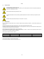
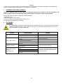
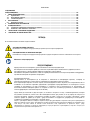
LEGENDA
Nella trattazione sono stati usati i seguenti simboli:
SITUAZIONE DI PERICOLO GENERALE.
Il mancato rispetto delle istruzioni che seguono può causare danni a persone e cose.
SITUAZIONE DI RISCHIO DI SCOSSA ELETTRICA.
Il mancato rispetto delle istruzioni che seguono può causare una situazione di grave pericolo per la sicurezza delle persone.
Note e informazioni generali.
AVVERTENZE
Prima di procedere all’installazione leggere attentamente questa documentazione.
L’installazione ed il funzionamento dovranno essere conformi alla regolamentazione di sicurezza del paese di installazione del
prodotto. Tutta l’operazione dovrà essere eseguita a regola d’arte.
Il mancato rispetto delle norme di sicurezza, oltre a creare pericolo per l’incolumità delle persone e danneggiare le apparecchiature,
farà decadere ogni diritto di intervento in garanzia.
Personale Specializzato
È consigliabile che l’installazione venga eseguita da personale competente e qualificato, in possesso dei requisiti tecnici
richiesti dalle normative specifiche in materia.
Per personale qualificato si intendono quelle
persone che per la loro formazione, esperienza ed istruzione, nonché le
conoscenze delle relative norme, prescrizioni provvedimenti per la prevenzione degli incidenti e sulle condizioni di servizio,
sono stati autorizzati dal responsabile della sicurezza dell’impianto ad eseguire qualsiasi necessaria attività ed in questa essere
in grado di conoscere ed evitare qualsiasi pericolo (Definizione per il personale tecnico IEC 364).
L’apparecchio può essere utilizzato da bambini di età non inferiore a 8 anni e da persone con ridotte capacità fisiche, sensoriali
o mentali, o prive di esperienza o della necessaria conoscenza, purché sotto sorveglianza oppure dopo che le stesse abbiano
ricevuto istruzioni relative all’uso sicuro dell’apparecchio e alla comprensione dei pericoli ad esso inerenti. I bambini non devono
giocare con l’apparecchio. La pulizia e la manutenzione destinata ad essere effettuata dall’utilizzatore non deve essere
effettuata da bambini senza sorveglianza.
Protezione da sovraccarico. La pompa è dotata di un salvamotore termico. In caso di eventuale surriscaldamento del motore, il
salvamotore spegne la pompa automaticamente. Il tempo di raffreddamento è di circa 15-20 min. dopo di che la pompa si
riaccende automaticamente. Dopo l’intervento del salvamotore è assolutamente necessario ricercarne la causa ed eliminarla.
Consultate Ricerca Guasti.

ITALIANO
2
Una mancata osservanza delle avvertenze può creare situazioni di pericolo per le persone o le cose e far decadere la garanzia del prodotto.
Avvertenze particolari
Prima di intervenire sulla parte elettrica o meccanica dell’impianto togliere sempre la tensione di rete. Sono ammissibili
solo allacciamenti di rete saldamente cablati. L’apparecchio deve essere messo a terra (IEC 536 classe 1, NEC ed altri standa
rd
al riguardo).
Morsetti di rete e i morsetti motore possono portare tensione pericolosa anche a motore fermo.
L’apparecchio deve essere utilizzato solamente per le funzioni per le quali è stato costruito.
Sotto determinate condizioni di taratura dopo una caduta di rete il convertitore può partire automaticamente.
RESPONSABILITA’
Il costruttore non risponde del buon funzionamento delle elettropompe o di eventuali danni da queste provocati, qualora le stesse
vengano manomesse, modificate e/o fatte funzionare fuori dal campo di lavoro consigliato o in contrasto con altre disposizioni
contenute in questo manuale.
Declina inoltre ogni responsabilità per le possibili inesattezze contenute nel presente manuale istruzioni, se dovute ad errori di stampa o di
trascrizione. Si riserva il diritto di apportare ai prodotti quelle modifiche che riterrà necessarie od utili, senza pregiudicarne le caratteristiche
essenziali.
1 GENERALITA’
1.1 Applicazioni
Pompa sommersa multistadio con elettronica integrata ideale per l’impiego in sistemi di acqua piovana e reti di irrigazione, per pompare acqua
da serbatoi, cisterne, pozzi, laghetti e per altre applicazioni domestiche che richiedono un’elevata pressione.
Grazie alla forma compatta e maneggevole trovano anche particolari applicazioni come pompe portatili per casi di emergenza quali, prelievo
d‘acqua da serbatoi o fiumi, svuotamento di piscine e fontane. Idonea anche per giardinaggio ed hobbistica in genere.
L’elettronica comanda automaticamente l’accensione e lo spegnimento (ON/OFF) dell’applicazione in funzione della richiesta d’acqua da parte
dell’utilizzatore.
La situazione ideale di lavoro è con la pompa completamente sommersa; tuttavia il sistema di raffreddamento del motore ne consente l’utilizzo
fino all’altezza minima di aspirazione (110 mm).
Il cavo di alimentazione e l’interruttore galleggiante non devono mai essere utilizzati per trasportare o sollevare la pompa.
Utilizzate sempre il manico della pompa.
L’utilizzo è consentito solamente se l’impianto elettrico è contraddistinto da misure di sicurezza secondo le Normative vigenti nel
paese di installazione del prodotto (per l’Italia CEI64/2).
Non staccare mai la spina dalla presa tirando il cavo.
Se il cavo di alimentazione è danneggiato, esso deve essere sostituito dal costruttore o dal suo servizio assistenza tecnica
autorizzato, in modo da prevenire ogni rischio.

ITALIANO
3
Queste pompe non possono essere utilizzate in piscine, stagni, bacini con presenza di persone, e o per il pompaggio di
idrocarburi (benzina, gasolio, oli combustibili, solventi, ecc.) secondo le norme antinfortunistiche vigenti in materia. Prima di
riporle è buona norma prevedere una fase di pulizia (Vedi capitolo “Manutenzione e Pulizia”).
1.2 Liquidi Pompabili
Utilizzare la pompa esclusivamente in acqua pulita.
La pompa non deve essere impiegata per pompare acqua salata, liquami, liquidi infiammabili, corrosivi o esplosivi (es. petrolio,
benzina, diluenti), grassi, oli.
La temperatura del liquido da pompare non deve superare i 50°C (122F)
In caso di utilizzo della pompa per l'alimentazione idrica domestica rispettare le normative locali
delle autorità responsabili della gestione delle risorse idriche.
Dimensioni massima delle particelle solide disperse nel liquido: Diametro 1 mm (0.04 in)
1.3 Dati Tecnici
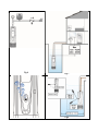
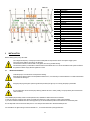
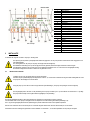
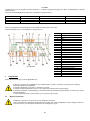
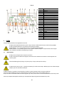
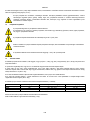
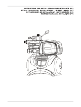
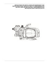
Le pompe DTRON2 sono dotate di un filtro, che a seconda dell’applicazione può essere aperto (vedi figura 1, A) oppure chiuso (chiamato X)
(vedi figura 1, B).
Il filtro aperto impedisce il passaggio di particolati in sospensione aventi diametro superiore a 2.5 mm.
Al suo interno vi è un parzializzatore che impedisce l’aspirazione dal fondo, fino ad un livello di 80mm. E’ possibile tagliare o rimuoverlo per
riuscire ad aspirare acqua fino ad un minimo di 35mm dal fondo. (vedi figura 2).
I prodotti con filtro X sono caratterizzati dalla X a fianco del nome pompa.
Il filtro X è caratterizzata da una base, non stagna, con attacco 1’’ femmina. Il filtro X nasce per essere utilizzato con il KIT X : kit di aspirazione
con galleggiante (vedi figura 3).
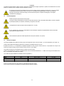
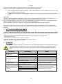
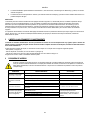
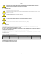
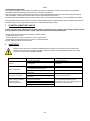
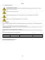
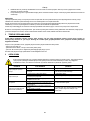
I modelli pompa DTRON2 sono identificati come sotto (Tabella 1):
P1 [W]
Q MAX [l/min – m3/h – gpm]
H MAX [m – psi]
35/90
750
100 – 6 – 26.4
37 – 52.6
45/90
930
105 – 6.3 – 27.7
45 – 64
35/120
900
125 – 7.5 – 33
38 – 54
Tabella 1
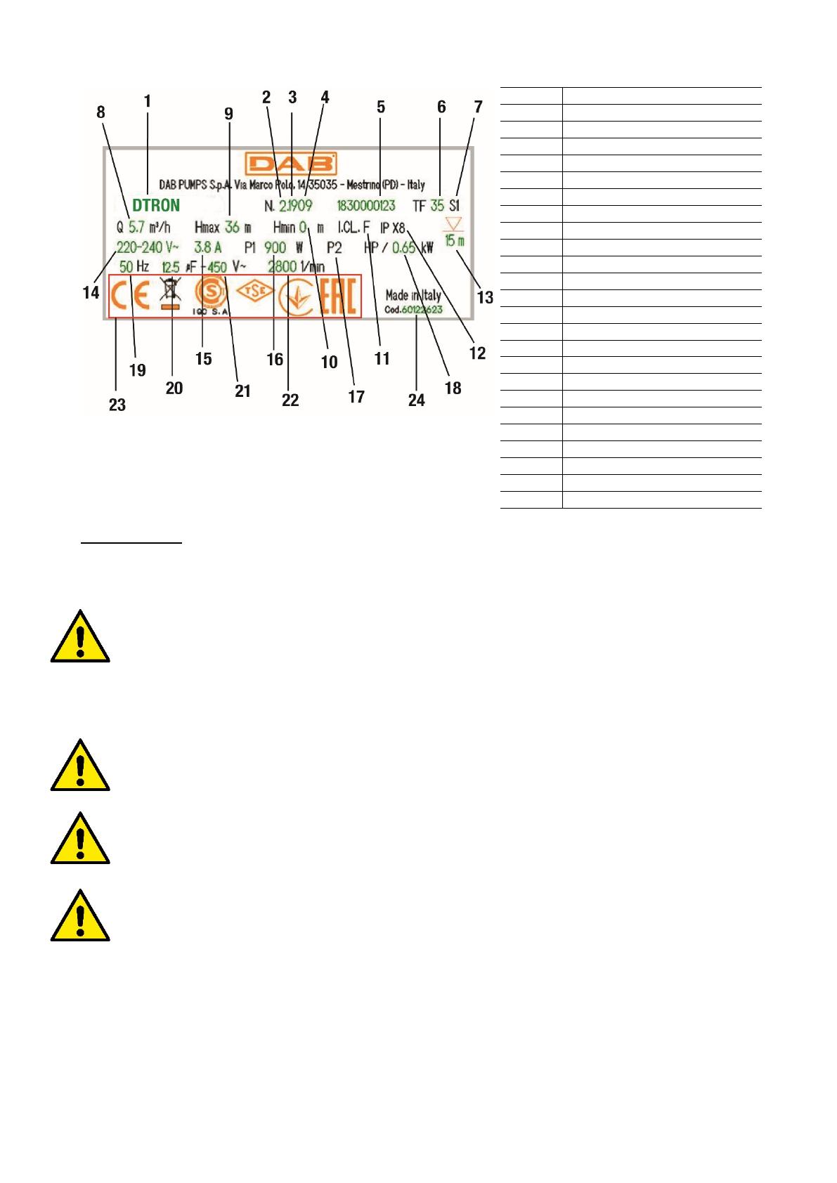
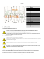
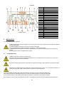
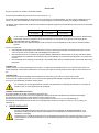
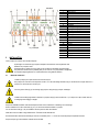
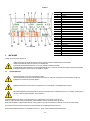
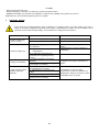
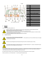
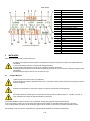
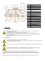
Tutti i dati tecnici sono segnati nell’etichetta tecnica sulla pompa.
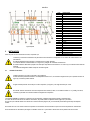
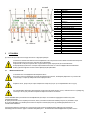
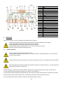
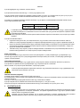
Di seguito la spiegazione delle varie voici presenti (Fig 4) :

ITALIANO
4
Fig.4 Targhetta
Pos.
Descrizione
1
Descrizione
2
Revisione
3
Anno
4
Settimana
5
Numero seriale
6
Massima temperatura del liquido
7
Uso
8
Portata
9
Prevalenza massima
10
Prevalenza minima
11
Classe di isolamento
12
Grado di protezione
13
Sommergibilità
14
Tensione nominale
15
Ampere
16
P1
17
P2 HP
18
P2 kW
19
Frequenza
20
Capacità condensatore
21
Voltaggio
22
N°di giri nominali
23
Loghi
24
Codice pompa
2 INSTALLAZIONE
Prima di mettere in funzione la pompa verificate che:
Il voltaggio e la frequenza riportati sulla targhetta tecnica della pompa corrispondano ai dati dell’impianto elettrico di
alimentazione.
Il cavo di alimentazione della pompa o la pompa non siano danneggiati.
Il collegamento elettrico deve avvenire in luogo asciutto, al riparo di eventuali allagamenti.
L’impianto elettrico sia provvisto di interruttore di protezione salvavita da I ∆n ≤ 30 mA e che l’impianto di terra sia efficiente.
Eventuali prolunghe siano conformi alla normativa vigente
2.1 Installazione Meccanica
Installare la pompa in un luogo non esposto a congelamento.
Quando la pompa rimanga inattiva a temperatura inferiore a 0°C, è necessario assicurarsi che non ci siano residui d’acqua che
ghiacciando possano danneggiarla.
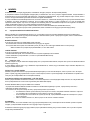
Appendere la pompa passando la corda dall’apposito foro (vedi figura 5). Non appendere la pompa dalla maniglia.
Non installare valvole di ritegno in prossimità della mandata della pompa (cioè a distanza inferiore ad 1 m (3.28ft)). La pompa
infatti presenta già una valvola di ritegno integrata in mandata.
Le pompe DTRON2 contengono già un piccolo vaso di espansione, tarato per colpi di ariete e piccole perdite.
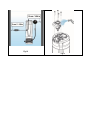
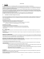
Al fine di diminuire il numero di ripartenze della pompa si può installare un serbatoio ausiliario (Figura 6, A) da 2 litri.
Nel caso si voglia installare un’ulteriore valvola di non ritorno (Figura 6, B) si raccomanda di posizionarla a valle del serbatoio ausiliario.
Non sottoporre il motore ad eccessivi avviamenti/ora. E’ strettamente consigliato di non superare i 60 avviamenti/ora.

ITALIANO
5
È consigliabile l’uso di tubazioni aventi diametro minimo di 1’’, per evitare la diminuzione delle prestazioni della pompa.
La pompa è adatta per installazioni verticali o orizzontali.
Connettere un tubo rigido o flessibile alla mandata della pompa da 1 ¼’’ .
La massima sommergibilità della pompa dipende dalla lunghezza del cavo elettrico: 12m (39.4 ft) in caso di cavo lungo 15m (49.2 ft); 7m (23 ft)
in caso di cavo da 10m (32.8). Controllare il dato a targhetta tecnica, come spiegato in figura 4.
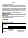
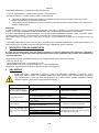
Al fine di garantire sempre un buon affusso di acqua è consigliabile di non superare le seguenti altezze tra i rubinetti di servizio e la pompa
(vedi figura 7).
45/90 35/120 35/90
20 m (65.6 ft) 13 m (42.6 ft) 13 m (42.6 ft)
Per agevolare l’istallazione in cisterna è possibile rimuovere il cavo di alimentazione e/o far passare quest’ultimo da un altro foro
di passaggio. Per rimuoverlo esegiure le indicazioni riportate sulla quick giude del prodotto. Il cavo elettrico è dotato di
connessione rapida.
Far eseguire questa operazione da personale specializzato. Controllare prima della messa in funzione del prodotto l’avvenuta
connessione di terra.
La pompa dispone di:
• Valvola di sfiato per l’aria (vedi figura 8). Questa valvola permette alla pompa di adescare in tempi molto brevi. In caso in cui il livello
dell’acqua sia inferiore del livello della valvola, può fuoriuscire un po' d’acqua dalla valvola di sfiato.
• Piccolo vaso di espansione a molla e membrana (in caso di pompe DTRON2). Questo limita il numero di ripartenze della pompa
compensando piccole perdite dell’impianto stesso. Il vaso protegge la pompa in caso di colpo d’ariete. Il vaso non necessita né di
ricarica né di manutenzione alcuna.
• Una valvola di sovrapressione, che previene il colpo d’ariete. In caso di ghiaccio nel tubo di mandata con pompa sommersa, questa
valvola preserva la pompa da rotture.
Installazione in pozzo.
Installare la pompa in modo che l'aspirazione della pompa si trovi almeno 1 m (3.28ft) sopra il fondo del pozzo per evitare l'aspirazione di sabbia
e impurità. Utilizzare tubi metallici rigidi per appendere la pompa e fissare i tubi con staffe nella parte superiore del pozzo.
Installazione in cisterna
Prevedere che la cisterna di raccolta abbia dimensioni minime per il passaggio pompa di 180x185 mm (7.09x7.28 in).
Tenere leggermente la pompa sollevata dal fondo in modo da evitare possibili rumori/vibrazioni trasmessi alla cisterna.
In caso la pompa venga appoggiata al fondo della cisterna, la pompa produrrà rumore.
Per evitare l’ostruzione dei passaggi di aspirazione, si consiglia di verificare periodicamente che nel pozzetto di raccolta non si
sia accumulato sporco (foglie, sabbia, ecc.).
Installazione con KIT GALLEGGIANTE (accessorio)
In caso di pompe DTRON2, è possibile aggiungere un galleggante di livello NFC.
Questo accessorio, una volta posto nell’apposita sede nella pompa, comunica con la scheda elettronica senza l’ausilio di connessioni elettriche.
Le dimensioni minime di imbombro della pompa con galleggiante all’interno di un pozzo o di una cisterna sono le seguenti:
La distanza consigliata minima tra l’estremità del galleggiante della pompa e la parete è di 3cm (1.18 in) (vedi figura 10).
La distanza consigliata minima tra il galleggiante del tubo di aspirazione (in caso di versione X) è di 10cm (3.94 in) (vedi figura 10).
3 PRIMA INSTALLAZIONE
La pompa e il quadro di comando, se presente, vanno collegate alla stessa rete elettrica, evitando ovvero che siano
galvanicamente separate, come ad esempio a causa della presenza di trasformatori di isolamento o interruttori, anche monofase,
aperti.
In particolari contesti condominiali o industriali, in cui le utenze monofase possono essere collegate a fasi diverse della
distribuzione trifase erogata dal gestore pubblico, il quadro di comando e la pompa potrebbero non riuscire a comunicare.

ITALIANO
6
4 FUNZIONALITÀ
L’elettronica comanda automaticamente l’accensione e lo spegnimento (ON/OFF) della pompa in funzione della richiesta d’acqua.
L’elettronica protegge la pompa dai guasti alla Valvola di Non Ritorno (NRV), presente nel corpo pompa, generalmente causati da incrostazioni
di sporco o di sabbia. Le incrostazioni potrebbero impedire alla NRV di chiudersi, anche in mancanza di acqua. Si raccomanda quindi
un’adeguata manutenzione alla NRV.
La pompa viene spenta automaticamente ogni ora; se tutto è normale, l’utente nota solo un leggerissimo calo di pressione della durata di pochi
secondi. Se invece la NRV è bloccata, la pompa va in allarme e può essere rimessa in funzione dopo aver rimosso le cause dell’ostruzione,
preferibilmente scollegandola e ricollegandola alla rete di alimentazione. L’allarme comunque cessa qualora la valvola si sblocchi
meccanicamente.
L’elettronica protegge la pompa dal funzionamento a secco, ovvero in assenza di acqua (vedi funzione anti-DRYRUN).
L’elettronica protegge la pompa da falsi avvii in caso di gorgoglio dell’acqua (vedi funzione anti-burping).
4.1 Condizioni di avviamento e arresto pompa
Quando si consuma l'acqua nella rete di approvvigionamento idrico, la pompa si avvia quando sono soddisfatte le condizioni di avviamento. Ciò
avviene, ad esempio, aprendo un rubinetto facendo scendere la pressione nell'impianto. La pompa si arresta nuovamente quando il consumo
dell’acqua si arresta, ovvero quando il rubinetto è chiuso.
Condizioni di avviamento
La pompa si avvia quando una delle seguenti condizioni è soddisfatta:
- La portata è superiore alla portata minima di 2 l/min (0.53 gpm).
- La pressione è inferiore alla pressione di avviamento (CUT-IN). Il cut-in è impostato di fabbrica pari a 2.4 bar (34.8 psi).
In caso di pompa dotata di quadro di controllo, il cut-in è variabile.
Condizioni di arresto
La pompa si arresta con un ritardo di 10 secondi quando:
-La portata è inferiore alla portata minima con pressione sopra il CUT-IN.
-La pompa si arresta anche in mancanza di acqua salvaguardando il motore (vedi funzione ANTI DRYRUN)
-Allarmi vari
4.2 Pompa On – OFF
Il motore della pompa è alimentato dalla scheda elettronica di controllo, situata all’interno del corpo pompa, con una tensione alternata pari a
quella dalla rete di distribuzione elettrica.
L’alimentazione della pompa viene erogata al motore in base all’evoluzione delle richieste dell’utente e delle condizioni idrauliche dell’impianto,
come descritto di seguito.
CUT-IN / Flow – Funzionamento normale.
Normalmente (in assenza di allarmi e ad adescamento della pompa ultimato) il motore viene acceso immediatamente se la pressione è inferiore
al cut-in (vedi paragrafo 4.1) oppure in presenza di flusso. Il motore viene spento se la pressione è maggiore del CUTIN e il flusso è assente
(dopo però 10 secondi di permanenza in questa condizione).
Connessione alla rete elettrica - primo adescamento della pompa
Dopo aver connesso la pompa alla rete elettrica, il motore della pompa è spento e la valvola di non ritorno è a riposo: se così non fosse la
pompa si blocca ed il motore non verrà mai avviato (vedi paragrafo ANTIFLOOD).
In caso normale invece, la pompa si comporta come di seguito:
• Se il circuito idraulico a monte della pompa ha una pressione superiore a CUTIN, il motore della pompa non parte, l’adescamento è terminato
regolarmente.
• Se il circuito non è invece in pressione (P<CUT-IN) viene avviato il motore della pompa. In questo caso,
o Se il circuito idraulico va in pressione (P>CUT-IN) e non si ha flusso, ad esempio perché il rubinetto di mandata è chiuso, il
motore viene spento dopo 10 sec dall’avvio: la pompa è adescata.
o Se per 20 secondi non c’è nè flusso nè pressione (P<CUT-IN), la pompa va in allarme DRYRUN e viene spenta: la pompa
non è adescata.
o Infine, se c’è flusso, allora la pompa è adescata e funziona normalmente.
Anti DRYRUN
Se, durante il normale funzionamento (o durante l’avvio della pompa), per 20 secondi non viene rivelata pressione e flusso, la pompa va in
allarme DRYRUN e il motore viene spento.
L’elettronica di controllo della pompa proverà a riavviare la pompa fino a quando la condizione di marcia a secco, ovvero l’assenza di flusso e
pressione, non sarà più riscontrato.

ITALIANO
7
Tali tentativi di riavvio saranno cosi’ schedulati:
• Dal 1° al 48° tentativo: 1 riavvio ogni 30 minuti per 20 secondi ciascuno
• Dal 49° tentativo: 1 riavvio ogni 24 ore per 20 secondi ciascuno
L’allarme DRYRUN può essere resettato manualmente: se in seguito a tale reset la pompa non rivelasse ancora flusso e pressione, i
tentativi dureranno 20 secondi.
L’elettronica della pompa presenta un sistema, detto di anti-burping, che evita i falsi adescamenti legati a possibili gorgoglii dell’acqua.
ANTIFLOOD
La pompa all’avvio mantiene il motore spento per 3 secondi. Se durante questo periodo venisse rivelata la presenza di flusso idraulico, il motore
sarà tenuto spento in quanto potrebbe essere probabile un malfunzionamento meccanico dell’otturatore della pompa.
Per evitare il presentarsi dello stesso problema, che porterebbe ad una accensione indefinita del motore della pompa (in quanto verrebbe
sempre rivelata la presenza di flusso idraulico), durante il normale funzionamento continuativo, il motore verrà spento ogni 60 min.
Se il flusso idraulico non dovesse andare a zero, come ci si aspetta, la pompa va in allarme ANTIFLOOD e il motore della stessa verrà
mantenuto spento.
In presenza di questo allarme la pompa deve essere spenta. Si dovranno risolvere i problemi meccanici occorsi alla valvola di non ritorno. Se la
valvola dovesse comunque meccanicamente sbloccarsi, in seguito ad esempio a vibrazioni del corpo pompa, l’allarme di ANTIFLOOD sarà
rimosso.
5 PULIZIA STOCCAGGIO MANUTENZIONE
La pompa non necessita di manutenzione. Il gelo può danneggiare la pompa. In caso di temperature molto rigide, togliere la pompa
dal liquido, svuotarla e riporla al riparo dal gelo. Prima di effettuare qualsiasi intervento di pulizia, la pompa deve essere scollegata
dalla rete di alimentazione.
E’ consigliabile, una volta che la pompa viene estratta dal liquido, ripulire con semplice getto d’acqua le seguenti parti:
- Filtro (aperto, vedi figura 1A )
- Filtro di aspirazione con galleggiante, in caso di versione X (vedi figura 3)
- Valvola di non ritorno. In questo caso, rimuovere la parte interessata come mostrato in figura 11.
Assicurarsi di rimontare poi tutte le parti nel modo corretto.
6 RICERCA GUASTI
Prima di iniziare la ricerca guasti è necessario interrompere il collegamento elettrico della pompa (togliere la spina dalla presa).
Se il cavo di alimentazione o la pompa in qualsiasi sua parte elettri-
ca è danneggiata l’intervento di riparazione o sostituzione deve essere eseguito dal Costruttore o dal suo servizio di assistenza
tecnica o da una persona con qualifica equivalente in modo da prevenire ogni rischio.
INCONVENIENTI PROBABILI CAUSE RIMEDI
La Pompa non si accende o non
resta accesa.
1. La pompa non è alimentata
1. Verificare alimentazione
2.. Mancanza Acqua 3. Ripristinare il livello dell’acqua
La pompa non eroga acqua
1. La griglia di aspirazione e le tubature sono
ostruite
1. Rimuovere le ostruzioni
2. La girante è usurata o bloccata
2. Sostituire la girante o rimuovere il blocco
3. La prevalenza richiesta è superiore alle
caratteristiche della pompa
La portata è insufficiente
1. La griglia di aspirazione è parzialmente ostruita
1-2 Rimuovere eventuali ostruzioni
2. La girante o il tubo di mandata sono parzialmente
ostruito od incrostati
La pompa si arresta (possibile
intervento dell’interruttore termico
di sicurezza)
1. Il liquido da pompare è troppo denso e
surriscalda il motore.
1-2-3-4 Disinserire la spina e rimuovere la causa che
ha provocato il surriscaldamento, attendere il
raffredamento della spompa e reinserire la spina
2. La temperatura dell’acqua è troppo elevata
3. Un Corpo solido blocca la girante
4. Alimentazione non conforme ai dati di targa

ENGLISH
8
CONTENTS
WARNINGS ............................................................................................................................................................................................ 8
RESPONSIBILITY .................................................................................................................................................................................. 9
1 GENERAL ..................................................................................................................................................................................... 9
1.1 Applications ......................................................................................................................................................................... 9
1.2 Pumpable Liquids ............................................................................................................................................................. 10
1.3 Technical Data ................................................................................................................................................................... 10
2 INSTALLATION........................................................................................................................................................................... 11
2.1 Mechanical Installation ..................................................................................................................................................... 11
3 FIRST INSTALLATION ............................................................................................................................................................... 12
4 FUNCTION .................................................................................................................................................................................. 13
4.1 Pump start and stop conditions ...................................................................................................................................... 13
4.2 Pump On – OFF ................................................................................................................................................................. 13
5 CLEANING STORAGE MAINTENANCE .................................................................................................................................... 14
6 TROUBLESHOOTING ................................................................................................................................................................ 14
KEY
The following symbols have been used in the discussion:
SITUATION OF GENERAL DANGER.
Failure to respect the following instructions may cause damage to persons and property.
SITUATION OF RISK OF ELECTRIC SHOCK.
Failure to respect the following instructions may cause a situation of serious danger for personal safety.
Notes and general information.
WARNINGS
Read this documentation carefully before installation.
Installation and operation must comply with the local safety regulations in force in the country in which the product is installed.
Everything must be done in a workmanlike manner.
Failure to respect the safety regulations not only causes risk to personal safety and damage to the equipment, but invalidates
every right to assistance under guarantee.
Skilled personnel
It is advisable that installation be carried out by competent, skilled personnel in possession of the technical qualifications
required by the specific legislation in force.
The term skilled personnel means persons whose training, experience and instruction, as well as their knowledge of the
respective standards and requirements for accident prevention and working conditions, have been approved by the person in
charge of plant safety, authorizing them to perform all the necessary activities, during which they are able to recognize and
avoid all dangers (Definition for technical personnel IEC 364).
The appliance may be used by children over 8 years old and by persons with reduced physical, sensory or mental capacities, or
who lack experience or knowledge, on condition that they are under supervision or after they have received instructions
concerning the safe use of the appliance and the understanding of the dangers involved. Children must not play with the
appliance. Cleaning and maintenance intended to be carried out by the user must not be performed by children without
supervision.
Overload protection. The pump is equipped with a thermal motor protector. If the motor overheats, the motor protector switches
the pump off automatically. The cooling time is about 15-20 min. after which the pump automatically switches on again. After
the motor protector has tripped, it is absolutely necessary to find the cause and eliminate it. See Troubleshooting.

ENGLISH
9
Failure to observe the warnings may create situations of risk for persons or property and will void the product guarantee.
Particular warnings
Always switch off the mains power supply before working on the electrical or mechanical part of the system. Only firmly
cabled mains connections are admissible. The appliance must be earthed (IEC 536 class 1, NEC and other
applicable
standards).
Mains terminals and motor terminals may still have dangerous voltage when the motor is stopped.
The appliance may only be used for the functions for which it was designed.
Under certain calibration conditions, the converter can start automatically after a power failure.
RESPONSIBILITY
The Manufacturer does not vouch for correct operation of the electropumps or answer for any damage that they may cause if they
have been tampered with, modified and/or run outside the recommended work range or in contrast with other indications given in this
manual.
The Manufacturer declines all responsibility for possible errors in this instructions manual, if due to misprints or errors in copying. The
Manufacturer reserves the right to make any modifications to the products that it may consider necessary or useful, without affecting their
essential characteristics.
1 GENERAL
1.1 Applications
Multistage submerged pump with integrated electronics, ideal for use in rainwater systems and irrigation networks, for pumping water from
tanks, cisterns, wells, lakes and for other domestic applications requiring high pressure.
Thanks to their compact and handy shape, they are also used for particular applications as portable pumps for emergency situations such as for
drawing water from tanks or rivers, draining swimming pools and fountains. Also suitable for gardening and general hobby activity.
The electronics automatically control starting and stopping (ON/OFF) of the application depending on the request for water by the user.
The ideal working situation is with the pump completely submerged; however, the motor cooling system allows its use up to the minimum
suction height (110 mm).
The power supply cable and the float switch must never be used to carry or lift the pump. Always use the pump handle.
Use is allowed only if the electric system is in possession of safety precautions in accordance with the regulations in force in the
country where the product is installed (for Italy CEI64/2).
Never pull on the cable to detach the plug from the socket.
If the power cable is damaged, it must be replaced by the manufacturer or by their authorised technical assistance service, so as
to avoid any risk.

ENGLISH
10
These pumps cannot be used in swimming pools, ponds or basins where people are present, or for pumping hydrocarbons
(petrol, diesel fuel, combustible oils, solvents, etc.) in accordance with the accident-prevention regulations in force. They should
be cleaned before putting them away (See chapter “Maintenance and Cleaning”).
1.2 Pumpable Liquids
Only use the pump in clean water.
The pump must not be used to pump salt water, sewage, inflammable, corrosive or explosive liquids (e.g. petroleum, petrol,
thinners), greases, oils.
The temperature of the liquid to be pumped must not exceed 50°C (122°F).
If the pump is used for the domestic water supply, respect the local regulations of the authorities responsible for the management
of water resources.
Maximum size of solid particles dispersed in the liquid: Diameter 1 mm (0.04 in)
1.3 Technical Data
DTRON2 pumps are equipped with a filter, which can be opened (see figure 1, A) or closed (called X) (see figure 1, B), depending on the
application.
The open filter prevents the passage of suspended particles with a diameter greater than 2.5 mm.
Inside there is a splitter that prevents suction from the bottom, up to a level of 80mm. It is possible to cut or remove it to be able to suck water up
to a minimum of 35mm from the bottom. (see figure 2).
Products with filter X are characterized by the X next to the pump name.
The filter X is characterized by a base, which is not watertight, with a 1'' female connection. The filter X is designed to be used with the KIT X :
suction kit with float (see figure 3).
Pump models DTRON2 are identified as below (Table 1):
P1 [W]
Q MAX [l/min – m3/h – gpm]
H MAX [m – psi]
35/90
750
100 – 6 – 26.4
37 – 52.6
45/90
930
105 – 6.3 – 27.7
45 – 64
35/120
900
125 – 7.5 – 33
38 – 54
Table 1
All technical data are marked on the technical label on the pump.
The various items are explained below (Fig. 4):
ENGLISH
11
Fig.4 Data plate
Pos.
Description
1
Description
2
Revision
3
Year
4
Week
5
Serial number
6
Maximum liquid temperature
7
Use
8
Flow rate
9
Maximum head
10
Minimum head
11
Insulation class
12
Degree of protection
13
Submersibility
14
Rated voltage
15
Ampere
16
P1
17
P2 HP
18
P2 kW
19
Frequency
20
Condenser capacity
21
Voltage
22
Rated number of revolutions
23
Logos
24
Pump code
2 INSTALLATION
Before starting up the pump, check that:
The voltage and frequency on the pump’s technical data plate correspond to the values of the power supply system.
The pump's power cable or the pump is not damaged.
The electrical connection must be made in a dry place, far from any possible flooding.
The electrical system is provided with a residual-current circuit breaker with I ∆n ≤ 30 mA and that the earth system is efficient.
Any extension cables comply with the regulations in force.
2.1 Mechanical Installation
Install the pump in a location that is not exposed to freezing.
When the pump remains inactive at a temperature lower than 0°C, it is necessary to ensure that there is no water residue which
could freeze and damage it.
Hang the pump by passing the rope through the hole provided (see figure 5). Do not hang the pump by the handle.
Do not install check valves near the pump delivery (distance less than 1 metre (3.28ft)). The pump already has a built-in check
valve on delivery.
The DTRON2 pumps already contain a small expansion tank, calibrated for water hammer and small leaks.
In order to reduce the number of pump starts, an auxiliary tank (Figure 6, A) with a capacity of 2 litres can be installed.
If you want to install an additional non return valve (Figure 6, B), it is recommended to position it downstream from the auxiliary tank.
Do not subject the motor to excessive starts per hour. It is strictly recommended not to exceed 60 starts per hour.
It is advisable to use pipes having a minimum diameter of 1’’, to avoid the decrease of pump performance.

ENGLISH
12
The pump is suitable for vertical or horizontal installations.
Connect a rigid or flexible pipe to the 1¼” delivery of the pump.
The maximum submersibility of the pump depends on the length of the power cable: 12m (39.4 ft) in the case of a cable 15m (49.2 ft) long; 7m
(23 ft) in the case of a cable 10m (32.8 ft) long. Check the details on the technical data plate, as shown in figure 4.
In order to always guarantee a good water flow, it is advisable not to exceed the following heights between the service taps and the pump (see
figure 7).
45/90 35/120 35/90
20 m (65.6 ft) 13 m (42.6 ft) 13 m (42.6 ft)
To facilitate installation in the tank, it is possible to remove the power cable and/or pass it through another passage hole. To
remove it, follow the instructions on the product's quick guide. The electrical cable has a quick connection.
Have this operation carried out by qualified personnel. Check the earth connection before commissioning the product.
The pump has:
• An air vent valve (see figure 8). This valve allows the pump to prime in a very short time. If the water level is lower than the valve level,
some water may escape from the vent valve.
• A small spring and diaphragm expansion tank (in the case of DTRON2 pumps). This limits the number of pump restarts and
compensates for small system losses. The tank protects the pump in case of water hammer. The tank does not require any refilling or
maintenance.
• An overpressure valve, which prevents water hammer. In case of ice in the delivery pipe with a submerged pump, this valve protects
the pump from breakage.
Installation in a well.
Install the pump so that the pump suction is at least 1 m (3.28ft) above the bottom of the well to prevent the intake of sand and impurities. Use
rigid metal pipes to hang the pump and secure the pipes with brackets at the top of the well.
Installation in a tank
The minimum dimensions for the pump passage in the collecting tank are 180x185 mm (7.09x7.28 in).
Hold the pump slightly up from the bottom so as to avoid possible noises/vibrations transmitted to the tank.
The pump will make noise if it is placed on the bottom of the tank.
To avoid obstruction of the suction passages, it is recommended to check periodically that no dirt has accumulated in the
collection trap (leaves, sand, etc.).
Installation with FLOAT KIT (accessory)
In the case of DTRON2 pumps, an NFC level float can be added.
This accessory, once placed in the appropriate seat in the pump, communicates with the electronic board without the aid of electrical
connections.
The minimum overall dimensions of the pump with float inside a well or tank are as follows:
The minimum recommended distance between the end of the pump float and the wall is 3cm (1.18 in) (see figure 10).
The minimum recommended distance between the float of the suction pipe and the wall (in the case of version X) is 10cm (3.94 in) (see figure
10).
3 FIRST INSTALLATION
The pump and the control panel, if present, must be connected to the same power mains, avoiding their being galvanically
separated, as for example due to the presence of open isolation transformers or switches, even single-phase ones.
In particular condominium or industrial contexts, where single-phase users can be connected to different phases of the three-
phase distribution provided by the public operator, the control panel and the pump might not be able to communicate.

ENGLISH
13
4 FUNCTION
The electronics automatically control starting and stopping (ON/OFF) of the pump depending on the request for water.
The electronics protect the pump from faults in the Non Return Valve (NRV) in the pump casing, which are generally caused by dirt or sand
deposits. The deposits may prevent the NRV from closing, even in the absence of water. Adequate maintenance of the NRV is therefore
recommended.
The pump is automatically switched off every hour; if everything is normal, the user only notices a very slight drop in pressure lasting a few
seconds. If the NRV is blocked, the pump will go into alarm and can be restarted after removing the causes of the obstruction, preferably by
disconnecting and reconnecting it to the power supply. However, the alarm stops if the valve is released mechanically.
The electronics protect the pump from dry running, that is without water (see anti-DRYRUN function).
The electronics protect the pump from false starts in the event of water bubbling (see anti-burping function).
4.1 Pump start and stop conditions
When water is consumed in the water supply network, the pump starts when the starting conditions are met. This is done, for example, by
turning on a tap and lowering the pressure in the system. The pump stops again when the water consumption stops, that is when the tap is
turned off.
Start conditions
The pump starts when one of the following conditions is met:
- The flow rate is higher than the minimum flow rate of 2 l/min (0.53 rpm).
- The pressure is lower than the starting pressure (CUT-IN). The cut-in is factory set at 2.4 bar (34.8 psi).
If the pump is equipped with a control panel, the cut-in is variable.
Stop conditions
The pump stops with a delay of 10 seconds when:
-The flow rate is lower than the minimum flow rate with pressure above the CUT-IN.
-The pump stops even when there is no water, safeguarding the motor (see ANTI DRYRUN function).
- Various alarms.
4.2 Pump On – OFF
The pump motor is powered by the electronic control board, located inside the pump body, with an alternating voltage equal to that of the
electrical power mains.
The pump power supply is supplied to the motor according to the evolution of the user's requirements and the hydraulic conditions of the
system, as described below.
CUT-IN / Flow – Normal operation
Normally (in the absence of alarms and when the pump has been primed) the motor is switched on immediately if the pressure is lower than the
cut-in (see paragraph 4.1) or if there is flow. The motor is switched off if the pressure is greater than the CUT-IN and the flow is absent
(however, after 10 seconds of permanence in this condition).
Connection to the power mains - first priming of the pump
After connecting the pump to the mains, the pump motor is switched off and the non-return valve is at rest: if this is not the case, the pump stops
and the motor will never start (see ANTIFLOOD paragraph).
In the normal case, however, the pump behaves as follows:
• If the hydraulic circuit upstream from the pump has a pressure higher than CUT-IN, the pump motor does not start, the priming is finished
regularly.
• If the circuit is not under pressure (P<CUT-IN), the pump motor is started. In this case:
o If the hydraulic circuit goes under pressure (P>CUT-IN) and there is no flow, for example because the delivery tap is closed,
the motor is switched off 10 seconds after starting: the pump is primed.
o If there is no flow or pressure for 20 seconds (P<CUT-IN), the pump goes into DRYRUN alarm and is switched off: the pump
is not primed.
o Finally, if there is flow, the pump is primed and runs normally.
Anti DRYRUN
If no pressure and flow is detected during normal operation (or during pump start-up) for 20 seconds, the pump will go into DRYRUN alarm and
the motor will be switched off.
The pump control electronics will try to restart the pump until the dry running condition, i.e. the absence of flow and pressure, is no longer
detected.
These restart attempts will be scheduled as follows:

ENGLISH
14
• From the 1st to the 48th attempt: 1 restart every 30 minutes for 20 seconds each
• From the 49th attempt: 1 restart every 24 hours for 20 seconds each
The DRYRUN alarm can be reset manually: if after this reset the pump still does not detect flow and pressure, attempts will last 20
seconds.
The pump electronics have an anti-burping system that prevents false priming due to possible water bubbles.
ANTIFLOOD
The pump keeps the motor off for 3 seconds when starting. If hydraulic flow is detected during this period, the motor will be kept off as a
mechanical malfunction of the pump shutter may occur.
To avoid the same problem, which would lead to an indefinite start-up of the pump motor (as the presence of hydraulic flow would always be
detected), during normal continuous operation, the motor will be switched off every 60 minutes.
If the hydraulic flow does not go to zero, as expected, the pump goes into ANTIFLOOD alarm and its motor will be kept off.
If this alarm is present, the pump must be switched off. Mechanical problems with the non-return valve must be solved. If the valve is still
mechanically released, e.g. due to vibration of the pump body, the ANTIFLOOD alarm will be removed.
5 CLEANING STORAGE MAINTENANCE
The pump does not require any maintenance. Frost can damage the pump. In very cold temperatures, remove the pump from the
liquid, empty it and store it away from frost. Before any cleaning work is carried out, the pump must be disconnected from the power
mains.
Once the pump has been removed from the liquid, it is advisable to clean the following parts with a simple jet of water:
- Filter (open, see figure 1A)
- Suction filter with float, in case of version X (see figure 3)
- Non-return valve. In this case, remove the part concerned as shown in figure 11.
Be sure to reassemble all parts correctly.
6 TROUBLESHOOTING
Before starting to look for faults it is necessary to disconnect the power supply to the pump (take the plug out of the socket). If the
power cable or any electrical part of the pump is damaged, the repair or replacement must be carried out by the manufacturer or
by their technical assistance service, or by a person with equivalent qualifications, so as to prevent any risk.
FAULTS PROBABLE CAUSES REMEDIES
The pump does not turn on
or does not stay on.
1. Pump is not powered
1. Check power supply
2.. No water 3. Restore the water level
The pump does not deliver
water
1. The suction grid or the pipes are blocked
1. Remove the obstructions
2. The impeller is worn or blocked
2. Replace the impeller or remove the
blockage
3. The head required is higher than the pump’s characteristics
The flow rate is insufficient
1. The suction grid is partly blocked
1-2 Remove any obstructions
2. The impeller or the delivery pipe are partly blocked or encrusted
Pump stops (possible
tripping of the thermal safety
switch)
1. The liquid to be pumped is too thick and overheats the motor.
1-2-3-4 Disconnect the plug and remove the
cause that caused the overheating, wait for
the pump to cool down and reinsert the plug.
2. The water temperature is too high
3. A solid body is blocking the impeller
4. Power supply not in accordance with data plate values

FRANÇAIS
15
SOMMAIRE
MISES EN GARDE ............................................................................................................................................................................... 15
RESPONSABILITÉ .............................................................................................................................................................................. 16
1 CONSIDÉRATIONS GÉNÉRALES ............................................................................................................................................. 16
1.1 Applications ....................................................................................................................................................................... 16
1.2 Liquides Pompables ......................................................................................................................................................... 17
1.3 Données Techniques ........................................................................................................................................................ 17
2 INSTALLATION........................................................................................................................................................................... 18
2.1 Installation Mécanique ...................................................................................................................................................... 18
3 PREMIERE INSTALLATION ....................................................................................................................................................... 19
4 FONCTIONS ................................................................................................................................................................................ 20
4.1 Conditions de démarrage et d'arrêt de la pompe ........................................................................................................... 20
4.2 Pompe On – OFF ............................................................................................................................................................... 20
5 NETTOYAGE RANGEMENT MAINTENANCE ........................................................................................................................... 21
6 DÉPANNAGE .............................................................................................................................................................................. 21
LÉGENDE
Dans ce manuel, les symboles suivants ont été utilisés :
SITUATION DE DANGER GÉNÉRALE
Le non-respect des instructions suivantes peut entraîner des dommages aux personnes et aux biens.
SITUATION DE RISQUE DE CHOC ÉLECTRIQUE.
Le non-respect des instructions suivantes peut entraîner une situation de grave danger pour la sécurité des personnes.
Notes et informations générales
MISES EN GARDE
Avant de procéder à l´installation lire attentivement cette documentation.
L'installation et l'utilisation doivent être conformes aux réglementations de sécurité du pays où le produit est installé. L'ensemble
de l'opération doit être effectué selon les règles de l'art.
Le non-respect des règles de sécurité, en plus de créer un danger pour la sécurité des personnes et des dommages à
l'équipement, annulera tout droit d'intervention sous garantie.
Personnel spécialisé
Nous recommandons que l'installation soit effectuée par du personnel compétent et qualifié, en possession des exigences
techniques requises par la réglementation spécifique en la matière.
Par personnel qualifié, on désigne les personnes qui, du fait de leur formation, de leur expérience et de leur formation, ainsi que
de leur connaissance des réglementations, des dispositions relatives à la prévention des accidents et aux conditions de service
en vigueur, ont été autorisées par le responsable de la sécurité des installations à effectuer toutes les tâches suivantes : toute
activité nécessaire et en ce faire reconnaitre et éviter tout danger (Définition pour le personnel technique CEI 364).
L’appareil peut être utilisé par des enfants de plus de 8 ans et par des personnes ayant des capacités physiques, sensorielles
ou mentales réduites ou avec un manque d’expérience et de connaissances, à condition qu’elles soient surveillées ou après
avoir reçu des instructions sur l’utilisation de l’appareil en toute sécurité et qu’elles ont compris les dangers qui y sont inhérents.
Les enfants ne doivent pas jouer avec l'appareil. Le nettoyage et la maintenance à effectuer par l'utilisateur ne doivent pas être
effectués par des enfants sans surveillance.
Protection contre les surcharges. La pompe est équipée d'un disjoncteur thermique. En cas de surchauffe du moteur, le
disjoncteur arrête automatiquement la pompe. Le temps de refroidissement est d'environ 15-20 min. après quoi la pompe se
rallume automatiquement. Après le déclenchement du disjoncteur, il est absolument nécessaire d’en rechercher la cause la
cause et de l’éliminer. Voir Dépannages.
A página está carregando...
A página está carregando...
A página está carregando...
A página está carregando...
A página está carregando...
A página está carregando...
A página está carregando...
A página está carregando...
A página está carregando...
A página está carregando...
A página está carregando...
A página está carregando...
A página está carregando...
A página está carregando...
A página está carregando...
A página está carregando...
A página está carregando...
A página está carregando...
A página está carregando...
A página está carregando...
A página está carregando...
A página está carregando...
A página está carregando...
A página está carregando...
A página está carregando...
A página está carregando...
A página está carregando...
A página está carregando...
A página está carregando...
A página está carregando...
A página está carregando...
A página está carregando...
A página está carregando...
A página está carregando...
A página está carregando...
A página está carregando...
A página está carregando...
A página está carregando...
A página está carregando...
A página está carregando...
A página está carregando...
A página está carregando...
A página está carregando...
A página está carregando...
A página está carregando...
A página está carregando...
A página está carregando...
A página está carregando...
A página está carregando...
A página está carregando...
A página está carregando...
A página está carregando...
A página está carregando...
A página está carregando...
A página está carregando...
A página está carregando...
A página está carregando...
A página está carregando...
A página está carregando...
A página está carregando...
A página está carregando...
A página está carregando...
A página está carregando...
A página está carregando...
A página está carregando...
A página está carregando...
A página está carregando...
A página está carregando...
A página está carregando...
A página está carregando...
A página está carregando...
A página está carregando...
A página está carregando...
A página está carregando...
A página está carregando...
A página está carregando...
A página está carregando...
A página está carregando...
A página está carregando...
A página está carregando...
A página está carregando...
A página está carregando...
A página está carregando...
A página está carregando...
A página está carregando...
A página está carregando...
A página está carregando...
A página está carregando...
A página está carregando...
A página está carregando...
A página está carregando...
A página está carregando...
A página está carregando...
A página está carregando...
A página está carregando...
A página está carregando...
A página está carregando...
A página está carregando...
A página está carregando...
A página está carregando...
A página está carregando...
A página está carregando...
A página está carregando...
A página está carregando...
A página está carregando...
A página está carregando...
A página está carregando...
A página está carregando...
A página está carregando...
A página está carregando...
A página está carregando...
A página está carregando...
A página está carregando...
-
 1
1
-
 2
2
-
 3
3
-
 4
4
-
 5
5
-
 6
6
-
 7
7
-
 8
8
-
 9
9
-
 10
10
-
 11
11
-
 12
12
-
 13
13
-
 14
14
-
 15
15
-
 16
16
-
 17
17
-
 18
18
-
 19
19
-
 20
20
-
 21
21
-
 22
22
-
 23
23
-
 24
24
-
 25
25
-
 26
26
-
 27
27
-
 28
28
-
 29
29
-
 30
30
-
 31
31
-
 32
32
-
 33
33
-
 34
34
-
 35
35
-
 36
36
-
 37
37
-
 38
38
-
 39
39
-
 40
40
-
 41
41
-
 42
42
-
 43
43
-
 44
44
-
 45
45
-
 46
46
-
 47
47
-
 48
48
-
 49
49
-
 50
50
-
 51
51
-
 52
52
-
 53
53
-
 54
54
-
 55
55
-
 56
56
-
 57
57
-
 58
58
-
 59
59
-
 60
60
-
 61
61
-
 62
62
-
 63
63
-
 64
64
-
 65
65
-
 66
66
-
 67
67
-
 68
68
-
 69
69
-
 70
70
-
 71
71
-
 72
72
-
 73
73
-
 74
74
-
 75
75
-
 76
76
-
 77
77
-
 78
78
-
 79
79
-
 80
80
-
 81
81
-
 82
82
-
 83
83
-
 84
84
-
 85
85
-
 86
86
-
 87
87
-
 88
88
-
 89
89
-
 90
90
-
 91
91
-
 92
92
-
 93
93
-
 94
94
-
 95
95
-
 96
96
-
 97
97
-
 98
98
-
 99
99
-
 100
100
-
 101
101
-
 102
102
-
 103
103
-
 104
104
-
 105
105
-
 106
106
-
 107
107
-
 108
108
-
 109
109
-
 110
110
-
 111
111
-
 112
112
-
 113
113
-
 114
114
-
 115
115
-
 116
116
-
 117
117
-
 118
118
-
 119
119
-
 120
120
-
 121
121
-
 122
122
-
 123
123
-
 124
124
-
 125
125
-
 126
126
-
 127
127
-
 128
128
-
 129
129
-
 130
130
-
 131
131
-
 132
132
-
 133
133


em outras línguas
- français: DAB DTRON 2 Mode d'emploi
- italiano: DAB DTRON 2 Istruzioni per l'uso
- slovenčina: DAB DTRON 2 Návod na používanie
- română: DAB DTRON 2 Instrucțiuni de utilizare
Artigos relacionados
Outros documentos
-
 Agriline Diverton Guia de usuario
-
 Unical FIREX Guia de instalação
-
Comet C 610 HS Manual do usuário
-
 TALLAS D-BOOST 1100/45 115-120V/60Hz Guia de instalação
-
 TALLAS TALLAS D-JET 1100/45 115-120V/60Hz Instruções de operação
-
Trixie Vital Flow Instructions For Use Manual
-
ESAB CC-11 Plasma Coolant Circulator Manual do usuário
-
Vortex BWO 155 Instruções de operação
-
Vortex BWO 155 ZM Instruções de operação
-
Beta 1464TDI Instruções de operação


