
N C
M Y
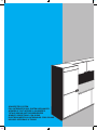
SCHLEPPTÜR SYSTEM
FULL INTEGRATED RAIL SYSTEM APPLIANCES
APPAREILS TOUT INTEGRE A GLISSIERES
TOTALE INBOUW MET DEURGELEIDERS
APARATO EMPOTRADO CON GUI´AS
ELECTRODOME´STICOS INTEGRADOS COM CALHAS
INCASSO INTEGRALE A TRAINO

N C
M Y
ACHTUNG: Teil herausnehmen vor Inbetriebnahme des Gerätes.
WARNING: Remove before connecting the appliance to the socket.
ATTENTION: Enlever avant de mettre l’appareil en fonction.
WAARSCHUWING: Vo´o´r het in gebruiknemen van het apparaat de transportbeveiliging verwijderen.
ATENCIO´N: quitar antes de poner en marcha el aparato.
ATENC¸AO: Retire antes de ligar o electrodome´stico a` corrente ele´ctrica.
ATTENZIONE: Togliere prima di mettere in funzione l’apparecchio.

N C
M Y
Abb.
Fig.
Abb.
Fig.
2
Abb.
Fig.
3
Abb.
Fig.
4
Abb.
Fig.
5
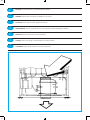
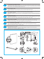
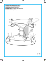
NISCHENMAßE (Abb. 1 - Abb. 2)
Die Rückwand des Geräteumbauschrankes muß,
falls vorhanden, entfernt werden.
(*) Die entsprechende Zahl befindet sich auf dem
Verpackungsaufkleber (Abb. 3).
(**) Für Tiefkühlgefrierschrank.
DIMENSIONS OF THE OPENING (Fig. 1 - Fig. 2)
The rear of the compartment must be left open.
(*) The relevant numbers are indicated on the pac-
kage label (Fig. 3).
(**) For upright freezer.
DIMENSIONS DE LA CAVITE (Fig. 1 - Fig. 2)
La partie arrie`redelade´coupe du meuble doit eˆtre
libre.
(*) Les nume´ros correspondants sont indique´s sur
l’e´tiquette emballage (Fig. 3)
(**) Pour conge´lateur vertical.
AFMETINGEN INBOUWRUIMTE (Fig. 1 - Fig. 2)
Het achterste gedeelte van de inbouwruimte moet
open zijn (schoorsteen ventilatie).
(*) De betreffende nummers staan op het verpak-
kingskarton aangegeven (Fig. 3).
(**) Voor vrieskast.
DIMENSIONES DEL HUECO (Fig. 1 – Fig. 2)
La parte posterior del hueco ha de ser libre.
(*) Los nu´meros correspondientes se indican en la etiqueta
del embalaje (Fig. 3).
(**) Para congelador vertical.
DIMENSOES DO ALOJAMENTO (Fig. 1 – Fig. 2)
A parte de tra´s do alojamento deve ficar livre.
(*) Os nu´meros correspondentes sa˜o indicados na eti-
queta da embalagem (Fig. 3)
(**) Para congelador vertical.
DIMENSIONI DEL VANO (Fig. 1 - Fig. 2)
La parte posteriore del vano deve essere libera.
(*) I numeri corrispondenti sono indicati sul cartellino del-
l’imballo (Fig. 3).
(**) Per congelatore verticale.
REFRIGERATOR / FRIGORIFICO
FRIGORIFICO
FREEZER / CONGELADOR
CONGELADOR
22 (*) AUT
23 (*) E.P. – ***
24 (*) C.V.
L mm 560–568
H mm 876–880 (874 min. – **)
P mm 550 min.
BELÜFTUNG
VENTILATION
VENTILATION
VENTILATIE
VENTILACIO´N
VENTILAC¸AO
VENTILAZIONE

N C
M Y
Abb.
Fig.
6
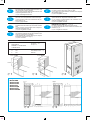
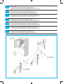
INSTALLATION
Das Gerät in den Geräteumbauschrank schieben (Abb. 6).
Es muß sichergestellt sein, daß das Anschlußkabel nach Einbau des Gerätes jederzeit zugänglich ist, um im Notfall den
Schukostecker herausziehen zu können.
INSTALLATION
ELECTRICAL CONNECTION - Warning: This appliance must be earthed. The colour code and the plug wiring instructions are
specified in the separate operation instructions.
Install the appliance in the housing pushing it against the side opposite to the hinge (Fig. 6).
Please ensure the supply socket is accessible, after installation, in case the appliance needs to be disconnected quickly.
If not possible, connect the appliance to a double-pole switching device with contact separation of at least 3 mm placed in an
accessible position even after installation.
INSTALLATION
Placer l’appareil a` l’inte´rieur de la de´coupe pre´vue a` cet effet dans le meuble de cuisine, en le poussant contre la paroi en bois
oppose´e a` la charnie`re (Fig. 6).
La prise de courant doit rester accessible meˆme apre`s la mise en place de l’appareil, pour permettre de le de´brancher rapidement
en cas de ne´cessite´. Si cela n’est pas possible, pre´voir un dispositif de coupure omnipolaire avec une distance entre les contacts
d’au moins 3 mm restant accessible apre`s l’installation de l’appareil.
INSTALLATIE
Schuif het apparaat in de inbouwruimte, waarbij U erop dient te letten, dat het apparaat tegen de houten wand tegenover het
scharnier geplaatst wordt (Fig. 6).
U dient ervoor te zorgen, dat het stopkontakt te allen tijde bereikbaar is, zodat in geval van nood de stekker onmiddellijk
verwijderd kan worden. Indien dit niet mogelijk is dient U het apparaat door middel van een twee-polige schakelaar met het
voedingsnet te verbinden, waarvan de contacten minstens 3 mm geopend dienen te zijn en welke altijd bereikbaar is.
INSTALACIO´N
Introducir el aparato en la columna acerca´ndolo a la pared de madera opuesta a la pared con bisagra (Fig. 6)
Hay que garantizar el acceso a la toma de corriente del aparato incluso tras su instalacio´n para poder desenchufar la clavija en
caso de necesidad. Si esto no es posible, hay que conectar el aparato a la red mediante un interruptor bipolar con distancia de
apertura de los contactos de 3 mm como mı´nimo, situado en un lugar accesible.
INSTALAC¸AO
Instale o electrodome´stico no respectivo alojamento, empurrando-o na direcc¸a˜o do lado oposto ao da porta (Fig. 6).
Assegure-se de que a tomada fica numa posic¸a˜o acessı´vel, apo´s a instalac¸a˜o, para o caso de ser necessa´rio desligar rapidamente
o electrodome´stico.
Se isso na˜o for possı´vel, ligue o electrodome´stico a um disjuntor bipolar com uma separac¸a˜o de contacto mı´nima de 3 mm., colo-
cado numa posic¸a˜o acessı´vel, mesmo apo´s a instalac¸a˜o.
INSTALLAZIONE
Inserire l’apparecchio nella colonna accostandolo contro la parete in legno opposta alla cerniera (Fig. 6).
Occorre garantire l’accesso alla presa di allacciamento dell’apparecchio anche dopo l’installazione per poter disinserire la spina
in caso di necessita`. Secio` non fosse possibile, collegare l’apparecchio alla rete a mezzo di un interruttore bipolare con distanza di
apertura dei contatti di almeno 3 mm posto in luogo accessibile.
2

N C
M Y
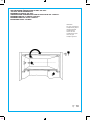
Die Führungen, wie in Abb. 7 gezeigt, am Gerät befestigen. Dazu sind die Befestigungsschrauben aus dem Beipack zu verwenden.
Das Gerät senkrecht und waagrecht ausrichten.
Anschließend ist das Gerät in der Tiefe auszurichten. Die Umbauschranktur ist mittels der Fuhrungsschiene und der im Beipack
befindlichen Schrauben an der Gerätetür anzubringen (Abb. 8). Die richtige Funktion ist durch mehrmaliges Offnen und Schließen
der Tür zu prüfen. Die obere Abdeckung (ebenfalls im Beipack enthalten) ist engegen der Einkerbung im Scharnier provisorisch
anzubringen (Abb. 9). Falls erforderlich, einstellen (wie in Abb. 0).
Secure the rail plates as per Fig. 7, using the parts supplied in the kit.
Adjust the appliance in depth.
Connect the appliance door to the housing door, using the rail guides supplied in the kit (Fig. 8).
Pre-mount the upper plinth (if used) included in the kit as per Fig. 9 in the slot opposite to the hinge. If it is necessary, adjust it as per
Fig. 0.
Fixer les glissie`res suivant la Fig. 7 en utilisant les pie`ces fournies dans l’ensemble de montage.
Re´gler l’appareil en profondeur.
Relier la porte de l’appareil a` la porte de la colonne, en utilisant les glissie`res, livre´es dans l’ensemble de montage (Fig. 8).
Pre´-assembler les enjoliveurs supe´rieur et infe´rieur au moyen des plaquettes fournies (Fig. 9). S’il est necessaire, regler suivant la
Fig. 0.
Bevestig de geleiderplaat, zoals in Fig. 7 staat aangegeven, met behulp van de, in de kit, meegeleverde onderdelen.
Het apparaat zodanig afstellen.
Bevestig de deur van het apparaat aan de deur van het meubel met behulp van de geleider meegeleverd in de kit, zie Fig. 8.
Monteer het boven (indien aanwezig) en onder frontpaneel met behulp van de, in de kit, meegeleverde pluggen, in de gleuven
tegenover het scharnier zoals in Fig. 9 staat afgebeeld. Als het noding, afstellen zoals in Fig. 0.
Fijar las guı´as tal como se ilustra en la Fig. 7 utilizando las piezas suministradas con el kit.
Regular el aparato en profundidad.
Ensamblar la puerta del aparato a la puerta del mueble utilizando las guı´as suministradas en el kit (ve´ase Fig. 8).
Premontar el frontal superior (si se utiliza) y el inferior utilizando los tacos suministrados con el kit, tal como se ilustra en la Fig. 9,
en la ranura opuesta a la bisagra. Si es necesario, regular tal como se ilustra en la Fig. 10.
Fixe as calhas segundo as indicac¸o˜esdaFig.7,usandoaspec¸as fornecidas no kit.
Ajuste o electrodome´stico em profundidade.
Ligue a porta do electrodome´stico a` porta do alojamento, usando as guias da calha fornecidas no kit (Fig. 8).
Realize a pre´-montagem do plinto superior (se existir) incluı´do no kit, conforme a indicac¸o˜es da Fig. 9, no encaixe oposto a` dobra-
dic¸a. Se necessa´rio, ajuste-os conforme o indicado na Fig. 10.
Fissare le guide traino come nella Fig. 7 prelevando i pezzi forniti nel kit.
Regolare l’apparecchio in profondita`.
Collegare la porta dell’apparecchio con la porta del mobile impiegando le guide traino fornite nel kit vedi Fig. 8.
Pre-montare il frontalino superiore (ove impiegato) ed inferiore utilizzando i tasselli forniti nel kit come Fig. 9 nella scanalatura
opposta alla cerniera. Se necessario, regolare come in Fig. 0.
3
48
48
22 mm
1
1
2
1
2
2
4 x 3,9 x 16L
4 x 3,9 x 9,5

N C
M Y
Abb.
Fig.
Abb.
Fig.
2 B
Abb.
Fig.
2 A
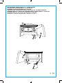
Den oberen Teil des Kühlschranks am Möbel anbringen und dafür die mitgelieferten Schrauben und Buchsen aus dem Montage-
satz verwenden.
Wie auf Abb. 12 A für Möbel H = 876 mit einer Buchse = 9.
Wie auf Abb. 12 B für Möbel H = 880 mit zwei Buchsen H = 6,5.
Den unteren Sookel mit zwei Clipsen anbringen, wie auf Abb. 11 dargestellt.
Fix the top of the refrigerator to the housing, by means of the screws and of the bushes supplied in the kit.
Please refer to Fig. 12 A for housing H = 876 with a bush H = 9.
Please refer to Fig. 12 B for housing H = 880 with two bushes H = 6,5.
Fix the lower plinth by means of the two clips, as illustrated in Fig. 11.
Fixer la partie supe´rieuredure´frige´rateur a` colonne ay moyen des vis et des douilles livre´esdansleKit.
Se re´fe´rer a` la Fig. 12 A pour une colonne H = 875 avec une douille H = 9.
Se re´fe´rer a` la Fig. 12 B pour une colonne H = 880 avec deux douilles H = 6,5.
Fixer la plinthe infe´rieure au moyen des deux clips, suivant la Fig. 11.
Het bovengedeelte van de koelkast aan de kolom vastmaken met behulp van de schroeven en de bussen die in het kit zitten.
Volgens Fig. 12 A voor de kolom H = 876 met een bus H = 9.
Volgens Fig. 12 B voor de kolom H = 880 met twee bussen H = 6,5.
De onderste sokkel met behulp van de twee clips volgens Fig. 11 vastzetten.
Fijar la parte superior del frigorı´fico a la columna poniendo los tornillos y los casquillos suministrados con el kit.
Como en la Fig. 12 A para la columna con H = 876 con casquillo H=9.
Como en la Fig. 12 B para la columna con H = 880 con dos casquillos H=6,5.
Fijar el zo´calo inferior mediante los dos clips tal como se ilustra en la Fig. 11.
Fixe a parte superior do frigorı´fico ao alojamento atrave´s dos parafusos e casquilhos fornecidos no kit.
Consulte a Fig. 12 A para o alojamento H = 876 com um casquilho H = 9.
Consulte a Fig. 12 B para o alojamento H = 880 com dois casquilhos H = 6,5.
Fixe o plinto inferior atrave´s de dois cravos, conforme o ilustrado na Fig. 11.
Fissare la parte superiore del frigorifero alla colonna inserendo le viti e le bussole fornite nel kit.
Come Fig. 12 A per colonna H = 876 con una bussola H = 9.
Come Fig. 12 B per colonna H = 880 con due bussole H = 6,5.
Fissare lo zoccolo inferiore mediante le due clips, come da Figura 11.
4

N C
M Y
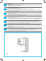
WECHSELBARER TÜRANSCHLAG AN DER “ICE BOX”
“ICE BOX” DOOR REVERSIBILITY
REVERSIBILITE PORTE “ICE BOX”
VERWISSELBARE DRAAIRICHTING VAN DE DEUR VOOR HET “ICE BOX”
REVERSIBILIDAD DE LA PUERTA “ICE BOX”
REVERSIBILIDADE DA PORTA “ICE BOX”
INVERSIONE PORTA “ICE BOX”
Gefrierfach
Ice cube compartment
Compartiment glac¸ons
Vriesvak ijsblokjes
Compartimento
cubitos de hielo
Compartimento para
cubos de gelo
Comparto ghiaccio
Abb.
Fig.
13
5

N C
M Y
WECHSELBARER TÜRANSCHLAG DES 3 - STERNE FACHES
EVAPORATOR DOOR REVERSIBILITY (3 STAR RATED)
REVERSIBILITE PORTE EVAPORATEUR (3 ETOILES)
VERWISSELBARE DRAAIRICHTING VAN DE DEUR VOOR HET 3 STERREN VRIESVAK
REVERSIBILIDAD DE LA PUERTA DEL EVAPORADOR DEL COMPARTIMENTO 3 ESTRELLAS
REVERSIBILIDADE DA PORTA DO EVAPORADOR (3 ESTRELAS)
REVERSIBILITA` PORTA EVAPORATORE COMPARTO 3 STELLE
Abb.
Fig.
14
6

N C
M Y
ÄNDERUNG DES TÜRANSCHLAGES (KÜHL)
DOOR REVERSIBILITY (REFRIGERATOR)
REVERSIBILITE PORTE (REFRIGERATEUR)
OMKEERBAARHEID DEUR (KOELKAST)
REVERSIBILIDAD DE LA PUERTA DEL FRIGORI´FICO
REVERSIBILIDADE DA PORTA
REVERSIBILITA` PORTA (FRIGO)
Abb.
Fig.
15
7

N C
M Y
Printed in Italy 1/05985019 000 0000 (TN)
-
 1
1
-
 2
2
-
 3
3
-
 4
4
-
 5
5
-
 6
6
-
 7
7
-
 8
8
-
 9
9
-
 10
10


em outros idiomas
- español: Whirlpool ARG 417/3 Guía del usuario
- français: Whirlpool ARG 417/3 Mode d'emploi
- italiano: Whirlpool ARG 417/3 Guida utente
- Nederlands: Whirlpool ARG 417/3 Gebruikershandleiding
- Deutsch: Whirlpool ARG 417/3 Benutzerhandbuch

