
1
R. 02/22 850 829
SAMOA Industrial, S.A. · Pol. Ind. Porceyo, I-14 · Camino del Fontán, 831 · 33392 - Gijón - Spain · Tel.: +34 985 381 488 · www.samoaindustrial.com
2022_02_17-13:00
Part. No. / Cód. / Réf. / Art. Nr. /
Cód. / Деталь №:
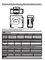
508 8XX SERIES
СЕРИЯ 508 8XX
Parts and technical service guide
Guía de servicio técnico y recambio
Guide d’instructions et pièces de rechange
Bedienungsanleitung und Teileliste
Manual de Serviços Técnicos e Reposições
Список деталей и руководство по техническому обслуживанию
HIGH VOLUME HOSE REELS 2
ENROLLADOR ABIERTO GRAN CAPACIDAD 5
ENROULEUR OUVERT GRAND DÉBIT 8
OFFENER HOCHLEISTUNGS-SCHLAUCHAUFROLLER 11
CARRETEL AUTOMÁTICO, BASE SIMPLES PARA ÁGUA, ÓLEO DIESEL E AR 14
КАТУШКИ СО ШЛАНГОМ БОЛЬШОГО РАЗМЕРА 17
EN
ES
FR
PT
DE
RU

2850 829 R. 02/22
SAMOA Industrial, S.A. · Pol. Ind. Porceyo, I-14 · Camino del Fontán, 831 · 33392 - Gijón - Spain · Tel.: +34 985 381 488 · www.samoaindustrial.com
2022_02_17-13:00
EN
INSTALLATION-OPERATION
Extremely robust high delivery and high hose capacity. A pair of rugged
reliable springs assist to rewind the hose. Heavy duty hose reel. All metal
construction polyester powder coated.
DESCRIPTION
WARNING: Before carrying out any kind of maintenance, close
the nearest shut off valve to the hose reel and open the dispensing
valve to relieve the pressure in the hose. The reel spring is under
very high tension and can cause serious injury if it is released.
Therefor, do not attempt to service the spring inside the reel.
MAINTENANCE
FLUIDS HOSE CAPACITY
Water, diesel fuel, suction, DEF. 1-1/2" 15 m (50')
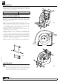
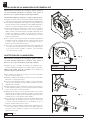
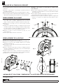
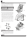
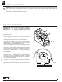
Settle the hose reel over a horizontal robust surface. There are two
different hose outlet positions available. To be able to change the hose
outlet position, it is necessary:
1. Make sure the hose reel is firmly fixed over a horizontal surface.
2. The spool must be blocked by means of the ratchet, to avoid the
power springs to turn it. To block the spool, extract the hose to the
nearest blocking ratchet position. During the hose outlet substitution
process, be careful not to let the spool turn freely.
3. Unscrew the bolts (1), take out the hose outlet rollers (2) , and
disassemble the crosspiece (4) (Fig. 1).
4. Orientate the hose (it is not necessary to disassemble the hose
stopper) towards the new hose outlet position. To do this, grab firmly
the hose, unlatch the spool and turn it until the hose reach its new
position (Fig. 2). Then, latch the spool again, at the nearest position.
5. Assemble between then, the hose outlet components took apart
previously as shown (Fig. 3), and take them to their new position as
shown. Then, screw the bolts (3) (Fig. 4).
6. Finally, assemble the crosspiece (4) (Fig. 4) at the indicated position.
Fig. 1
Fig. 2
Fig. 3
Fig. 4
1
4
2
1
1
1
3
43
3
3
!

3
R. 02/22 850 829
SAMOA Industrial, S.A. · Pol. Ind. Porceyo, I-14 · Camino del Fontán, 831 · 33392 - Gijón - Spain · Tel.: +34 985 381 488 · www.samoaindustrial.com
2022_02_17-13:00
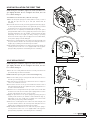
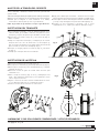
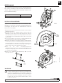
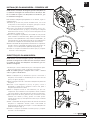
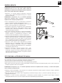
NOTE: During hose installation, tighten the U-bolt just till the hose
gets slightly deformed. Do not overtighten the U-bolt, since the
hose could be damaged.
To install the hose the first time, follow the next steps:
1. Make sure the power springs are relaxed, with no tension, in such a
way that the spool does not try to turn (the ratchet must be
unlocked).
2. Connect the new hose to the gooseneck (2), place the U-bolt (1) (Fig. 5)
in such a way that it firmly holds the hose against the spool, and start
to wind the hose into the spool turning the spool manually.
3. Once the hose is completely wound around the spool (the power
springs still will be with no tension), apply the pretension to the power
springs by turning the spool the number or turns stated in the table
depending on the hose length (see table), turning in positively
direction as shown in (Fig. 6). Do not apply more tension than stated,
as the power springs could be damaged.
4. Pass the hose end through the roller outlet to the desired length, lock
the spool with the ratchet in the nearest position and place the hose
stopper (Fig. 7) making sure the latch keeps accessible.
5. Fully unwind and rewind the hose to make sure the power springs are
correctly tensioned. The hose reel is equipped with 2 strong power
springs working in parallel to assist during the hose rewinding.
HOSE INSTALLATION THE FIRST TIME
Fig. 5
+-
Fig. 6
1
2
Fig. 7
HOSE REPLACEMENT
NOTE: During hose installation, tighten the U-bolt just till the hose
gets slightly deformed. Do not overtighten the U-bolt, since the
hose could be damaged.
1. Ensure the reel is firmly attached. Take the hose fully out and let the
spool blocked by the ratchet mechanism.
NOTE: beware the spool to get loose and start turning freely.
2. Remove the U-bolt (1) by loosening its nuts and disconnect the hose
from the gooseneck (2) (Fig. 5).
3. Take away the hose from the spool and remove the hose stopper in
order to use it with the new hose.
4. Connect the new hose to the gooseneck. Place the U-bolt in such a
way that it firmly holds the hose against the spool, and pull the hose
in order to unlock the ratchet.
5. Allow the hose to slowly wind into the spool and ensure to finish with
the whole hose inside the reel and the power springs with no tension
(in such a way that the spool does not try to turn).
6. Apply the pre-tension to the power springs by turning the spool
towards positive direction, the number of turns indicated in (Fig. 6),
depending on the hose length. Do not apply more tension than
stated, as the power spring could be damaged.
7. Pass the hose end through the roller outlet to the desired length, lock
the spool with the ratchet in the nearest position and place the hose
stopper (Fig. 7) making sure the latch keeps accessible.
8. Fully unwind and rewind the hose to make sure the power spring is
correctly tensioned. The hose reel is equipped with 2 strong power
springs working in parallel to assist during the hose rewinding.
HOSE LENGTH HOSE 1 1-2"
15 m (50') + 7 turns

4850 829 R. 02/22
SAMOA Industrial, S.A. · Pol. Ind. Porceyo, I-14 · Camino del Fontán, 831 · 33392 - Gijón - Spain · Tel.: +34 985 381 488 · www.samoaindustrial.com
2022_02_17-13:00
EN
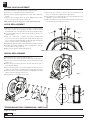
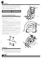
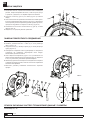
SWIVEL REPLACEMENT
If you wish to increase or decrease the power springs tension:
1. Pull the hose out till the first ratchet locking position.
2. Remove the hose stopper and pull the hose out in order to unlock the
ratchet.
3. Allow the hose to fully wind into the spool, applying some counter-
force in order to avoid the spool to turn freely.
NOTE: beware the spool may get loose and start turning freely.
SPRING LOAD ADJUSTMENT
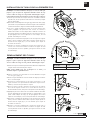
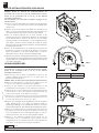
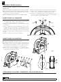
LATCH REPLACEMENT
1. With the hose fully wound on the spool and the hose stopper touching
the rollers, turn the spool enought to be able to reach the ratchet
assembly. Make sure to avoid the spool to turn freely, blocking it safely.
2. Loosen the 2 bolts (1) (Fig. 8), and the 4 nuts (2) (Fig. 8). Remove the
ratchet assembly.
3. Clean the components, or replace the ratchet assembly with
a new one. In the case of unscrewing the ratchet shaft (3) (Fig. 6), be
sure to clean the thread and apply medium-strength threadlocker
before screwing it back into the plate (4) (Fig. 6).
4. Assemble the ratchet assembly in place and tight the 2 bolts (1) (Fig. 6).
4. Assemble the ratchet assembly in place and tight the 2 bolts (1)
(Fig. 8), and the 4 nuts (2) (Fig. 8).
5. Make sure the ratchet assembly works properly.
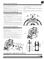
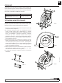
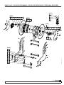
1. Disconnect the hose of the inlet shaft (1) (Fig. 9).
2. Loosen the set screw in the nut (2) and remove said nut (3) (Fig. 10).
3. Remove the screws (4) and the lateral cover (5) and the spacer tube
(6) (Fig. 10).
4. Remove the gooseneck from the swivel. Use two wrenches in order to
avoid any shaft damage.
5. Remove the swivel (7) (Fig. 10 & 11) and replace it with a new one, or
replace the seals (8) (Fig. 11). Make sure the seals are placed correctly.
6. Grease the interior of the swivel and place it carefully back on the shaft
until it touches the bearing on the spool.
7. Place back the rest of parts in reverse order. Fig. 9
Fig. 11
Fig. 10
1
1
3
7
762
5
8
8
TROUBLESHOOTING / DIMENSIONS / PARTS LIST
Pages: 21 and 22.
4
4. Turn the spool to increase or decrease the power springs tension.
Never exceed the turns indicated in the table (Fig. 6).
5. Pass again the hose end through the roller outlet and place the hose
stopper (Fig. 7) at the desired position.
6. Make sure that the hose fully winds and unwinds properly. If it does
not, repeat the previous steps until it does.
Fig. 8
1
2
1
2
4
3

5
R. 02/22 850 829
SAMOA Industrial, S.A. · Pol. Ind. Porceyo, I-14 · Camino del Fontán, 831 · 33392 - Gijón - Spain · Tel.: +34 985 381 488 · www.samoaindustrial.com
2022_02_17-13:00
ES
INSTALACIÓN-MODO DE EMPLEO
Enrollador de manguera abierto de construcción muy robusta para
aplicaciones de gran caudal o de gran capacidad de manguera.
Recogida de manguera asistida por medio de un par de resortes.
Estructura de acero con acabado en resina poliéster. Especialmente
indicado para trabajos pesados.
DESCRIPCIÓN
ATENCIÓN: Antes de empezar cualquier tipo de mantenimiento,
cierre la válvula más cercana al enrollador y abra la válvula de
salida para soltar la presión en la manguera. El resorte esta bajo
muy alta tensión y puede producir graves heridas si se suelta. Por
lo tanto, no intente dar servicio al resorte dentro del enrollador.
MANTENIMIENTO
FLUIDOS CAPACIDADES DE MANGUERA
Agua, gasóleo, aspiración, Adblue®1-1/2" 15 m (50')
Fig. 1
Fig. 2
Fig. 3 Fig. 4
1
4
2
1
1
1
3
43
3
3
!
Asiente el enrollador sobre una superficie horizontal robusta y
resistente. Existen dos posibles posiciones de salida de manguera.
Para intercambiar la posición de salida de manguera, será necesario:
1. Que se asegure de que el enrollador está firmemente sujeto sobre una
superficie horizontal.
2. El tambor del enrollador debe estar bloqueado por el trinquete, para
que no tienda a girar por la acción de los resortes. Para ello, extraiga
ligeramente la manguera hasta su primera posición de trincado.
Durante el proceso de sustitución de la posición de la salida de
manguera, tenga cuidado de no dejar girar el tambor libremente.
3. Desmonte los tornillos (1) y extraiga los rodillos de salida de manguera
(2) y desmonte el travesaño (4) (Fig. 1).
4. Oriente la manguera (no es necesario que desmonte el tope de
manguera) hacia la nueva posición de la salida, para ello, sujete
firmemente la manguera, libere el tambor del trinquete, y gírelo hasta
que la manguera apunte hacia su nueva posición de salida (Fig. 2).
Bloquee el tambor de nuevo en la posición de trincado más próxima.
5. Ensamble entre sí los componentes de la salida de manguera
desmontados previamente según (Fig. 3), y llevelos a su nueva
posición según, apretando los tornillos (3) (Fig. 4).
6. Finalmente ensamble el travesaño (4) (Fig. 4) en la posición indicada.

6850 829 R. 02/22
SAMOA Industrial, S.A. · Pol. Ind. Porceyo, I-14 · Camino del Fontán, 831 · 33392 - Gijón - Spain · Tel.: +34 985 381 488 · www.samoaindustrial.com
2022_02_17-13:00
ES
NOTA: Durante la instalación de la manguera, apriete el abarcón
sólo hasta deformar ligeramente la manguera. Evite apretar el
abarcón en exceso pues la manguera puede llegar a dañarse.
Para instalar la manguera por primera vez, seguir los siguientes pasos:
1. Asegúrese de que los resortes no tienen tensión dejando el tambor neutro,
de modo que no intente girar mas (el trinquete debe estar desbloqueado).
2. Conecte la nueva manguera al cuello de ganso (2) coloque el abarcón (1)
(Fig. 5) de modo que sujete a la manguera contra el tambor firmemente y
comience a recoger la manguera girando el tambor manualmente.
3. Una vez la manguera esté totalmente recogida (los resortes deberán
seguir neutros), aplique la pre-tensión a los resortes, girando el
tambor el número de vueltas indicado en la tabla dependiendo de la
longitud de la manguera (ver tabla), en sentido positivo según (Fig.
6). No se debe aplicar más tensión de la indicada, pues los resortes
podrían resultar dañados.
4. Pase el extremo de la manguera a través de la salida de manguera la
longitud deseada, deje el tambor trincado en la posición más cercana
y coloque el tope de manguera (Fig. 7) asegurándose de que el
trinquete quede accesible desde el exterior.
5. Desenrolle y enrolle la manguera totalmente para comprobar que
los resortes están tensados de forma correcta. El enrollador dispone
de dos fuertes resortes montados en paralelo, estos funcionarán
como asistencia a la recogida.
INSTALACIÓN DE LA MANGUERA POR PRIMERA VEZ
Fig. 5
+-
Fig. 6
1
2
Fig. 7
SUSTITUCION DE LA MANGUERA
NOTA: Durante la instalación de la manguera, apriete el abarcón
sólo hasta deformar ligeramente la manguera. Evite apretar el
abarcón en exceso pues la manguera puede llegar a dañarse.
1. Asegúrese de que el enrollador de manguera este firmemente sujeto.
Desenrolle totalmente la manguera y deje el tambor fijado por el trinquete.
NOTA: Tenga cuidado para que el trinquete no se suelte y el
enrollador empiece a girar libremente.
2. Retire el abarcón (1) aflojando sus tuercas y desconecte la manguera
del cuello de ganso (2) (Fig. 5).
3. Extraiga la manguera del tambor y desmonte el tope de manguera
para usarlo con la manguera nueva.
4. Conecte la nueva manguera al cuello de ganso, coloque el abarcón de
modo que sujete la manguera contra el tambor firmemente, y tire de
ella para soltar el trinquete.
5. Deje la manguera recogerse lentamente y asegúrese de terminar con
toda la longitud enrollada y los resortes sin tensión (dejando el tambor
neutro, de modo que no intente girar más).
6. Aplique la pre-tensión a los resortes, girando el tambor el nº de vueltas
dependiendo de la longitud de manguera, girando en sentido positivo
según se muestra en la (Fig. 6). No se debe aplicar más tensión de la
indicada, pues los resortes pueden resultar dañados.
7. Pase el extremo de la manguera a través de la salida de manguera la
longitud deseada, deje el tambor trincado en la posición más cercana
y coloque el tope de manguera (Fig. 7) asegurándose de que el
trinquete quede accesible desde el exterior.
8. Desenrolle y enrolle la manguera totalmente para comprobar que los
resortes están tensados de forma correcta. El enrollador dispone de
dos fuertes resortes montados en paralelo, estos funcionarán como
asistencia a la recogida.
LONGITUD DE
MANGUERA MANGUERA
1 1-2"
15 m Pretensión = 7 vueltas

7
R. 02/22 850 829
SAMOA Industrial, S.A. · Pol. Ind. Porceyo, I-14 · Camino del Fontán, 831 · 33392 - Gijón - Spain · Tel.: +34 985 381 488 · www.samoaindustrial.com
2022_02_17-13:00
ES
SUSTITUCIÓN DE LA RÓTULA
AJUSTE DE LA TENSIÓN DEL RESORTE
SUSTITUCIÓN DEL TRINQUETE
1. Con la manguera enrollada y el tope de manguera apoyado en los
rodillos de salida, gire el tambor lo suficiente como para tener acceso
al trinquete, y asegúrese de impedir el giro del tambor de forma segura.
2. Desenrosque los 2 tornillos (1) (Fig. 8)–, y las 4 tuercas (2) (Fig. 8).
Retire el conjunto.
3. Limpie los componentes del trinquete, o sustitúyalo por un conjunto
trinquete nuevo. En el caso de desenroscar el eje del trinquete (3)
(Fig. 6), asegúrese de limpiar la rosca y aplicar fijador de fuerza media
previo a roscarlo de nuevo sobre la chapa (4) (Fig. 6).
4. Colóquelo en su lugar y apriete los tornillos (1) (Fig. 8), y las tuercas
(2) (Fig. 8).
5. Verifique que el trinquete funciona correctamente.
1. Desconecte la manguera de acometida (1) (Fig. 9).
2. Afloje el prisionero de la tuerca (2) y desenrosque dicha tuerca (3) (Fig. 10).
3. Desenrosque los tornillos (4) y retire la chapa lateral (5) y el casquillo
separador (6) (Fig. 10).
4. Desconecte el cuello de ganso de la rótula. Utilice dos llaves para
evitar dañar el eje.
5. Retire el cuerpo de rótula (7) (Fig. 10 & 11) y sustitúyala por una
nueva o bien sustituya las juntas (8) (Fig. 11) asegurándose de que
estén en la posición correcta.
6. Engrase el interior de la rótula e insértela cuidadosamente de nuevo
en el eje hasta que haga tope con el rodamiento del disco.
7. Vuelva a colocar el resto de elementos en orden inverso.
Fig. 9
Fig. 11
Fig. 10
1
7
1
3
7
4
62
5
8
8
Si desea aumentar o disminuir la tensión del resorte, proceda de la
siguiente forma:
1. Desenrolle la manguera hasta llegar a la primera posición de bloqueo del trinquete.
2. Quite el tope de manguera y tire de la manguera para soltar el trinquete.
3. Permita que la manguera se enrolle totalmente en el tambor,
reteniéndola lo suficiente para que éste no gire libremente.
NOTA: Tenga cuidado de que la bobina no empiece a girar libremente.
ANOMALÍAS Y SUS SOLUCIONES / DIMENSIONES / LISTA DE RECAMBIOS
Ver páginas: 21 y 22.
4. Haga girar la bobina para incrementar o disminuir la tensión según.
Nunca sobrepase las vueltas de pretensión indicadas en la tabla (Fig. 6).
5. Vuelva a pasar el extremo de la manguera a través de la salida de rodillos
y coloque el tope de manguera en la posición deseada según (Fig. 7).
6. Asegúrese de que la manguera se desenrolla y que se recoge
completamente. Si no, repita el procedimiento hasta que lo haga.
Fig. 8
1
2
1
2
4
3

8850 829 R. 02/22
SAMOA Industrial, S.A. · Pol. Ind. Porceyo, I-14 · Camino del Fontán, 831 · 33392 - Gijón - Spain · Tel.: +34 985 381 488 · www.samoaindustrial.com
2022_02_17-13:00
FR
INSTALLATION-MODE D’EMPLOI
Enrouleur de tuyau ouvert de construction très robuste pour les
applications à haut débit ou à grande capacité de tuyau. Enroulement
de tuyau assisté par ressort au moyen d’une paire de ressorts.
Construction en acier avec finition en résine de polyester.
Particulièrement adapté aux applications lourdes.
DESCRIPTION
ATTENTION: Avant de commencer tout entretien, fermez la
vanne la plus proche de l’enrouleur et ouvrez la vanne de sortie
pour libérer la pression dans le tuyau. Le ressort est sous très haute
tension et peut causer des blessures graves s’il est relâché. Par
conséquent, n’essayez pas de réparer le ressort à l’intérieur
de l’enrouleur.
ENTRETIEN
FLUIDES CAPACITÉS DU FLEXIBLE
Eau, diesel, aspiration, Adblue® 1-1/2" 15 m (50')
Fig. 1
Fig. 2
Fig. 3 Fig. 4
1
4
2
1
1
1
3
43
3
3
!
Placez le dévidoir sur une surface solide et horizontale. Il y a deux
positions possibles pour la sortie du tuyau. Il sera nécessaire de
modifier la position de la sortie du tuyau:
1. Assurez-vous que l’enrouleur est fermement fixé sur une
surface horizontale.
2. Le tambour de l’enrouleur doit être bloqué par le cliquet afin qu’il
n’ait pas tendance à tourner sous l’effet du ressort. Pour ce faire, tirez
légèrement le tuyau jusqu’à sa première position d’arrimage. Pendant
le processus de changement de la position de la sortie du tuyau,
veillez à ne pas laisser le tambour tourner librement.
3. Enlevez les vis (1) et retirez les rouleaux de sortie du tuyau (2) et
retirez la barre transversale (4) (Fig. 1).
4. Orientez le tuyau (il n’est pas nécessaire de retirer la butée du tuyau)
vers la nouvelle position de sortie en tenant fermement le tuyau, en
relâchant le tambour du cliquet et en le tournant jusqu’à ce que le
tuyau pointe vers sa nouvelle position de sortie (Fig. 2). Verrouillez le
tambour dans la position de cliquet la plus proche.
5. Assemblez les composants de la sortie du tuyau démontés
précédemment (Fig. 3) et mettez-les dans leur nouvelle position en
serrant les vis (3) (Fig. 4).
6. Enfin, montez la traverse (4) (Fig. 4) dans la position indiquée.

9
R. 02/22 850 829
SAMOA Industrial, S.A. · Pol. Ind. Porceyo, I-14 · Camino del Fontán, 831 · 33392 - Gijón - Spain · Tel.: +34 985 381 488 · www.samoaindustrial.com
2022_02_17-13:00
FR
REMARQUE : Pendant l’installation du tuyau, ne serrez le collier que
jusqu’à ce que le tuyau soit légèrement déformé. Évitez de trop
serrer le collier de serrage car cela pourrait endommager le tuyau.
Pour installer le tuyau pour la première fois, suivez les étapes ci-dessous:
1. S’assurer que les ressorts ne sont pas sous tension en laissant le tambour
au point mort, de sorte qu’aucune autre rotation ne soit tentée (le cliquet
doit être déverrouillé).
2. Raccordez le nouveau tuyau au col de cygne (2), positionnez le collier (1) (Fig.
5) de manière à ce qu’il maintienne fermement le tuyau contre le tambour et
commencez à ramasser le tuyau en tournant le tambour manuellement.
3. Une fois le tuyau complètement rentré (les ressorts doivent rester
neutres), appliquer une pré-tension aux ressorts en tournant le
tambour du nombre de tours indiqué dans le tableau en fonction de
la longueur du tuyau (voir tableau), dans un sens positif selon (Fig. 6).
Ne pas appliquer une tension supérieure à celle indiquée, car cela
pourrait endommager les ressorts.
4. Faites passer l’extrémité du tuyau par la sortie de tuyau à la longueur
désirée, laissez le tambour arrimé dans la position la plus proche et
montez l’arrêt de tuyau (Fig. 7) en vous assurant que le cliquet est
accessible de l’extérieur.
5. Déroulez et enroulez complètement le tuyau pour vérifier que les
ressorts sont correctement tendus. L’enrouleur est équipé de deux
ressorts puissants montés en parallèle, qui agissent comme une aide
au rembobinage.
INSTALLATION DU TUYAU POUR LA PREMIÈRE FOIS
Fig. 5
+-
Fig. 6
1
2
Fig. 7
REMPLACEMENT DES TUYAUX
REMARQUE : Pendant l’installation du tuyau, ne serrez le collier que
jusqu’à ce que le tuyau soit légèrement déformé. Évitez de trop
serrer le collier de serrage car cela pourrait endommager le tuyau.
1. Assurez-vous que l’enrouleur de tuyau est bien fixé. Déroulez complètement
le tuyau et laissez l’enrouleur fixé par le cliquet.
NOTA: Tenga cuidado para que el trinquete no se suelte y el
enrollador empiece a girar libremente.
2.Retirez le couvercle (1) en desserrant ses écrous et débranchez le tuyau
à col de cygne (2) (Fig. 5).
3. Retirez le tuyau du tambour et retirez la butée du tuyau pour l’utiliser
avec le nouveau tuyau.
4. Connectez le nouveau tuyau au col de cygne, positionnez le col de
cygne de manière à ce qu’il maintienne fermement le tuyau contre le
tambour, et tirez dessus pour libérer le cliquet.
5. Laissez le tuyau se rétracter lentement et assurez-vous de terminer
avec toute la longueur enroulée et les ressorts libres de tension (en
laissant le tambour neutre, afin qu’il n’essaie pas de tourner davantage).
6. Appliquer la pré-tension aux ressorts en tournant le tambour du nombre
de tours dépendant de la longueur du tuyau, en tournant dans le sens
positif comme indiqué sur la (Fig. 6). Ne pas appliquer une tension
supérieure à celle indiquée, car les ressorts pourraient être endommagés.
7. Faites passer l’extrémité du tuyau par la sortie de tuyau à la longueur
désirée, laissez le tambour arrimé dans la position la plus proche et
montez l’arrêt de tuyau (Fig. 7) en vous assurant que le cliquet est
accessible de l’extérieur.
8. Déroulez et enroulez complètement le tuyau pour vérifier que les
ressorts sont correctement tendus. L’enrouleur est équipé de deux
ressorts puissants montés en parallèle, qui agissent comme une aide
au rembobinage.
LONGUEUR
DU TUYAU TUYAU
1 1-2"
15 m Prétension = 7 tours

10 850 829 R. 02/22
SAMOA Industrial, S.A. · Pol. Ind. Porceyo, I-14 · Camino del Fontán, 831 · 33392 - Gijón - Spain · Tel.: +34 985 381 488 · www.samoaindustrial.com
2022_02_17-13:00
FR
REMPLACEMENT DE LA ROTULE
RÉGLAGE DE LA TENSION DU RESSORT
REMPLACEMENT DU CLIQUET
1. Avec le tuyau enroulé et la butée de tuyau reposant sur les rouleaux de
sortie, faites tourner le tambour suffisamment pour avoir accès au
cliquet, et veillez à empêcher le tambour de tourner de manière sûre.
2. Dévissez les 2 vis (1) (Fig. 8) et les 4 écrous (2) (Fig. 8). Retirer
l’assemblage.
3. Nettoyez les composants du cliquet, ou remplacez-le par un nouvel
ensemble de cliquet. En cas de dévissage de l’arbre à cliquet (3) (Fig.
6), veillez à nettoyer le filetage et à appliquer un frein filet de force
moyenne avant de le revisser dans la plaque (4) (Fig. 6).
4. Mettez-le en place et serrez les boulons (1) (Fig. 8), et les
écrous (2) (Fig. 8).
5. Vérifiez que le cliquet fonctionne correctement.
1. Débranchez le tuyau d’alimentation (1) (Fig. 9).
2. Desserrez la vis de réglage de l’écrou (2) et dévissez l’écrou (3) (Fig. 10).
3. Dévissez les vis (4) et retirez la plaque latérale (5) et la douille
d’écartement (6) (Fig. 10).
4. Déconnectez le col de cygne de la rotule. Utilisez deux clés pour éviter
d’endommager l’axe.
5. Retirez le corps de la rotule (7) (Fig. 10 & 11) et remplacez-le par un
nouveau ou remplacez les joints (8) (Fig. 11) en vous assurant qu’ils
sont dans la bonne position.
6. Graissez l’intérieur de la rotule et réinsérez-la avec précaution sur
l’arbre jusqu’à ce qu’elle vienne buter contre le roulement du disque.
7. Remplacez le reste des éléments dans l’ordre inverse.
Fig. 9
Fig. 11
Fig. 10
1
7
1
3
7
4
62
5
8
8
Si vous souhaitez augmenter ou diminuer la tension du ressort, procédez
comme suit:
1. Déroulez le tuyau jusqu’à ce qu’il atteigne la première position de
verrouillage du cliquet.
2. Retirez le bouchon du tuyau et tirez sur le tuyau pour libérer le cliquet.
3. Laissez le tuyau s’enrouler complètement autour du tambour, en le retenant
suffisamment longtemps pour que le tambour ne tourne pas librement.
ANOMALIES ET SOLUTIONS / DIMENSIONS / LA LISTE DES PIÈCES DE RECHANGE
Voir pages: 21 et 22.
REMARQUE : Faites attention à ce que la bobine ne commence pas à
tourner librement.
4. Faites tourner la bobine pour augmenter ou diminuer la tension en
conséquence. Ne jamais dépasser les tours de précontrainte indiqués
dans le tableau (Fig. 6).
5. Faites repasser l’extrémité du tuyau par la sortie du rouleau et placez la
butée du tuyau dans la position souhaitée selon (Fig. 7).
6. Assurez-vous que le tuyau est déroulé et qu’il est complètement
rétracté. Si ce n’est pas le cas, répétez la procédure jusqu’à ce que ce
soit le cas.
Fig. 8
1
2
1
2
4
3

11
R. 02/22 850 829
SAMOA Industrial, S.A. · Pol. Ind. Porceyo, I-14 · Camino del Fontán, 831 · 33392 - Gijón - Spain · Tel.: +34 985 381 488 · www.samoaindustrial.com
2022_02_17-13:00
DE
INSTALLATION-BETRIEB
Extrem robust hohe Förderleistung und hohe Schlauchkapazität. Ein
Paar robuster, zuverlässiger Federn unterstützt das Aufrollen des
Schlauchs. Robuste Schlauchtrommel. Alle Metallkonstruktionen mit
Polyester-Pulverbeschichtung.
BEZEICHNUNG
WARNUNG: Bevor Sie Wartungsarbeiten durchführen, schließen
Sie das der Schlauchtrommel am nächsten gelegene Absperrventil
und öffnen Sie das Abgabeventil, um den Druck im Schlauch zu
entlasten. Die Aufrollfeder steht unter sehr hoher Spannung und
kann beim Lösen schwere Verletzungen verursachen. Versuchen
Sie daher nicht, die Feder in der Rolle zu warten.valve to relieve
the pressure in the hose.
WARTUNG
FLÜSSIGKEITEN SCHLAUCHKAPAZITÄT
Wasser, Dieselkraftstoff, Absaugung, DEF. 1-1/2" 15 m (50')
Abb. 1
Abb. 2
Abb. 3
Abb. 4
1
4
2
1
1
1
3
43
3
3
!
Legen Sie den Schlauchaufroller über eine horizontale, stabile
Oberfläche. Es stehen zwei verschiedene Schlauchauslasspositionen
zur Verfügung. Um die Position des Schlauchauslasses ändern zu
können, ist dies erforderlich:
1. Stellen Sie sicher, dass die Schlauchtrommel fest über einer horizontalen
Oberfläche befestigt ist.
2. Die Spule muss mit der Sperrklinke blockiert werden, damit die
Kraftfedern sie nicht drehen. Um die Spule zu blockieren, ziehen Sie
den Schlauch bis zur nächsten Position der Sperrklinke heraus. Achten
Sie beim Ersetzen des Schlauchauslasses darauf, dass sich die Spule
nicht frei dreht.
3. Lösen Sie die Schrauben (1), nehmen Sie die Schlauchauslassrollen (2)
heraus und demontieren Sie das Querstück (4) (Abb. 1).
4. Richten Sie den Schlauch (es ist nicht erforderlich, den Schlauchstopper
zu demontieren) auf die neue Schlauchauslassposition aus. Greifen Sie
dazu den Schlauch fest, entriegeln Sie die Spule und drehen Sie sie,
bis der Schlauch seine neue Position erreicht (Abb. 2). Verriegeln Sie
dann die Spule wieder an der nächstgelegenen Position.
5. Bauen Sie die zuvor auseinandergenommenen
Schlauchauslasskomponenten wie gezeigt zusammen (Abb. 3) und
bringen Sie sie wie gezeigt an ihre neue Position. Schrauben Sie dann
die Schrauben (3) fest (Abb. 4).
6. Montieren Sie abschließend das Querstück (4) (Abb. 4) an der
angezeigten Position.

12 850 829 R. 02/22
SAMOA Industrial, S.A. · Pol. Ind. Porceyo, I-14 · Camino del Fontán, 831 · 33392 - Gijón - Spain · Tel.: +34 985 381 488 · www.samoaindustrial.com
2022_02_17-13:00
DE
HINWEIS: Ziehen Sie während der Schlauchinstallation die
U-Schraube nur so weit an, bis sich der Schlauch leicht verformt.
Ziehen Sie die U-Schraube nicht zu fest an, da der Schlauch
beschädigt werden könnte.
Um den Schlauch zum ersten Mal zu installieren, befolgen Sie die
nächsten Schritte:
1. Stellen Sie sicher, dass die Antriebsfedern entspannt sind, ohne Spannung,
so dass die Spule nicht versucht, sich zu drehen (die Sperrklinke muss
entriegelt sein).
2. Schließen Sie den neuen Schlauch (2) an, platzieren Sie den U-Bolzen (1)
(Abb. 5) so, dass er den Schlauch fest an der Spule hält, und beginnen Sie,
den Schlauch drehend auf die Spule zu wickeln die Spule manuell.
3. Wenn der Schlauch vollständig um die Spule gewickelt ist (die
Antriebsfedern sind noch ohne Spannung), bringen Sie die Vorspannung
auf die Antriebsfedern auf, indem Sie die Spule um die in der Tabelle
angegebene Anzahl von Umdrehungen je nach Schlauchlänge drehen
(siehe Tabelle ), drehen in positiver Richtung wie in (Abb. 6) gezeigt.
Wenden Sie nicht mehr Spannung als angegeben an, da die Antriebsfedern
beschädigt werden könnten.
4. Führen Sie das Schlauchende bis zur gewünschten Länge durch den
Rollenauslass, verriegeln Sie die Spule mit der Ratsche in der nächsten
Position und platzieren Sie den Schlauchstopper (Abb. 7), wobei Sie
darauf achten müssen, dass die Verriegelung zugänglich bleibt.
5. Wickeln Sie den Schlauch vollständig ab und wieder auf, um sicherzustellen,
dass die Antriebsfedern richtig gespannt sind. Der Schlauchaufroller ist mit
2 parallel arbeitenden, starken Druckfedern ausgestattet, die das Aufrollen
des Schlauchs unterstützen.
ERSTE INSTALLATION DES SCHLAUCHS
Abb. 5
+-
Abb. 6
1
2
Abb. 7
SCHLAUCHWECHSEL
HINWEIS: Ziehen Sie während der Schlauchinstallation die
U-Schraube nur so weit an, bis sich der Schlauch leicht verformt.
Ziehen Sie die U-Schraube nicht zu fest an, da der Schlauch
beschädigt werden könnte.
1. Stellen Sie sicher, dass die Spule fest angebracht ist. Ziehen Sie den
Schlauch vollständig heraus und lassen Sie die Spule durch den
Ratschenmechanismus blockieren.
HINWEIS: Achten Sie darauf, dass sich die Spule löst und sich frei dreht.
2. Entfernen Sie den U-Bolzen (1), indem Sie seine Muttern lösen, und
trennen Sie den Schlauch vom Schwanenhals (2) (Abb. 5).
3. Nehmen Sie den Schlauch von der Spule und entfernen Sie den
Schlauchstopper, um ihn mit dem neuen Schlauch zu verwenden.
4. Verbinden Sie den neuen Schlauch mit dem Schwanenhals. Platzieren
Sie den U-Bolzen so, dass er den Schlauch fest an der Spule hält, und
ziehen Sie am Schlauch, um die Ratsche zu entriegeln.
5. Allow the hose to slowly wind into the spool and ensure to finish with
the whole hose inside the reel and the power springs with no tension
(in such a way that the spool does not try to turn).
6. Bringen Sie die Vorspannung auf die Antriebsfedern, indem Sie die Spule in
positive Richtung drehen, die in (Abb. 6) angegebene Anzahl von
Umdrehungen, abhängig von der Schlauchlänge. Wenden Sie nicht mehr
Spannung als angegeben an, da die Antriebsfeder beschädigt werden könnte.
7. Führen Sie das Schlauchende bis zur gewünschten Länge durch den
Rollenauslass, verriegeln Sie die Spule mit der Ratsche in der nächsten
Position und platzieren Sie den Schlauchstopper (Abb. 7), wobei Sie
darauf achten müssen, dass die Verriegelung zugänglich bleibt.
8. Wickeln Sie den Schlauch vollständig ab und wieder auf, um
sicherzustellen, dass die Antriebsfeder richtig gespannt ist. Der
Schlauchaufroller ist mit 2 parallel arbeitenden, starken Druckfedern
ausgestattet, die das Aufrollen des Schlauchs unterstützen.
SCHLAUCHLÄNGE SCHLAUCH 1 1-2”
15 m (50') + 7 Umdrehungen

13
R. 02/22 850 829
SAMOA Industrial, S.A. · Pol. Ind. Porceyo, I-14 · Camino del Fontán, 831 · 33392 - Gijón - Spain · Tel.: +34 985 381 488 · www.samoaindustrial.com
2022_02_17-13:00
DE
AUSTAUSCH DES SCHWENKERS
EINSTELLUNG DER FEDERLAST
AUSTAUSCH DER VERRIEGELUNG
1. Wenn der Schlauch vollständig auf die Spule gewickelt ist und der
Schlauchstopper die Rollen berührt, drehen Sie die Spule so weit, dass
Sie die Ratschenbaugruppe erreichen können. Achten Sie darauf, dass
sich die Spule nicht frei dreht und blockiert sie sicher.
2. Lösen Sie die 2 Schrauben (1) (Abb. 8) und die 4 Muttern (2) (Abb. 8).
Entfernen Sie die Ratscheneinheit.
3. Reinigen Sie die Komponenten oder ersetzen Sie die Ratscheneinheit
durch eine neue. Beim Abschrauben des Ratschenschaftes (3) (Abb. 6)
unbedingt das Gewinde reinigen und mittelfesten
Schraubensicherungslack auftragen, bevor er wieder in die Platte (4)
eingeschraubt wird (Abb. 6).
4. Montieren Sie die Ratschenbaugruppe und ziehen Sie die 2 Schrauben
(1) fest (Abb. 6). 4. Montieren Sie die Ratschenbaugruppe und ziehen
Sie die 2 Schrauben (1) (Abb. 8) und die 4 Muttern (2) (Abb. 8) fest.
5. Stellen Sie sicher, dass die Ratscheneinheit ordnungsgemäß funktioniert.
1. Trennen Sie den Schlauch des Einlassschachts (1) (Abb. 9).
2. Lösen Sie den Gewindestift in der Mutter (2) und entfernen Sie die
Mutter (3) (Abb. 10).
3. Entfernen Sie die Schrauben (4) und die seitliche Abdeckung (5) und
das Distanzrohr (6) (Abb. 10).
4. Entfernen Sie den Schwanenhals vom Wirbel. Verwenden Sie zwei
Schlüssel, um Schäden an der Welle zu vermeiden.
5. Entfernen Sie das Drehgelenk (7) (Abb. 10 & 11) und ersetzen Sie es
durch ein neues oder ersetzen Sie die Dichtungen (8) (Abb. 11).
Stellen Sie sicher, dass die Dichtungen richtig platziert sind.
6. Schmieren Sie das Innere des Drehgelenks und setzen Sie es vorsichtig
wieder auf die Welle, bis es das Lager auf der Spule berührt.
7. Setzen Sie die restlichen Teile in umgekehrter Reihenfolge wieder ein.
Abb. 9
Abb. 11
Abb. 10
1
7
1
3
7
4
62
5
8
8
Wenn Sie die Spannung der Antriebsfedern erhöhen oder verringern möchten:
1. Ziehen Sie den Schlauch bis zur ersten Raststellung heraus.
2.Entfernen Sie den Schlauchstopper und ziehen Sie den Schlauch heraus, um die
Ratsche zu entriegeln.
3.Lassen Sie den Schlauch vollständig auf die Spule aufwickeln und wenden Sie etwas
Gegenkraft an, um zu verhindern, dass sich die Spule frei dreht.
HINWEIS: Achten Sie darauf, dass sich die Spule lösen und frei drehen kann.
FEHLERBEHEBUNG / ABMESSUNGEN / TEILELISTE
Seiten: 21 und 22.
4. Drehen Sie die Spule, um die Spannung der Antriebsfedern zu erhöhen
oder zu verringern. Niemals die in der Tabelle (Abb. 6) angegebenen
Umdrehungen überschreiten.
5. Führen Sie das Schlauchende erneut durch den Rollenausgang und
platzieren Sie den Schlauchstopper (Abb. 7) an der gewünschten
Position.
6. Stellen Sie sicher, dass sich der Schlauch vollständig auf- und abwickelt.
Wenn dies nicht der Fall ist, wiederholen Sie die vorherigen Schritte, bis
dies der Fall ist .
Abb. 8
1
2
1
2
4
3

14 850 829 R. 02/22
SAMOA Industrial, S.A. · Pol. Ind. Porceyo, I-14 · Camino del Fontán, 831 · 33392 - Gijón - Spain · Tel.: +34 985 381 488 · www.samoaindustrial.com
2022_02_17-13:00
PT
INSTALAÇÃO-OPERAÇÃO
Carretel aberto com retração automática para mangueira, com
construção muito robusta para trabalhos que exigem grandes
vazões de abastecimento ou mangueiras com grande capacidade. A
mangueira é enrolada na roda do carretel por duas molas. Estrutura
em aço com acabamento em resina de poliéster. Especialmente
desenvolvido para trabalhos pesado.
DESCRIÇÃO
ATENÇÃO: Antes de fazer qualquer tipo de manutenção, fechar
o registro da linha que estiver mais próxima do carretel e acionar
gatilho ou comando de óleo, usado para fazer o abastecimento
do fluido, para eliminar toda a pressão do fluido da mangueira.
As molas estão sempre em tensão muito baixa e pode provocar
graves acidentes se soltar. Portanto, não tentar manusear as
molas dentro do carretel.
MANUTENÇÃO
FLUIDOS CAPACIDADE DA MANGUEIRA
Água, Óleo diesel, óleo
lubrificante e Adblue®1-1/2" 15 m (50')
Fig. 1
Fig. 2
Fig. 3
Fig. 4
1
4
2
1
1
1
3
43
3
3
!
Fixar o carretel sobre uma superfície horizontal robusta e resistente.
Existem duas possíveis posições para a saída da mangueira (Fig. 2).
Para intercalar a posição da saída da mangueira, será necessário:
1. Que o carretel esteja preso firmemente a uma superfície horizontal.
2. A roda do carretel deverá estar bloqueada pelo trinquete, para que
o giratório não possa se movimentar. Para isto puxar a mangueira
para fora até a primeira posição de bloqueio (primeira parada do
trinquete). Tomar cuidado para que a roda não gire sozinha.
3. Retirar os parafusos (1) e extrair o conjunto dos rodilhos de saída
da mangueira (2) e desmontar as travessas da saída(4) (Fig. 1).
4. Orientar a mangueira (não é necessário desmontar a abraçadeira
de parada) assim que a nova posição de saída da mangueira
estiver pronta, segurar firmemente a mangueira, puxar para
liberar a roda da posição de bloqueio do trinquete e girar a roda
até a mangueira aponte para a nova posição de saída (Fig. 2).
Bloquear a roda novamente na primeira posição de bloqueio do
trinquete.
5. Montar em conjunto os componentes da saída da mangueira, que
foram desmontados anteriormente, apertando os parafusos (3)
(Fig. 4).
6. Finalmente montar as travessas da saída (4) (Fig. 4) na posição
indicada.

15
R. 02/22 850 829
SAMOA Industrial, S.A. · Pol. Ind. Porceyo, I-14 · Camino del Fontán, 831 · 33392 - Gijón - Spain · Tel.: +34 985 381 488 · www.samoaindustrial.com
2022_02_17-13:00
PT
NOTA: Durante a instalação da mangueira, apertar a abraçadeira em
U, ajustando na mangueira até verificar uma leve deformação. Não
há necessidade de apertar esta abraçadeira excessivamente, pois
isso danificará a mangueira.
Para instalar a mangueira pela primeira vez no carretel, seguir os
seguintes passos:
1. Certificar que as molas não possuem nenhuma tensão, com a roda
neutra, travar a roda no bloqueio do trinquete, para que a roda não
gire sozinha (o trinquete deve estar bloqueado).
2. Conectar a nova mangueira à entrada da mangueira - pescoço (2) ,
colocar a abraçadeira em U (1) (Fig. 5), de forma que a mangueira
mantenha-se firme na roda, e começar a enrolar a mangueira na roda
manualmente, girando a roda.
3. Uma vez a mangueira completamente acomodada na roda (as molas
ainda continuam sem nenhuma tensão). Aplicar a pré-tensão as molas
girando a roda na quantidade de voltas, indicado na tabela abaixo, em
sentido positivo (Fig. 6). Não aplicar mais tensão do que a indicada neste
manual. O não cumprimento desta diretriz poderá causar acidentes.
4. Passar a extremidade da mangueira através das travessas no comprimento
desejado, deixar a roda travada na primeira posição de bloqueio do
trinquete e colocar a abraçadeira de parada da mangueira (Fig. 7).
5. Verificar se o trinquete esta travando em todas as posições, enquanto
desenrola e enrola a mangueira.
INSTALAÇÃO DA MANGUEIRA – PRIMEIRA VEZ
Fig. 5
+-
Fig. 6
1
2
Fig. 7
SUBSTITUIÇÃO DA MANGUEIRA
NOTA: Durante a troca da mangueira, apertar a abraçadeira em U,
ajustando na mangueira até verificar uma leve deformação. Não há
necessidade de apertar esta abraçadeira excessivamente, pois isso
danificará a mangueira.
1. Certificar que o carretel está firmemente preso a uma superfície plana.
Desenrolar a mangueira e travar a roda através do trinquete.
NOTA: Ter cuidado para que o trinquete não se solte e o carretel
comece a girar a roda livremente.
2. Retirar a abraçadeira U (1) afrouxando as porcas e desconectar a
mangueira, desconectando a extremidade presa no interior da roda
(pescoço de ganso) (2) (Fig. 5).
3. Extrair a mangueira da roda e desmontar a abraçadeira de parada da
mangueira.
4. Conectar a nova mangueira no pescoço de ganso, colocar a
abraçadeira U, fixando bem a mangueira contra a roda, puxar a
mangueira para destravar a catraca.
5. Deixar a mangueira enrolar na roda lentamente, ate que todo
comprimento esteja instalado na roda enquanto as molas continuam
sem tensão (deixar a roda neutra para que ela não possa girar mais).
6. Aplicar a pré-tensão nas molas, girando a roda, com numero de voltas
indicadas neste manual (7 voltas), girando em sentido positivo
segundo mostra a (Fig. 6). Não aplicar mais voltas do que a indicada
neste paragrafo.
7. Passar a extremidade da mangueira através das travessas da saída da
mangueira no comprimento desejado, deixar a roda travada na
primeira posição de bloqueio do trinquete e colocar a abraçadeira de
parada da mangueira (Fig. 7).
8. Verificar se o trinquete esta travando em todas as posições, enquanto
desenrola e enrola a mangueira.
COMPRIMENTO DA
MANGUEIRA MANGUEIRA
1 1-2"
15 m Numero de voltas =
7 voltas

16 850 829 R. 02/22
SAMOA Industrial, S.A. · Pol. Ind. Porceyo, I-14 · Camino del Fontán, 831 · 33392 - Gijón - Spain · Tel.: +34 985 381 488 · www.samoaindustrial.com
2022_02_17-13:00
PT
SUBSTITUIÇÃO DO GIRATÓRIO
AJUSTAR A TENSÃO DA MOLA
SUBSTITUIÇÃO DO TRINQUETE
1. Com a mangueira enrolada e a mangueira parada a descansar sobre os
rolos de saída, rodar o tambor o suficiente para ter acesso à catraca, e
ter a certeza de parar o tambor de girar com segurança.
2. Desaperte os 2 parafusos (1) (Fig. 8)-, e as 4 porcas (2) (Fig. 8). Retirar
a montagem.
3. Limpar os componentes da catraca, ou substituir por um novo conjunto
de catraca. No caso de desenroscar o eixo da catraca (3) (Fig. 6),
certifique-se de limpar a rosca e aplicar um bloqueador de rosca de
média resistência antes de a aparafusar novamente na placa (4) (Fig. 6).
4. Colocá-lo no lugar e apertar os parafusos (1) (Fig. 8), e as porcas (2)
(Fig. 8).
5. Verificar se a catraca está a funcionar correctamente.
1. Desconectar a mangueira de sucção presa ao giratório (1) (Fig. 9).
2. Afrouxar a porca de aperto (2) e remover a porca.
3. Desrosquear os parafusos (4) e retirar a lateral do carretel (5) (Fig. 10).
4. Desconectar o pescoço de ganso do giratório. Utilizar duas chaves
para não danificar o eixo. Lubrificar o interior do giratório e inserir de
novo o giratório no eixo até que alcance o rolamento da roda.
5. Retirar o corpo do giratório (7) (Figura 10 e 11) e substituir o giratório
por um novo, ou somente substituir as vedações (8) (Fig. 11),
colocando as peças nas posições corretas.
Fig. 9
Fig. 11
Fig. 10
1
7
1
3
7
4
62
5
8
8
Se desejar aumentar ou diminuir a tensão da mola, proceda da
seguinte forma:
1. Desenrolar a mangueira até chegar à primeira posição de bloqueio do trinquete.
2. Retirar a abraçadeira de parada e tirar a mangueira para soltar o trinquete.
3. Permitir que a mangueira enrolar totalmente na roda, tensionar o
suficiente para que a roda gire livremente.
NOTA: Ter cuidado para que roda não comece a girar sozinha.
PROBLEMAS E SOLUÇÕES / DIMENSÕES / PEÇAS DE REPOSIÇAO
Páginas: 21 e 22.
4. Fazer a roda girar para aumentar ou diminuir a tensão da mola (Fig. 7).
5. Voltar a passar a extremidade da mangueira através da saída dos
rodilhos e colocar a abraçadeira de parada na posição desejada.
6. Assegurar que a mangueira desenrola e enrola completamente. Se isto
não ocorrer, repetir os procedimentos acima até que a mangueira
comece a enrolar e desenrolar completamente.
Fig. 8
1
2
1
2
4
3

17
R. 02/22 850 829
SAMOA Industrial, S.A. · Pol. Ind. Porceyo, I-14 · Camino del Fontán, 831 · 33392 - Gijón - Spain · Tel.: +34 985 381 488 · www.samoaindustrial.com
2022_02_17-13:00
RU
УСТАНОВКА И ЭКСПЛУАТАЦИЯ
Чрезвычайно прочная конструкция со шлангом большого размера. Две
прочных надежных пружины помогают наматывать шланг. Катушка для
шланга рассчитана на работу в тяжелых условиях. Цельнометаллическая
конструкция с порошковым полиэфирным покрытием
ОПИСАНИЕ
ЖИДКОСТИ РАЗМЕРЫ ШЛАНГА
Вода, дизельное топливо, откачка,
жидкость для очистки дизельных
выхлопных газов.
38 мм, 5 м (1-1/2”, 50’)
Установите станину катушки на горизонтальную прочную поверхность.
Доступны два разных положения выхода шлангов. Чтобы иметь
возможность менять положение выхода шланга, необходимо:
1. Убедиться, что станина катушки для шланга надежно закреплена
на горизонтальной поверхности.
2. Во избежание вращения катушки под воздействием силовых
пружин катушка должна быть заблокирована с помощью
храповика. Чтобы зафиксировать катушку, необходимо вытянуть
шланг до ближайшего положения блокировки храпового
механизма. При смене положения выхода шланга следует
соблюдать осторожность, чтобы катушка не вращалась свободно.
3. Отвинтить болты (1), извлечь выходные ролики шланга (2) и
снять поперечину (4) (рис.1).
4. Ориентировать шланг (нет необходимости разбирать фиксатор
шланга) в направлении нового положения выхода шланга. Для
этого необходимо крепко ухватиться за шланг, разблокировать
катушку и поворачивать ее до тех пор, пока шланг не достигнет
своего нового положения (рис. 2). Затем снова зафиксировать
катушку в ближайшем положении.
5. Собрать разобранные ранее соединительные элементы шланга,
как показано на рисунке (рис. 3), и установить их в новое
положение. Затем завинтить болты (3) (рис.4).
6. В заключение установить поперечину (4) (рис.4) в указанном
положении.
Рис. 1
Рис. 2
Рис. 3
Рис. 4
1
4
2
1
1
1
3
43
3
3

18 850 829 R. 02/22
SAMOA Industrial, S.A. · Pol. Ind. Porceyo, I-14 · Camino del Fontán, 831 · 33392 - Gijón - Spain · Tel.: +34 985 381 488 · www.samoaindustrial.com
2022_02_17-13:00
RU
ПРИМЕЧАНИЕ: Во время установки шланга следует затягивать
U-образный болт до тех пор, пока шланг слегка не
деформируется. Не допускать чрезмерной затяжки
U-образного болта, так как шланг может быть поврежден.
Чтобы установить шланг впервые, необходимо выполнить
следующие действия:
1. Следует убедиться, что силовые пружины расслаблены, не
натянуты, чтобы намоточный барабан не пытался
проворачиваться (храповик должен быть разблокирован).
2. Подсоединить новый шланг к горловине (2), установить
U-образный болт (1) (рис. 5) таким образом, чтобы он прочно
прижимал шланг к намоточному барабану, и начать наматывать
шланг на барабан, проворачивая барабан вручную.
3. После того, как шланг полностью намотан на барабан (силовые
пружины все еще расслаблены), приложить предварительное
натяжение к силовой пружине, повернув намоточный барабан
количество раз, которое зависит от длины шланга (см. таблицу),
в положительном направлении (рис. 6). Запрещается прилагать
натяжение больше указанного, иначе силовая пружина может
быть повреждена.
4. Пропустить конец шланга через оборудованную роликами
выходную рамку на необходимую длину и заблокировать
намоточный барабан в ближайшем положении с помощью
храповика. Активировать фиксатор шланга (рис. 7), убедившись,
что защелка все еще доступна.
5. Полностью размотать и намотать обратно шланг, чтобы
убедиться, что силовая пружина находится под должным
натяжением. Катушка для шланга оснащена двумя сильными
параллельно работающими пружинами. Эти пружины помогают
наматывать шланг на барабан.
УСТАНОВКА ШЛАНГА ВПЕРВЫЕ
Рис. 5
+-
Рис. 6
1
2
Длина шланга Шланг 1 1-2"
15 m (50') + 7 оборотов
ВНИМАНИЕ: Перед выполнением любых операций по техническому обслуживанию необходимо закрыть ближайший к катушке отсечной
клапан, а также открыть распределительный клапан, чтобы сбросить давление в шланге. пружина катушки всегда находится под
большим натяжением и может стать причиной получения серьезных травм. не следует производить каких-либо манипуляций (попыток
замены, ремонта) с силовой пружиной внутри катушки.
ТЕХНИЧЕСКОЕ ОБСЛУЖИВАНИЕ
!

19
R. 02/22 850 829
SAMOA Industrial, S.A. · Pol. Ind. Porceyo, I-14 · Camino del Fontán, 831 · 33392 - Gijón - Spain · Tel.: +34 985 381 488 · www.samoaindustrial.com
2022_02_17-13:00
RU
Рис. 7
ЗАМЕНА ШЛАНГА
ПРИМЕЧАНИЕ: Во время установки шланга следует затягивать
U-образный болт до тех пор, пока шланг слегка не
деформируется. Не допускать чрезмерной затяжки U-образного
болта, так как шланг может быть поврежден.
1. Убедиться, что катушка надежно закреплена. Полностью
вытянуть шланг. Намоточный барабан блокируется с помощью
храпового механизма
ПРИМЕЧАНИЕ: Остерегаться того, что механизм фиксации
намоточного барабана может ослабнуть, и намоточный
барабан начнет свободно проворачиваться.
2. Снять U-образный болт (1) (рис. 5), ослабив гайки, и отсоединить
шланг от S-образного колена трубопровода (2) (рис. 5).
3. Извлечь шланг из намоточного барабана и снять фиксатор
шланга, чтобы использовать его с новым шлангом.
4. Подсоединить новый шланг к S-образному колену трубопровода.
Установить U-образный болт таким образом, чтобы он прочно
прижимал шланг к намоточному барабану, и потянуть шланг,
чтобы разблокировать храповик.
5. Дать шлангу медленно намотаться на намоточный барабан и
убедиться, что весь шланг оказался на катушке и что силовая
пружина находится в расслабленном состоянии (в таком
состоянии намоточный барабан не пытается провернуться).
6. Приложить предварительное натягивающее усилие к пружинам,
повернув намоточный барабан в положительном направлении
указанное количество раз, которое зависит от длины шланга
(рис. 6): Запрещается прилагать натяжение больше указанного,
иначе силовая пружина может быть повреждена.
7. Пропустить конец шланга через оборудованную роликами
выходную рамку на необходимую длину и заблокировать
намоточный барабан в ближайшем положении с помощью
храповика. Активировать фиксатор шланга (рис. 7), убедившись,
что защелка все еще доступна.
8. Полностью размотать и намотать обратно шланг, чтобы
убедиться, что силовая пружина находится под должным
натяжением. Катушка для шланга оснащена двумя сильными
параллельно работающими пружинами. Эти пружины помогают
наматывать шланг на барабан.
Если необходимо увеличить или уменьшить напряжение силовой пружины:
1. Вытянуть шланг до первого фиксирующего положения храповика.
2. Удалить фиксатор шланга и вытянуть шланг, чтобы разблокировать храповик.
3. Дать шлангу полностью намотаться на намоточный барабан, приложив некоторое противодействующее усилие, чтобы не допустить
свободного вращения намоточного барабана.
ПРИМЕЧАНИЕ: Остерегаться того, что механизм фиксации намоточного барабана может ослабнуть, и намоточный барабан
начнет свободно проворачиваться.
4. Повернуть намоточный барабан, чтобы увеличить или уменьшить напряжение силовой пружины. Никогда не следует превышать
указанное в таблице число оборотов (рис. 6)
5. Еще раз пропустить конец шланга через оборудованную роликами выходную рамку и установить фиксатор шланга (рис. 7) в
необходимом положении.
6. Убедиться, что шланг полностью разматывается и наматывается должным образом. В противном случае следует повторять
предыдущие действия до тех пор, пока не будет обеспечено надлежащее функционирование.
РЕГУЛИРОВКА НАТЯЖЕНИЯ ПРУЖИНЫ

20 850 829 R. 02/22
SAMOA Industrial, S.A. · Pol. Ind. Porceyo, I-14 · Camino del Fontán, 831 · 33392 - Gijón - Spain · Tel.: +34 985 381 488 · www.samoaindustrial.com
2022_02_17-13:00
RU
ЗАМЕНА ПОВОРОТНОГО СОЕДИНЕНИЯ
ЗАМЕНА ЗАЩЕЛКИ
1. Когда шланг смотан, а ограничитель шланга лежит на выходных
роликах, поверните барабан настолько, чтобы получить доступ
к трещотке, и убедитесь, что барабан надежно остановлен.
2. Открутите 2 винта (1) (рис. 8) и 4 гайки (2) (рис. 8). Снимите
сборку.
3. Очистите компоненты храповика или замените его новым узлом.
В случае откручивания вала трещотки (3) (рис. 8), обязательно
очистите резьбу и нанесите фиксатор резьбы средней прочности,
прежде чем вкручивать его обратно в пластину (4) (рис. 8).
4. Установите его на место и затяните винты (1) (рис. 8), а также
гайки (2) (рис. 8).
5. Убедитесь, что трещотка работает правильно.
1. Отсоединить шланг от впускной трубы (рис. 9).
2. Ослабить установочный винт в гайке (2) и снять указанную
гайку. (3) (рис. 10).
3. Открутить винты (4) и боковую крышку (5), а также распорную
трубку (6) (рис.11).
4. Отсоединить S-образное колено трубопровода от поворотного
устройства. Во избежание повреждения вала следует
использовать два гаечных ключа.
5. Снять поворотное соединение (7) (рис. 10 и 11) и выполнить его
замену на новое либо заменить уплотнения (8) (рис. 10). Убедиться
в том, что уплотнения установлены должным образом.
6. Смазать внутреннюю часть поворотного соединения и осторожно
установить его обратно на вал, пока оно не коснется подшипника
на намоточном барабане.
7. Выполнить установку оставшихся компонентов в обратном
порядке.
Рис. 9
Рис. 11
1
7
Рис. 10
1
3
7
4
62
5
8
8
СПИСОК ЗАПАСНЫХ ЧАСТЕЙ / ТЕХНИЧЕСКИЕ ДАННЫЕ / РАЗМЕРЫ
СТРАНИЦА 21, 22
1
2
1
2
4
3
Рис. 8
A página está carregando...
A página está carregando...
A página está carregando...
A página está carregando...
-
 1
1
-
 2
2
-
 3
3
-
 4
4
-
 5
5
-
 6
6
-
 7
7
-
 8
8
-
 9
9
-
 10
10
-
 11
11
-
 12
12
-
 13
13
-
 14
14
-
 15
15
-
 16
16
-
 17
17
-
 18
18
-
 19
19
-
 20
20
-
 21
21
-
 22
22
-
 23
23
-
 24
24


em outras línguas
- español: Samoa 508810
- français: Samoa 508810
- Deutsch: Samoa 508810
