
1
R. 02/22 850 821
SAMOA Industrial, S.A. · Pol. Ind. Porceyo, I-14 · Camino del Fontán, 831 · 33392 - Gijón - Spain · Tel.: +34 985 381 488 · www.samoaindustrial.com
2022_02_16-10:00
Parts and technical service guide
Guía de servicio técnico y recambio
Guide d’instructions et pièces de rechange
Bedienungsanleitung und Teileliste
Manual de Serviços Técnicos e Reposições
Руководство по техническому обслуживанию и деталям
Part No. / Cód. / Réf. / Art. Nr. / Cód. /
Номер по каталогу:
508 SERIES
HIGH VOLUME HOSE REELS 2
ENROLLADOR ABIERTO GRAN CAPACIDAD 5
ENROULEUR OUVERT GRAND DÉBIT 8
OFFENER HOCHLEISTUNGS-SCHLAUCHAUFROLLER 11
CARRETEL AUTOMÁTICO ALTA CAPACIDADE 14
КАТУШКИ СО ШЛАНГАМИ С БОЛЬШОЙ ПРОПУСКНОЙ СПОСОБНОСТЬЮ 17
EN
ES
FR
DE
PT
RU

2850 821 R. 02/22
SAMOA Industrial, S.A. · Pol. Ind. Porceyo, I-14 · Camino del Fontán, 831 · 33392 - Gijón - Spain · Tel.: +34 985 381 488 · www.samoaindustrial.com
EN
2022_02_16-10:00
INSTALLATION-OPERATION
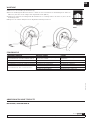
DESCRIPTION
Robust construction hose reel for high volume or high hose capacity
applications, depending on mounted power spring:
The mounted power spring version appears in the label placed on
the spool.
FLUIDS MAXIMUM HOSE CAPACITY
Air, water,
lubricants or
diesel fuel
1” 15 m 50´
3/4” 20-25 m 65-75´
1/2” 30 m 100´
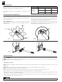
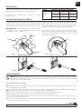
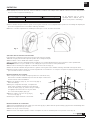
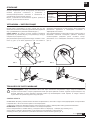
The reel can be wall, ceiling or floor mounted. To allow the hose to
always be optimally extended, the guide arms can be assembled in 6
different positions (Fig. 1).
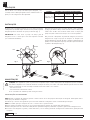
VERY IMPORTANT: Don´t try to change the guide arms position
without having the reel placed on a horizontal support surface (floor,
workbench, etc.).
Fig. 3
To position these guide arms, loosen and remove the screws (1) (Fig. 2)
in both arms. At this moment, the spool and the guide arms become
loose from the reel frame. Then, just position the guide arms in the
desired position and fix them with the same screws.
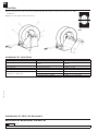
To position the hose stopper, take out the hose to the nearest blocking
ratchet position to the desired length. Loosen the stopper, place it in
the desired position and tighten the screws (Fig. 3).
1
FLOOR
WALL
CEILLING
Fig. 1 Fig. 2
MAINTENANCE
WARNING: Before carrying out any kind of maintenance, close the nearest shut off valve to the hose reel and open the dispensing valve
to relieve the pressure in the hose. The reel spring is under very high tension and can cause serious injury if it is released. Therefor, do not
attempt to service the spring inside the reel.
!
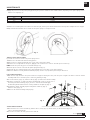
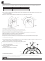
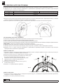
HOSE REPLACEMENT
NOTE: During hose installation, tighten the U-bolt just till the hose gets slightly deformed. Do not overtighten the U-bolt, since the hose could
be damaged.
1. Ensure the reel is firmly attached. Take the hose fully out and let the spool blocked by the ratchet mechanism.
NOTE: beware the spool to get loose and start turning freely.
2. Remove the U-bolt by loosening its nuts (1) and disconnect the hose from the swivel (2) by using two wrenches (Fig. 4).
3. Take away the hose from the spool and remove the hose stopper in order to use it with the new hose.
4. Connect the new hose to the swivel by using two wrenches. Place the U-bolt in such a way that it firmly holds the hose against the spool, and
pull the hose in order to unlock the ratchet (Fig. 4).
5. Allow the hose to slowly wind into the spool and ensure to finish with the whole hose inside the reel and the power spring with no tension (in
such a way that the spool does not try to turn).

3
R. 02/22 850 821
SAMOA Industrial, S.A. · Pol. Ind. Porceyo, I-14 · Camino del Fontán, 831 · 33392 - Gijón - Spain · Tel.: +34 985 381 488 · www.samoaindustrial.com
EN
2022_02_16-10:00
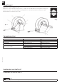
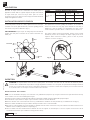
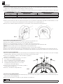
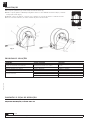
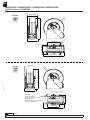
SWIVEL REPLACEMENT
1. Disconnect the hoses of the inlet shaft (1) and the swivel joint (2) (Fig. 7). On the swivel, use two wrenches (Fig. 4) in
order to avoid any shaft damage.
2. Loosen the set screw in the nut (3) and remove said nut.
MAINTENANCE
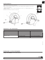
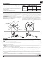
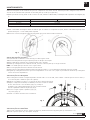
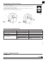
6. Apply the pre-tension to the power spring by turning the spool the number of turns indicated below, depending on the power spring version
and the hose length (Fig. 5):
HOSE LENGTH HIGH VOLUME POWER SPRING HIGH CAPACITY POWER SPRING
15 m +7 turns
20 - 25 m +5 turns
30 m +1 turns
Do not apply more tension than stated, as the power spring could be damaged.
7. Pass the hose end through the roller outlet to the desired length, lock the spool with the ratchet in the nearest position and place the hose stopper.
8. Fully unwind and rewind the hose to make sure the power spring is correctly tensioned.
SPRING LOAD ADJUSTMENT
If you wish to increase or decrease the power spring tension:
1. Pull the hose out till the first ratchet locking position.
2. Remove the hose stopper and pull the hose out in order to unlock the ratchet.
3. Allow the hose to fully wind into the spool, applying some counter-force in order to avoid the spool to turn freely.
NOTE: beware the spool may get loose and start turning freely.
4. Turn the spool to increase or decrease the power spring tension (Fig. 5).
5. Pass again the hose end through the roller outlet and place the hose stopper in the desired position.
6. Make sure that the hose fully winds and unwinds properly. If it does not, repeat the previous steps until it does.
LATCH REPLACEMENT
1. With the hose fully wound on the spool and the hose stopper touching the rollers, turn the spool enought to be able to reach the ratchet
assembly. Make sure to avoid the spool to turn freely, blocking it safely.
2. Loosen the 2 bolts (1) (Fig. 6), and the 4 nuts (2) (Fig. 6). Remove the ratchet assembly.
3. Clean the components, or replace the ratchet assembly with a new one. In the case of
unscrewing the ratchet shaft (3) (Fig. 6), be sure to clean the thread and apply
medium-strength threadlocker before screwing it back into the plate (4) (Fig. 6).
4. Assemble the ratchet assembly in place and tight the 2 bolts (1) (Fig. 6).
and the 4 nuts (2) (Fig. 6).
5. Make sure the ratchet assembly works properly.
Fig. 4
Fig. 5
Fig. 6
1
2
1
2
4
3

4850 821 R. 02/22
SAMOA Industrial, S.A. · Pol. Ind. Porceyo, I-14 · Camino del Fontán, 831 · 33392 - Gijón - Spain · Tel.: +34 985 381 488 · www.samoaindustrial.com
EN
2022_02_16-10:00
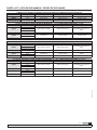
TROUBLESHOOTING
SYMPTOM POSSIBLE CAUSES SOLUTION
Hose does not rewind Spring is not tensioned enough Increase spring tension
Leaking hose reel Hose has a hole or is damaged Replace the hose
Leaking swivel Damaged swivel rings Replace the swivel rings
Hose does not extend out as much as required Spring is over tensioned Decrease spring tension
Hose reel does not latch
Damaged ratchet Replace the ratchet
Ratchet not fitted Assembly the ratchet properly
Damaged spring ratchet Change the ratchet spring
DIMENSIONS AND PARTS LIST
SPARE PARTS SEE PAGE 20 AND 22
3. Remove the screws (4) and the arm (5).
4. Remove the swivel and replace it with a new one, or replace the seals. Make sure the seals are placed correctly (Fig. 8).
5. Grease the interior of the swivel and place it carefully back on the shaft until it touches the bearing on the spool.
6. Place back the rest of parts in reverse order.
(Section of the swivel)
Fig. 8
Fig. 7
MAINTENANCE

5
R. 02/22 850 821
SAMOA Industrial, S.A. · Pol. Ind. Porceyo, I-14 · Camino del Fontán, 831 · 33392 - Gijón - Spain · Tel.: +34 985 381 488 · www.samoaindustrial.com
2022_02_16-10:00
ES
INSTALACIÓN-MODO DE EMPLEO
DESCRIPCIÓN
Enrollador de manguera abierto de construcción muy robusta para aplicaciones
de gran caudal o de gran capacidad de manguera, según resorte:
La versión de resorte instalado aparece indicada en la etiqueta
situada en el disco.
El enrollador puede montarse en pared, techo o suelo. Para conseguir
que la manguera sea extendida siempre de manera óptima, los brazos
guía de manguera pueden montarse en 6 posiciones diferentes (Fig. 1).
MUY IMPORTANTE: no intente cambiar la posición de los brazos guía
de manguera sin tener el enrollador asentado sobre una superficie
horizontal (suelo, banco de trabajo, etc).
Fig. 3
Para posicionar los brazos guía, es necesario aflojar y quitar los tornillos (1)
(Fig. 2) en ambos brazos. En ese momento el tambor junto con los brazos
guía quedan sueltos del bastidor. Se procede entonces a cambiar los brazos
a la posición deseada y a volver a fijarlos con los mismos tornillos.
Para posicionar el tope de manguera, desenrolle la manguera hasta
llegar a la posición de bloqueo del trinquete más próxima a la longitud
deseada. Afloje el tope de manguera, colóquelo en la posición deseada
y apriete los tornillos (Fig. 3).
1
Fig. 1 Fig. 2
MANTENIMIENTO
ATENCIÓN: Antes de empezar cualquier tipo de mantenimiento, cierre la válvula más cercana al enrollador y abra la válvula de salida para
soltar la presión en la manguera. El resorte está bajo muy alta tensión y puede producir graves heridas si se suelta. Por lo tanto, no intente
dar servicio al resorte dentro del enrollador.
!
SUSTITUCIÓN DE LA MANGUERA
NOTA: Durante la instalación de la manguera, apriete el abarcón sólo hasta deformar ligeramente la manguera. Evite apretar el abarcón en exceso
pues la manguera puede llegar a dañarse.
1. Asegúrese de que el enrollador de manguera esté firmemente sujeto. Desenrolle totalmente la manguera y deje el tambor fijado por el trinquete.
NOTA: Tenga cuidado para que el trinquete no se suelte y el enrollador empiece a girar libremente.
2. Retire el abarcón aflojando sus tuercas (1) y desconecte la manguera de la rótula (2) utilizando dos llaves (Fig. 4).
3. Extraiga la manguera del tambor y desmonte el tope de manguera para usarlo con la manguera nueva.
4. Conecte la nueva manguera a la rótula utilizando dos llaves, coloque el abarcón de modo que sujete la manguera contra el tambor firmemente,
y tire de ella para soltar el trinquete (Fig. 4).
5. Deje la manguera recogerse lentamente y asegúrese de terminar con toda la longitud enrollada y el resorte sin tensión (dejando el tambor
neutro, de modo que no intente girar más).
PARED
SUELO
TECHO
FLUIDOS MÁXIMAS CAPACIDADES DE MANGUERA
Aire, agua,
lubricantes o
gasóleo
1” 15 m 50´
3/4” 20-25 m 65-75´
1/2” 30 m 100´

6850 821 R. 02/22
SAMOA Industrial, S.A. · Pol. Ind. Porceyo, I-14 · Camino del Fontán, 831 · 33392 - Gijón - Spain · Tel.: +34 985 381 488 · www.samoaindustrial.com
2022_02_16-10:00
ES
MANTENIMIENTO
6. Aplique la pre-tensión al resorte, girando el tambor el nº de vueltas indicado, dependiendo del resorte y la longitud de manguera (Fig. 5):
LONGITUD DE MANGUERA RESORTE HIGH VOLUME RESORTE HIGH CAPACITY
15 m +7 vueltas
20 - 25 m +5 vueltas
30 m +1 vueltas
No se debe aplicar más tensión de la indicada, pues el resorte puede resultar dañado.
7. Pase el extremo de la manguera a través de la salida de guía de rodillos la longitud deseada, deje el tambor trincado en la posición más cercana
y coloque el tope de manguera.
8. Desenrolle y enrolle la manguera totalmente para comprobar que el resorte está tensado de forma correcta.
AJUSTE DE LA TENSIÓN DEL RESORTE
Si desea aumentar o disminuir la tensión del resorte, proceda de la siguiente forma:
1. Desenrolle la manguera hasta llegar a la primera posición de bloqueo del trinquete.
2. Quite el tope de manguera y tire de la manguera para soltar el trinquete.
3. Permita que la manguera se enrolle totalmente en el tambor, reteniéndola lo suficiente para que éste no gire libremente.
NOTA: Tenga cuidado de que la bobina no empiece a girar libremente.
4. Haga girar la bobina para incrementar o disminuir la tensión (Fig. 5).
5. Vuelva a pasar el extremo de la manguera a través de la salida de rodillos y coloque el tope de manguera en la posición deseada.
6. Asegúrese de que la manguera se desenrolla y que se recoge completamente. Si no, repita el procedimiento hasta que lo haga.
SUSTITUCIÓN DEL TRINQUETE
1. Con la manguera enrollada y el tope de manguera apoyado en los rodillos de salida, gire el tambor lo suficiente como para tener acceso al
trinquete, y asegúrese de impedir el giro del tambor de forma segura.
2. Desenrosque los 2 tornillos (1) (Fig. 6), y las 4 tuercas (2) (Fig. 6). Retire el conjunto.
3. Limpie los componentes del trinquete, o sustitúyalo por un conjunto trinquete nuevo.
En el caso de desenroscar el eje del trinquete (3) (Fig. 6), asegúrese
de limpiar la rosca y aplicar fijador de fuerza media previo a roscarlo
de nuevo sobre la chapa (4) (Fig. 6).
4. Colóquelo en su lugar y apriete los tornillos (1) (Fig. 6),
y las tuercas (2) (Fig. 6).
5. Verifique que el trinquete funciona correctamente.
SUSTITUCIÓN DE LA RÓTULA
1. Desconecte las mangueras en la acometida (1) y en la rótula (2) (Fig. 7). En la rótula utilice dos llaves (Fig. 4) para evitar dañar el eje.
2. Afloje el prisionero de la tuerca (3) y desenrosque dicha tuerca.
Fig. 4 Fig. 5
Fig. 6
1
2
1
2
4
3

7
R. 02/22 850 821
SAMOA Industrial, S.A. · Pol. Ind. Porceyo, I-14 · Camino del Fontán, 831 · 33392 - Gijón - Spain · Tel.: +34 985 381 488 · www.samoaindustrial.com
2022_02_16-10:00
ES
(Sección de la rótula)
Fig. 8
ANOMALÍAS Y SUS SOLUCIONES
SÍNTOMA POSIBLES CAUSAS SOLUCIÓN
El enrollador no recoge El muelle ha perdido tensión o se ha roto De tensión al resorte o reemplácelo
La manguera pierde fluido Manguera con poro o rota Cambie la manguera
La rótula pierde fluido Rótula deteriorada Cambie la rótula
La manguera no sale todo lo que debería Demasiada tensión en el resorte Quite tensión al resorte
El enrollador no trinca
Trinquete deteriorado Cambie el trinquete
Trinquete fuera de su lugar Coloque el trinquete adecuadamente
Muelle trinquete deteriorado Sustituya el muelle del trinquete
DIMENSIONES Y LISTA DE RECAMBIOS
DIBUJO DE RECAMBIOS EN LA PÁGINA 20 Y22
Fig. 7
MANTENIMIENTO
3. Desenrosque los tornillos (4) y retire el brazo (5).
4. Retire el cuerpo de rótula y sustitúyala por una nueva o bien sustituya las juntas asegurándose de que estén en
la posición correcta (Fig. 8).
5. Engrase el interior de la rótula e insértela cuidadosamente de nuevo en el eje hasta que haga tope con el
rodamiento del disco.
6. Vuelva a colocar el resto de elementos en orden inverso.

8850 821 R. 02/22
SAMOA Industrial, S.A. · Pol. Ind. Porceyo, I-14 · Camino del Fontán, 831 · 33392 - Gijón - Spain · Tel.: +34 985 381 488 · www.samoaindustrial.com
2022_02_16-10:00
FR
INSTALLATION-MODE D’EMPLOI
DESCRIPTION
Enrouleur de tuyau ouvert de construction très robuste pour les
applications à haut débit ou à grande capacité de tuyau. Enroulement
de tuyau assisté par ressort au moyen d’une paire de ressorts.
Construction en acier avec finition en résine de polyester. Particulièrement
adapté aux applications lourdes.
L’enrouleur peut être monté sur le mur, le plafond ou au sol. Pour que
le flexible soit toujours guidé idéalement, les bras de guidage peuvent
être montés en 6 positions différentes (Fig. 1).
TRES IMPORTANT: Ne pas essayer de changer la position des bras de
guidage sans avoir placé l’enrouleur sur une surface horizontale (sol,
établi, etc).
Fig. 3
Pour positionner les bras de guidage du flexible il est nécessaire de
desserrer et de retirer les vis (1) (Fig. 2) des deux bras. A cette étape, le
tambour et le bras de guidage sont désolidarisés du cadre. Placer
ensuite les bras à la position désirée et refixez-les avec les mêmes vis.
Pour régler la butée de blocage du flexible, dérouler celui-ci jusqu’à
atteindre la position de verrouillage du cliquet la plus proche de la
longueur désirée. Desserrez la butée, glissez la dans la position
souhaitée et serrez les vis (Fig. 3).
1
Fig. 1 Fig. 2
ENTRETIEN
ATTENTION: Il est primordial de fermer la vanne la plus proche de l’enrouleur et d’ouvrir celle de sortie afin de relâcher la pression
contenue dans le flexible avant de procéder à tout type d’opération d’entretien. Le ressort peut être potentiellement dangereux dans la
mesure où il est soumis à de fortes tensions et peut causer des blessures si ce dernier se relâche. Par conséquent, nous conseillons vivement
de ne jamais toucher le ressort qui se trouve à l’intérieur de l’enrouleur.
!
REMPLACEMENT DU FLEXIBLE
NOTE : Lors de l’installation du tuyau, serrez le boulon en U graduellement jusqu’à ce que le tuyau se déforme très légèrement. Évitez de trop
serrer le boulon en U car cela endommagerait le tuyau.
1. Assurez-vous que l’enrouleur soit fermement fixé. Dérouler entièrement le flexible et laissez-le tambour bloqué par le cliquet.
Faites attention à ne pas relâcher le cliquet et que l’enrouleur commence à tourner librement.
2. Retirez les boulons en U en desserrant leurs écrous (1) et débranchez le flexible de la rotule pivotante (2) en utilisant deux clés (Fig. 4).
3. Retirez le flexible du tambour ainsi que la butée d’arrêt pour l’utiliser avec le nouveau flexible.
4. Raccordez le nouveau flexible à la rotule pivotante en utilisant deux clés. Placer les boulons en U pour maintenir le flexible fermement sur le
tambour et tirez le flexible pour libérer le cliquet (Fig. 4).
5. Laisser le flexible s’enrouler lentement dans le tambour sur toute sa longueur en s’assurant que le ressort ne soit plus sous tension à la fin de
l’enroulement (de manière que le tambour n’essaye plus de tourner).
MUR
SOL
PLAFOND
FLUIDES CAPACITÉ MAXIMALE DU FLEXIBLE
Air, eau, huile ou
gazole
1” 15 m 50´
3/4” 20-25 m 65-75´
1/2” 30 m 100´

9
R. 02/22 850 821
SAMOA Industrial, S.A. · Pol. Ind. Porceyo, I-14 · Camino del Fontán, 831 · 33392 - Gijón - Spain · Tel.: +34 985 381 488 · www.samoaindustrial.com
2022_02_16-10:00
FR
ENTRETIEN
6. Pour appliquer la pré-tension du ressort, tourner le tambour le nombre de tours indiqués dans le tableau ci-dessous en fonction de la puissance
du ressort et de la longueur du flexible (Fig. 5):
Longueur de flexible Ressort Grand Volume Ressort Haute Capacité
15 m +7 tours
20 - 25 m +5 tours
30 m +1 tours
7. Passez l’extrémité du tuyau à travers le guide de sortie à galets et dérouler celui-ci jusqu’à atteindre la position de verrouillage du cliquet la plus
proche de la longueur désirée. Fixer la butée de blocage du flexible.
8. Dérouler et enrouler complètement le flexible pour vérifier que le ressort est tendu correctement.
AJUSTAGE DE LA TENSION DU RESSORT
Pour augmenter ou diminuer la tension du ressort, procéder de la façon suivante:
1. Dérouler le tuyau pour atteindre la première position de verrouillage du cliquet.
2. Retirer la butée et tirez le flexible afin de libérer le cliquet.
3. Laissez le flexible s’enrouler complètement dans le tambour en le retenant suffisamment pour que l’enrouleur ne tourne pas librement.
REMARQUE: Attention à ce que le flexible ne vous échappe pas et que l’enrouleur ne tourne pas librement.
4. Faites tourner l’enrouleur pour augmenter ou diminuer la tension du ressort (Fig. 5).
5. Passez de nouveau l’extrémité du tuyau à travers le guide de sortie à galets et fixer la butée de blocage du flexible à la longueur désirée.
6. Assurez-vous que le tuyau se déroule et s’enroule intégralement et correctement. Si ce n’est pas le cas répétez les étapes précédentes jusqu’à ce
que l’enrouleur fonctionne correctement.
REMPLACEMENT DU CLIQUET
1. Avec le tuyau enroulé et la butée de tuyau reposant sur les rouleaux de sortie,
faites tourner le tambour suffisamment pour accéder au cliquet et assurez-vous
de bien arrêter la rotation du tambour.
2. Dévissez les 2 boulons (1) (Fig. 6), et les 4 écrous (2) (Fig. 6).
Retirez l’assemblage.
3. Nettoyez les composants du cliquet, ou remplacez-les
par un nouvel ensemble de cliquet. En cas de dévissage
de l’axe du cliquet (3) (Fig. 6), veillez à nettoyer le filetage
et à appliquer du frein-filet de force moyenne avant
de le revisser dans la plaque (4) (Fig. 6).
4. Mettez-le en place et serrez les vis (1) (Fig. 6),
et les écrous (2) (Fig. 6).
5. Vérifiez que le cliquet fonctionne correctement.
REMPLACEMENT DE LA ROTULE
1. Déconnecter le flexible dans de l’axe central (1) et de la rotule (2) (Fig. 7). Utiliser deux clés pour la rotule (Fig. 4) pour éviter d’endommager l’axe.
2. Desserrer l’écrou prisonnier (3) et le retirer.
3. Dévissez les vis (4) et retirer le bras (5).
4. Retirer la rotule et la remplacer par une nouvelle ou remplacer les joints en s’assurant qu’ils sont en position correcte (Fig. 8).
Fig. 4 Fig. 5
Ne pas appliquer plus de tension
qu’indiqué dans le tableau, faute de
quoi le ressort peut être endommagé.
Fig. 6
1
2
1
2
4
3

10 850 821 R. 02/22
SAMOA Industrial, S.A. · Pol. Ind. Porceyo, I-14 · Camino del Fontán, 831 · 33392 - Gijón - Spain · Tel.: +34 985 381 488 · www.samoaindustrial.com
2022_02_16-10:00
FR
ANOMALIES ET SOLUTIONS
SYMPTÔMES CAUSES POSSIBLES SOLUTION
Rembobinage du flexible incomplet Le ressort à perdu de la tension ou s'est
rompu
Augmenter la tension du ressort ou le
remplacer
Fuite sur le flexible Flexible poreux ou cassé Remplacer le flexible
Fuite de la rotule La rotule est détériorée Remplacer la rotule
Le flexible ne se déroule pas complètement Trop de tension sur le ressort Diminuer la tension
L'enrouleur ne se bloque pas
Le cliquet est détérioré Changer le cliquet
Le cliquet s'est désaxé Replacer le cliquet correctement
Le ressort du cliquet est abimé Remplacer le ressort du cliquet
DIMENSIONS ET PIÈCES DE RECHANGE
DESSIN DE PIECES DE RECHANGE, PAGE 20 ET 22
5. Graisser l’intérieur de la rotule et insérez-la soigneusement dans l’axe jusqu’à ce qu’elle vienne en butée sur le disque
du tambour.
6. Replacer le reste des pièces dans l’ordre inverse.
(Section de la rotule)
Fig. 8
Fig. 7
ENTRETIEN

11
R. 02/22 850 821
SAMOA Industrial, S.A. · Pol. Ind. Porceyo, I-14 · Camino del Fontán, 831 · 33392 - Gijón - Spain · Tel.: +34 985 381 488 · www.samoaindustrial.com
2022_02_16-10:00
DE
MONTAGE-INBETRIEBNAHME
BESCHREIBUNG
Automatik-Schlauchaufroller, offen, schwere Qualität, je nach Feder
geeignet für den Einsatz bei großen Fördermengen bzw. langen
Förderstrecken:
Der jeweils eingebaute Trommelfedertyp ist auf dem Etikett an der
Trommel angegeben.
Der Schlauchaufroller wird direkt an die Decke, den Boden oder die
Wand montiert. Damit der Schlauch in jedem Fall in optimalem Winkel
ein- und ausgezogen werden kann, können die Führungsarme in 6
verschiedenen Positionen montiert werden (Abb. 1):
SEHR WICHTIG: Die Position der Führungsarme darf nur verändert
werden, wenn sich der Automatik-Schlauchaufroller auf einer ebenen
Oberfläche befindet (Boden, Werkbank, etc.).
Bild 3
Um die Führungsarme in die gewünschte Stellung zu bringen, müssen
die Schrauben (1) (Abb. 2) an beiden Armen gelöst und entfernt werden,
so dass die Trommel zusammen mit den Führungsarmen vom Rahmen
getrennt ist. Daraufhin können die Arme in die gewünschte Stellung
gebracht und mit denselben Schrauben wieder befestigt werden.
Um den Schlauchstopper einzustellen, ziehen Sie den Schlauch bis zur
Arretierung aus, die der gewünschten Länge am nächsten ist. Lösen Sie
den Schlauchstopper, bringen Sie ihn in die gewünschte Position und
ziehen Sie die Schrauben wieder an (Abb. 3).
1
Bild 1 Bild 2
WARTUNG
ACHTUNG: Vor Beginn jeglicher Arbeiten am Gerät die Zufuhr abschalten und das Auslaufventil öffnen, um den Flüssigkeitsdruck
abzubauen. Der Feder steht immer unter Spannung. Zur Verringerung des Risikos von schweren Verletzungen:
- versuchen Sie nicht die Feder zu entfernen.
- versuchen Sie nicht die Feder zu ersetzen oder zu reparieren.
!
AUSTAUSCH DES SCHLAUCHES
ACHTUNG: Ziehen Sie bei der Montage des Schlauches den U-Bolzen so fest an, bis der Schlauch sich leicht verformt. Zu festes Anziehen des
U-Bolzen kann zu einer Beschädigung des Schlauches führen!
1. Versichern Sie sich, dass der Automatik-Schlauchaufroller sicher aufliegt. Ziehen Sie den Schlauch komplett aus und arretieren Sie die
Schlauchtrommel.
HINWEIS: Achten Sie darauf, dass sich die Sperrklinke nicht löst und der Automatik-Schlauchaufroller beginnt, sich ungehindert zu drehen.
2. Entfernen Sie den Bolzen, indem sie die Muttern (1), mit denen er befestigt ist, lösen, und trennen Sie den Schlauch mittels zweier Schlüssel
vom Drehgelenk (2) (Abb. 4).
3. Ziehen Sie den Schlauch aus der Schlauchtrommel heraus und montieren Sie den Schlauchstopper ab, um ihn für den neuen Schlauch wieder
zu verwenden.
4. Verbinden Sie den neuen Schlauch mittels zweier Schlüssel mit dem Drehgelenk. Bringen Sie den Bolzen so an, dass der Schlauch fest mit der
Trommel verbunden ist, und ziehen Sie am Schlauch, um ihn auszurasten.
WAND
BODEN
DECKE
MEDIUM MAXIMALE SCHLAUCHLEISTUNG
Luft, Wasser, Öl
oder Diesel
1” 15 m 50´
3/4” 20-25 m 65-75´
1/2” 30 m 100´

12 850 821 R. 02/22
SAMOA Industrial, S.A. · Pol. Ind. Porceyo, I-14 · Camino del Fontán, 831 · 33392 - Gijón - Spain · Tel.: +34 985 381 488 · www.samoaindustrial.com
2022_02_16-10:00
DE
WARTUNG
5. Lassen Sie den Schlauch langsam einziehen und versichern Sie sich, dass er in seiner ganzen Länge eingezogen wird und die Trommelfeder
entspannt ist (so dass die Schlauchtrommel aufhört, sich drehen zu wollen).
6. Spannen Sie die Schlauchfeder vor, indem Sie abhängig vom Trommelfedertyp und der Schlauchlänge die angegebene Anzahl von Drehungen
an der Schlauchtrommel ausführen (Abb. 5):
SCHLAUCHLÄNGE TROMMELFEDER FÜR HOHE
FÖRDERLEISTUNG
TROMMELFEDER FÜR LANGE
SCHLAUCHLÄNGEN
15 m +7 Drehungen
20 - 25 m +5 Drehungen
30 m +1 Drehungen
Es darf keine höhere Spannung als die angegebene aufgebaut werden, da sonst die Trommelfeder beschädigt werden kann.
7. Führen Sie das Schlauchende durch die Schlauch- führungsrollen, bis die gewünschte Schlauchlänge außerhalb des Schlauchaufrollers erreicht
ist, arretieren Sie die Trommel in der nächstgelegenen Position und bringen Sie den Schlauchstopper an.
8. Ziehen Sie den Schlauch komplett aus und wieder ein, um zu prüfen, ob die Trommelfeder korrekt gespannt ist.
REGULIERUNG DER FEDERSPANNUNG
Möchten Sie die Federspannung erhöhen oder reduzieren, gehen Sie Folgendermaßen vor:
1. Ziehen Sie den Schlauch so weit aus, bis Sie zur ersten Arretierung gelangen.
2. Entfernen Sie den Schlauchstopper und ziehen Sie am Schlauch, um die Arretierung zu lösen.
3. Ziehen Sie den kompletten Schlauch kontrolliert ein, so dass sich die Schlauchtrommel nicht ungehindert dreht.
HINWEIS: Achten Sie darauf, dass sich die Schlauchtrommel nicht ungehindert dreht.
4. Drehen Sie die Schlauchtrommel, um die Federspannung zu erhöhen oder zu reduzieren (Abb. 5).
5. Führen Sie das Schlauchende wieder durch die Schlauchführungsrollen und bringen Sie den Schlauchstopper an der gewünschten Stelle an.
6. Stellen Sie sicher, dass sich der Schlauch komplett ein- und ausziehen lässt. Wenn dies nicht der Fall ist, wiederholen Sie die Schritte, bis dies geht.
AUSTAUSCH DES DREHGELENKS
1. Lösen Sie die Schlauchverbindungen am Schlaucheingang (1) und am Drehgelenk (2) (Abb. 7). Benutzen Sie zwei Schlüssel beim Drehgelenk,
damit die Achse nicht beschädigt wird.
2. Lösen Sie die Stellschraube an der Mutter (3) und schrauben Sie die Mutter ab.
Bild 4 Bild 5
AUSTAUSCH DER SPERRKLINKE
1. Wenn der Schlauch aufgerollt ist und der Schlauchanschlag auf den Ausgangsrollen aufliegt, drehen Sie die Trommel so weit, dass Sie Zugang
zur Ratsche haben, und achten Sie darauf, dass sich die Trommel nicht mehr drehen kann.
2. Lösen Sie die 2 Schrauben (1) (Abb. 6), und die 4 Muttern (2) (Abb. 6).
Entfernen Sie die Baugruppe.
3. Reinigen Sie die Komponenten der Ratsche, oder ersetzen
Sie sie durch eine neue Ratschenbaugruppe.
Wenn Sie die Ratschenwelle (3) abschrauben (Abb. 6),
müssen Sie das Gewinde reinigen und eine mittelfeste
Schraubensicherung auftragen, bevor Sie sie wieder
in die Platte (4) einschrauben (Abb. 6).
4. Setzen Sie ihn ein und ziehen Sie die Schrauben (1) (Abb. 6)
und die Muttern (2) (Abb. 6) an.
5. Prüfen Sie, ob die Ratsche richtig funktioniert.
1
2
1
2
4
3
Bild 6

13
R. 02/22 850 821
SAMOA Industrial, S.A. · Pol. Ind. Porceyo, I-14 · Camino del Fontán, 831 · 33392 - Gijón - Spain · Tel.: +34 985 381 488 · www.samoaindustrial.com
2022_02_16-10:00
DE
FEHLERSUCHE
PROBLEMBESCHREIBUNG MÖGLICHE GRÜNDE LÖSUNG
Der Schlauchaufroller zieht den Schlauch nicht ein Die Trommelfeder hat ihre Spannung
verloren oder ist defekt
Die Trommelfeder nachspannen oder
austauschen
Der Schlauch ist undicht Poröser oder defekter Schlauch Schlauch austauschen
Das Drehgelenk ist undicht Drehgelenk beschädigt Drehgelenk austauschen
Der Schlauch lässt sich nicht wie gewünscht ausziehen Trommelfeder zu sehr gespannt Trommelfeder entspannen
Der Schlauchaufroller lässt sich nicht arretieren
Sperrklinke beschädigt Sperrklinke austauschen
Sperrklinke ausgehängt Sperrklinke korrekt anbringen
Sperrklinkenfeder beschädigt Sperrklinkenfeder austauschen
ABMESSUNGEN UND TEILELISTE
ERSATZTEIL, SEITE 20 UND 22
WARTUNG
3. Entfernen Sie die Schrauben (4) und den Arm (5).
4. Ziehen Sie das Drehgelenk ab und ersetzen Sie es durch ein neues oder tauschen Sie die Dichtungen aus. Stellen Sie
dabei sicher, dass diese an der richtigen Stelle angebracht werden (Abb. 8).
5. Schmieren Sie das Innere des Drehgelenks ab und führen Sie es vorsichtig wieder in die Achse ein, bis es an das
Trommellager stößt.
6. Bringen Sie die restlichen Komponenten in umgekehrter Reihenfolge wieder an.
(Drehgelenk)
Bild 8
Bild 7

14 850 821 R. 02/22
SAMOA Industrial, S.A. · Pol. Ind. Porceyo, I-14 · Camino del Fontán, 831 · 33392 - Gijón - Spain · Tel.: +34 985 381 488 · www.samoaindustrial.com
2022_02_16-10:00
PT
INSTALAÇÃO
DESCRIÇÃO
Carretel aberto com retração automática para mangueira, com
construção muito robusta para grandes vazões de abastecimento ou
aplicações com mangueiras de alta capacidade:
O carretel pode ser montado em parede, teto ou solo. Para conseguir que
a mangueira seja estendida sempre de maneira correta, as braços guia de
mangueira podem ser montados em 6 posições diferentes (Fig. 1).
IMPORTANTE: não tente trocar a posição dos braços guia da
mangueira sem ter o carretel preso sobre uma superfície horizontal
(solo ou bancada de trabalho).
Fig. 3
Para posicionar os braços guia, é necessário afrouxar e retirar os parafusos
(1) (Fig. 2), de ambos os braços. Neste momento a roda e os braços guia
estarão soltos da base neste momento. Então trocar os braços para
posição desejada e voltar a fixar os braços com os mesmos parafusos.
Para posicionar a abraçadeira de parada da mangueira, desenrolar a
mangueira até chegar na posição de bloqueio do trinquete mais
próxima da distancia desejada. Afrouxar os parafusos da abraçadeira de
parada, colocar a abraçadeira na posição desejada e apertar novamente
os parafusos da abraçadeira (Fig. 3).
1
Fig. 1 Fig. 2
MANUTENÇÃO
ATENÇÃO: Este equipamento é para uso profissional. Acompanhar sempre a trama da mangueira. Não ultrapassar a pressão de trabalho.
Usar fluídos compatíveis com os materiais usados na construção do carretel, em contato com o fluido. Eliminar a pressão interior do fluido
durante a manutenção. A mola está sempre em baixa tensão. Para reduzir o risco de danos:
- não remover a mola.
- não tentar trocar nem manusear a mola.
O uso com fluidos não indicados podem causar graves danos.
!
SUBSTITUIÇÃO DA MANGUEIRA
NOTA: Durante a instalação da mangueira, apertar o fixador somente até ter uma pequena deformação na mangueira. Evitar apertar muito o
fixador que pode danificar a mangueira.
1. Certificar que o carretel está seguramente preso. Desenrolar totalmente a mangueira e deixar a roda travada pelo trinquete.
NOTA: Ter cuidado para que o trinquete não solte e o carretel comece a girar livremente.
2. Retirar o fixador, afrouxando as porcas (1) e desconectar a mangueira do giratório (2), usando duas chaves (Figura 4).
3. Extrair a mangueira da roda e desmontar a abraçadeira de parada da mangueira, afrouxando os parafusos, para usa-la na mangueira nova.
4. Conectar a nova mangueira no giratório, usando duas chaves, colocar o fixador, prendendo a mangueira na roda firmemente, puxar para soltar
o trinquete.
PAREDE
SOLO
TETO
FLUIDOS MÁXIMAS CAPACIDADES DE MANGUEIRA
Água, óleo diesel
e lubrificante e ar
1” 15 m 50´
3/4” 20-25 m 65-75´
1/2” 30 m 100´

15
R. 02/22 850 821
SAMOA Industrial, S.A. · Pol. Ind. Porceyo, I-14 · Camino del Fontán, 831 · 33392 - Gijón - Spain · Tel.: +34 985 381 488 · www.samoaindustrial.com
2022_02_16-10:00
PT
Fig. 4 Fig. 5
MANTENIMIENTO
5. Deixar a mangueira enrolar lentamente até que todo comprimento esteja dentro da roda. Certificar que toda a mangueira esteja enrola e a
esteja mola sem nenhuma tensão (deixando a roda neutra, para que ela não possa girar mais).
6. Aplicar a pré-tensão na mola, girando a roda no numero de voltas, indicados na tabela abaixo, indicada para cada comprimento de mangueira (Fig.
5).:
LONGITUD DE MANGUERA RESORTE HIGH VOLUME RESORTE HIGH CAPACITY
15 m +7 vueltas
20 - 25 m +5 vueltas
30 m +1 vueltas
Não aplicar mais tensão na mola do que a indicada acima. O não cumprimento desta orientação pode danificar a mola.
7. Passar a extremidade da mangueira através da saída do guia dos rodilhos no comprimento desejado, deixar a roda travada na posição mais
próxima de bloqueio e colocar a abraçadeira de parada.
8. Desenrolar e enrolar a mangueira totalmente para garantir que a mola está tensionada corretamente.
AJUSTE DA TENSÃO DA MOLA
Se desejar aumentar ou diminuir a tensão da mola, proceda da seguinte forma:
1. Desenrolar a mangueira até chegar na primeira posição de bloqueio do trinquete.
2. Retirar a abraçadeira de parada e tirar a mangueira para soltar o trinquete.
3. Permitir que a mangueira enrole totalmente na roda, tensionar o suficiente para que a roda gire livremente
NOTA : Ter cuidado para que roda não comece a girar sozinha.
4. Fazer a roda girar para aumentar ou diminuir a tensão da mola.
5. Voltar a passar a extremidade da mangueira através da saída dos rodilhos e colocar a abraçadeira de parada na posição desejada.
6. Assegurar que a mangueira desenrola e que enrola completamente. Se isto não ocorrer, repetir os procedimentos acima até que a mangueira
enrolar e desenrolar completamente.
SUBSTITUIÇÃO DO GIRATÓRIO
1. Desconectar a mangueira (1) presa ao giratório (2) (Figura 7), utilizando duas chaves (Figura 4) para que não danificar o eixo.
2. Afrouxar a porca de aperto (3) e desrosquear esta porca.
SUBSTITUIÇÃO DO TRINQUETE
1. Com a mangueira enrolada e a mangueira parada a descansar sobre os rolos de saída, rodar o tambor o suficiente para ter acesso à catraca, e
ter a certeza de parar o tambor de girar com segurança.
2. Desaperte os 2 parafusos (1) (Fig. 6), e as 4 porcas (2) (Fig. 6). Retirar a montagem.
3. Limpar os componentes da catraca, ou substituir por um novo conjunto de catraca.
No caso de desenroscar o eixo da catraca (3) (Fig. 6), certifique-se
de limpar a rosca e aplicar um bloqueador de rosca de média resistência
antes de a aparafusar novamente na placa (4) (Fig. 6).
4. Colocá-lo no lugar e apertar os parafusos (1) (Fig. 6),
e as porcas (2) (Fig. 6).
5. Verificar se a catraca está a funcionar correctamente.
1
2
1
2
4
3
Fig. 6

16 850 821 R. 02/22
SAMOA Industrial, S.A. · Pol. Ind. Porceyo, I-14 · Camino del Fontán, 831 · 33392 - Gijón - Spain · Tel.: +34 985 381 488 · www.samoaindustrial.com
2022_02_16-10:00
PT
PROBLEMAS E SOLUÇÕES
PROBLEMA CAUSAS POSSÍVEIS SOLUÇÃO
A mola do carretel não se movimenta A mola perdeu tensão ou se soltou Dar tensão a mola ou recoloca-la no lugar
correto
Há vazamento pela mangueira Mangueira está furada ou danificada Substituir a mangueira
Há perda de fluido pelo giratório Giratório danificado Substituir o giratório
A mangueira não desenrola totalmente A mola está com muita tensão Diminuir a tensão da mola
O carretel não trava
Trinquete danificado Substituir o conjunto do trinquete
Trinquete está fora do lugar Ajustar o trinquete no lugar adequado
Mola do trinquete está danificada Substituir o conjunto do trinquete
DIMENSÕES E PEÇAS DE REPOSIÇÃO
PEÇAS DE REPOSIÇÃO, PÁGINA 20 E 22
3. Desrosquear os parafusos (4) e retirar o braço da roda do carretel (5).
4. Retirar o corpo do giratório e substituir por um giratório. Ou se for o caso substituir somente as vedações, colocando-
as na posição correta. (Fig. 8).
5. Lubrificar o interior do giratório e inserir de novo o giratório no eixo até que alcance o rolamento da roda.
6. Colocar os demais elementos, na ordem contraria dos passos descritos acima.
(seção do giratorio)
Fig. 8
Fig. 7
MANUTENÇÃO

17
R. 02/22 850 821
SAMOA Industrial, S.A. · Pol. Ind. Porceyo, I-14 · Camino del Fontán, 831 · 33392 - Gijón - Spain · Tel.: +34 985 381 488 · www.samoaindustrial.com
2022_02_16-10:00
RU
УСТАНОВКА – ЭКСПЛУАТАЦИЯ
ОПИСАНИЕ
Катушка, обладающая прочной конструкцией, для обеспечения
большой пропускной способности и применения с
высокопроизводительными шлангами в зависимости от
установленной исполнительной пружины:
Версия установленной исполнительной пружины указана на
этикетке, расположенной на бобине.
Катушка может монтироваться на стены, потолок или пол. Для
обеспечения постоянного оптимального удлинения шланга держатели
могут устанавливаться в 6 различных положениях (рис. 1).
ОЧЕНЬ ВАЖНО: Не следует пытаться изменить положение
держателей, не установив катушку на горизонтальную опорную
поверхность (пол, верстак и пр.).
Для расположения данных держателей следует ослабить и снять
винты (1) (рис. 2) на обоих держателях. При этом бобина и
Рис. 3
держатель отсоединяются от рамы катушки. Затем необходимо
расположить держатели в необходимом положении и
зафиксировать их винтами.
Для позиционирования стопора шланга следует извлечь шланг в
ближайшее положение блокировки храпового механизма,
соответствующее требуемой длине. Ослабить стопор,
расположить его в необходимое положение и затянуть винты
(Рис. 3).
1
Рис. 1 Рис. 2
ТЕХНИЧЕСКОЕ ОБСЛУЖИВАНИЕ
ПРЕДУПРЕЖДЕНИЕ: Перед выполнением какого-либо вида технического обслуживания следует закрыть ближайший к
катушке отсечной клапан и открыть раздаточный клапан для сброса давления в шланге. Пружина катушки находится под
высоким давлением и может вызывать серьезные травмы при высвобождении. Таким образом, не следует пытаться
осуществлять обслуживание пружины внутри катушки.
!
ЗАМЕНА ШЛАНГА
ПРИМЕЧАНИЕ: Во время установки шланга затягивать U-образный болт, пока шланг не будет слегка деформирован. Не перетягивать
U-образный болт, так как это может привести к его повреждению.
1. Убедиться в надежности фиксации катушки. Полностью вытянуть шланг и заблокировать бобину храповым механизмом
ПРИМЕЧАНИЕ: остерегаться ослабления бобины и ее свободного вращения.
2. Снять U-образный болт, ослабив гайки (1), отсоединить шланг от шарнира (2) с помощью двух ключей (рис. 4).
3. Снять шланг с бобины и демонтировать стопор шланга для использования с новым шлангом.
4. Повернуть бобину для увеличения и уменьшения натяжения исполнительной пружины (рис. 5).
ПОТОЛОК
СТЕНА
ПОЛ
Среды Максимальная производительность шланга
Воздух, вода,
смазочные
материалы
или дизельное
топливо
1” 15 m 50´
3/4” 20-25 m 65-75´
1/2” 30 m 100´

18 850 821 R. 02/22
SAMOA Industrial, S.A. · Pol. Ind. Porceyo, I-14 · Camino del Fontán, 831 · 33392 - Gijón - Spain · Tel.: +34 985 381 488 · www.samoaindustrial.com
2022_02_16-10:00
RU
РЕГУЛИРОВКА НАГРУЗКИ ПРУЖИНЫ
5. Повторно пропустить конец шланга через выходное отверстие ролика и установить стопор в необходимое положение.
6. Убедиться в том, что шланг полностью наматывается и разматывается надлежащим образом. В противном случае повторить
предыдущие шаги до правильного срабатывания.
Длина шланга Исполнительная пружина максимального объема High Capacity power spring
15 м +7 оборотов
20 - 25 м +5 оборотов
30 м +1 оборотов
Не применять натяжение больше указанного, так как исполнительная пружина может быть повреждена.
7. Выпустить конец шланга через выходное отверстие ролика для получения необходимой длины, зафиксировать бобину с помощью
храпового механизма в ближайшем положении и установить стопор шланга.
8. Полностью размотать и вновь замотать шланг для обеспечения надлежащего натяжения исполнительной пружины.
РЕГУЛИРОВКА НАГРУЗКИ ПРУЖИНЫ
Если возникла необходимость увеличения и уменьшения натяжения исполнительной пружины:
1. Вытянуть шланг в первое положение блокировки храпового механизма.
2. Снять стопор шланга и вытянуть шланг для разблокировки храпового механизма.
3. Позволить шлангу полностью намотаться на бобину, применяя противодействующее усилие во избежание свободного вращения бобины.
ПРИМЕЧАНИЕ: остерегаться ослабления бобины и ее свободного вращения.
4. Повернуть бобину для увеличения и уменьшения натяжения исполнительной пружины (рис. 5).
5. Повторно пропустить конец шланга через выходное отверстие ролика и установить стопор в необходимое положение.
6. Убедиться в том, что шланг полностью наматывается и разматывается надлежащим образом. В противном случае повторить
предыдущие шаги до правильного срабатывания.
ЗАМЕНА ШАРНИРА
1. Отсоединить шланги от входного вала (1) и шарнирного соединения (2) (рис. 7). На шарнирном соединении использовать два гаечных
ключа (рис. 4), чтобы не повредить вал.
2. Ослабить и снять гайки установочных винтов (3).
Рис. 4 Рис. 5
ЗАМЕНА ЗАЩЕЛКИ
1. Когда шланг смотан, а ограничитель шланга лежит на выходных роликах, поверните барабан настолько, чтобы получить доступ к
трещотке, и убедитесь, что барабан надежно остановлен.
2. Открутите 2 винта (1) (рис. 6) и 4 гайки (2) (рис. 6). Снимите сборку.
3. Очистите компоненты храповика или замените его новым узлом.
В случае откручивания вала трещотки (3) (рис. 6),
обязательно очистите резьбу и нанесите фиксатор резьбы
средней прочности, прежде чем вкручивать его
обратно в пластину (4) (рис. 6).
4. Установите его на место и затяните винты (1) (рис. 6),
а также гайки (2) (рис. 6).
5. Убедитесь, что трещотка работает правильно.
1
2
1
2
4
3
Рис. 6

19
R. 02/22 850 821
SAMOA Industrial, S.A. · Pol. Ind. Porceyo, I-14 · Camino del Fontán, 831 · 33392 - Gijón - Spain · Tel.: +34 985 381 488 · www.samoaindustrial.com
2022_02_16-10:00
RU
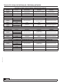
ДИАГНОСТИКА НЕИСПРАВНОСТЕЙ
Симптом Возможные причины Решение
Шланг не наматывается Недостаточное натяжение пружины Увеличить натяжение пружины
Наличие течи шланга Наличие отверстий или повреждений в
шланге Выполнить замену шланга
Утечка через шарнир Повреждение уплотнительных колец Выполнить замену уплотнительных колец
Шланг не вытягивается на нужную длину Чрезмерное натяжение пружины Уменьшить натяжение пружины
Шланг не фиксируется
Повреждение храпового механизма Выполнить замену храпового механизма
Отсутствие храпового механизма Выполнить установку храпового механизма
Повреждение пружины храпового
механизма
Выполнить замену пружины храпового
механизма
РАЗМЕРЫ, ПЕРЕЧЕНЬ ДЕТАЛЕЙ
СТРАНИЦА 20, 22
РЕГУЛИРОВКА НАГРУЗКИ ПРУЖИНЫ
3. Снять винты (4) и держатель (5).
4. Снять шарнир и заменить его на новый либо выполнить замену уплотнений. Убедиться в том, что
уплотнения установлены правильно (рис. 8).
5. Выполнить смазку внутренней части шарнира и аккуратно установить его обратно на вал, пока он не
будет соприкасаться с подшипником бобины.
6. Установить на место остальные детали в обратном порядке.
(Сечение шарнира)
Рис. 8
Рис. 7

20 850 821 R. 02/22
SAMOA Industrial, S.A. · Pol. Ind. Porceyo, I-14 · Camino del Fontán, 831 · 33392 - Gijón - Spain · Tel.: +34 985 381 488 · www.samoaindustrial.com
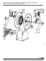
2022_02_16-10:00
RU
50
320 mm
668 mm
315,3 mm
635 mm
380 mm
Ø13 mm
290 mm
635 mm
320 mm
380 x 320 mm ø13 mm
220 x 130 mm ø10 mm
349,3 mm
668 mm
353 mm
635 mm
380 mm
635 mm
DIMENSIONS / DIMENSIONES / DIMENSIONS / DIMENSIONES /
ABMESSUNGEN / РАЗМЕРЫ
hole pattern
patrón de agujeros
gabarit de perçage
padrão de furos
диаметр окружности центров
отверстий под винты
15 m
50’
>15 m
>50’
HOSE REELS
HOSE REELS
A página está carregando...
A página está carregando...
A página está carregando...
A página está carregando...
-
 1
1
-
 2
2
-
 3
3
-
 4
4
-
 5
5
-
 6
6
-
 7
7
-
 8
8
-
 9
9
-
 10
10
-
 11
11
-
 12
12
-
 13
13
-
 14
14
-
 15
15
-
 16
16
-
 17
17
-
 18
18
-
 19
19
-
 20
20
-
 21
21
-
 22
22
-
 23
23
-
 24
24


Samoa 508244 Instructions Manual
- Tipo
- Instructions Manual
em outras línguas
- español: Samoa 508244
- français: Samoa 508244
- Deutsch: Samoa 508244
Artigos relacionados
-
Samoa 505332 Instructions Manual
-
-
-
-
-
-
-
-
-
