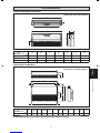
Siesta AHQ100CV1 Guia de instalação
- Categoria
- Condicionadores de ar de sistema split
- Tipo
- Guia de instalação

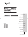
INSTALLATION
MANUAL
Models
AHQ71CV1
AHQ100CV1
AHQ125CV1
AHQ140CV1
IM-5CEY-0711(5)-SIESTA
Part No.: R08019036905E
Installation Manual
Split Type Unit
Manuel D’installation
Type d’unité Split
Installationshandbuch
Split Typ Einheit
Installatiehandleiding
Werdelen Drukletter Eenheid
Manual De Instalación
Escisión tipos Unidades
Руководство по установке
Блок Раздельного Типа
Kurulum kılavuzu
Ayrılma Tipi Üniteleri
Εγχειρίδιο Εγκατάστασης
Διαίρεση Τύπος Μονάδα
Manual De Instalação
Split Tipo Unidades
Manuale D’installazione
Split Tipo di unità
English
Français
Deutsch
Nederlands
Español
Русский
Türkçe
Ελληνικά
Português
Italiano
CVR-IM 5CEY-0711(5)SIESTA-EN.ind1 1CVR-IM 5CEY-0711(5)SIESTA-EN.ind1 1 10/12/17 10:14:02 AM10/12/17 10:14:02 AM


1-1
English
Original Instruction
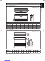
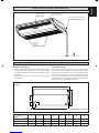
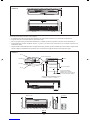
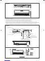
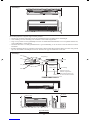
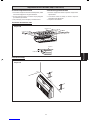
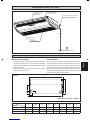
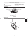
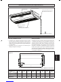
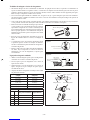
OUTLINE AND DIMENSIONS
Indoor Unit AHQ71/100/125CV1
All dimensions are in mm
A
B
E
C
D
F
G
Indoor Unit AHQ140CV1
D
B
CC
CC
B
A
J
I
G
F
H
L
E
C
K
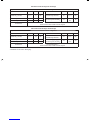
Dimension
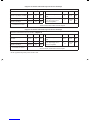
Model ABCDEFG
AHQ71CV1 1272 1088 74 1320 268 635 259
AHQ100CV1 1490 1308 74 1538 268 635 259
AHQ125CV1 1738 1556 74 1786 268 635 259
Dimension
Model ABC D E F G H I J K L
AHQ140CV1 1750 40 36 1903 1830 680 352 292 285 140 1880 250
All dimensions are in mm
Note is valid for Turkey only: The lifetime of our products is ten (10) years
1 IM 5CEY-0711(5)SIESTA-EN.indd 11 IM 5CEY-0711(5)SIESTA-EN.indd 1 10/12/17 9:46:44 AM10/12/17 9:46:44 AM

1-2
SAFETY PRECAUTIONS
! WARNING ! CAUTION
Installation and maintenance should be performed by qualified
persons who are familiar with local code and regulation, and
experienced with this type of appliance.
All field wiring must be installed in accordance with the national
wiring regulation.
Ensure that the rated voltage of the unit corresponds to that of
the name plate before commencing wiring work according to
the wiring diagram.
The unit must be GROUNDED to prevent possible hazard due
to insulation failure.
All electrical wiring must not touch the refrigerant piping, or
any moving parts of the fan motors.
Confirm that the unit has been switched OFF before installing
or servicing the unit.
Disconnect from the main power supply before servicing the
air conditioner unit.
DO NOT pull out the power cord when the power is ON. This
may cause serious electrical shocks which may result in fire
hazards.
Keep the indoor and outdoor units, power cable and transmission
wiring, at least 1m from TVs and radios, to prevent distorted
pictures and static. {Depending on the type and source of the
electrical waves, static may be heard even when more than 1m
away}.
•
•
•
•
•
•
•
•
•
Please take note of the following important points when installing.
Do not install the unit where leakage of flammable gas may occur.
If gas leaks and accumulates around the unit, it may cause
fire ignition.
Ensure that drainage piping is connected properly.
If the drainage piping is not connected properly, it may
cause water leakage which will dampen the furniture.
Do not overcharge the unit.
This unit is factory pre-charged.
Overcharge will cause over-current or damage to the
compressor.
Ensure that the unit’s panel is closed after service or
installation.
Unsecured panels will cause the unit to operate noisily.
Sharp edges and coil surfaces are potential locations which
may cause injury hazards.
Avoid from being in contact with these places.
Before turning off the power supply, set the remote
controller’s ON/OFF switch to the “OFF” position to prevent
the nuisance tripping of the unit. If this is not done, the unit’s
fans will start turning automatically when power resumes, posing
a hazard to service personnel or the user.
Do not operate any heating apparatus too close to the air
conditioner unit. This may cause the plastic panel to melt or
deform as a result of the excessive heat.
Do not install the units at or near doorway.
Do not operate any heating apparatus too close to the air
conditioner unit or use in room where mineral oil, oil vapour
or oil steam exist, this may cause plastic part to melt or
deform as a result of excessive heat or chemical reaction.
When the unit is used in kitchen, keep flour away from going
into suction of the unit.
This unit is not suitable for factory used where cutting oil
mist or iron powder exist or voltage fluctuates greatly.
Do not install the units at area like hot spring or oil refinery
plant where sulphide gas exists.
Ensure the color of wires of the outdoor unit and the terminal
markings are same to the indoors respectively.
IMPORTANT: DO NOT INSTALL OR USE THE AIR
CONDITIONER UNIT IN A LAUNDRY ROOM.
Don’t use joined and twisted wires for incoming power supply.
Avoid direct contact of any coil treatment cleaners on plastic part. This
may cause plastic part to deform as a result of chemical reaction.
For any enquiries on spare parts please contact your
authorized dealer.
The equipment is not intended for use in a potentially
explosive atmosphere.
•
•
•
•
•
•
•
•
•
•
•
•
•
•
•
•
•
•
This manual provides the procedures of installation to ensure a safe and good standard of operation for the air conditioner unit.
Special adjustment may be necessary to suit local requirements.
Before using your air conditioner, please read this instruction manual carefully and keep it for future reference.
This appliance is intended to be used by expert or trained users in shops, in light industry and on farms, or for commercial use by lay persons.
This appliance is not intended for use by persons, including children, with reduced physical, sensory or mental capabilities, or lack of experience
and knowledge, unless they have been given supervision or instruction concerning use of the appliance by a person responsible for their safety.
Children should be supervised to ensure that they do not play with the appliance.
INSTALLATION MANUAL
NOTICE
Disposal requirements
Your air conditioning product is marked with this symbol. This means that electrical and electronic products shall not be mixed with unsorted
household waste.
Do not try to dismantle the system yourself: the dismantling of the air conditioning system, treatment of the refrigerant, of oil and of other
parts must be done by a qualified installer in accordance with relevant local and national legislation.
Air conditioners must be treated at a specialized treatment facility for re-use, recycling and recovery. By ensuring this product is disposed
of correctly, you will help to prevent potential negative consequences for the environment and human health. Please contact the installer or
local authority for more information.
Batteries must be removed from the remote controller and disposed of separately in accordance with relevant local and national legislation.
1 IM 5CEY-0711(5)SIESTA-EN.indd 21 IM 5CEY-0711(5)SIESTA-EN.indd 2 10/12/17 9:46:45 AM10/12/17 9:46:45 AM

1-3
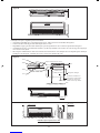
English
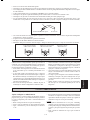
INSTALLATION DIAGRAM (AHQ71/100/125CV1)
Preliminary Site Survey
Voltage supply fluctuation must not exceed ±10% of rated
voltage. Electricity supply lines must be independent
of welding transformer which can cause high supply
fluctuations.
Ensure that the location is convenient for wiring, piping
and drainage.
•
•
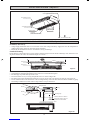
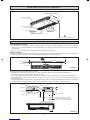
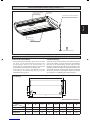
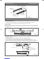
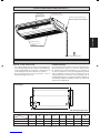
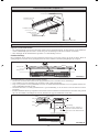
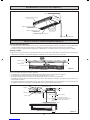
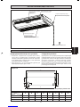
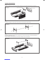
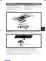
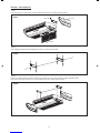
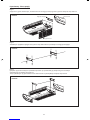
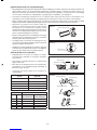
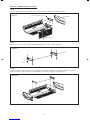
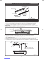
Standard Mounting
Ensure that the overhead supports are strong enough to hold
the weight of the unit. Position the hanger rods (wall mounting
bracket for floor standing), and check for its alignment with
the unit as shown in Figure A. Also, check that the hangers
are secured and the base of the fan coil unit is leveled in both
horizontal directions, taking into account the gradient for
drainage flow as recommended in Figure B.
Figure A
All dimensions are in mm
A
E
B
CD
F
G
H
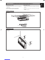
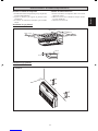
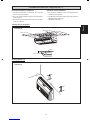
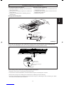
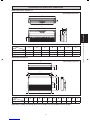
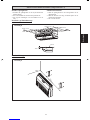
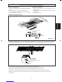
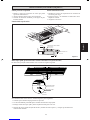
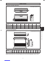
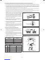
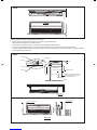
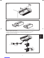
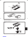
INSTALLATION OF THE INDOOR UNIT (AHQ71/100/125CV1)
TO OUTDOOR UNIT
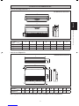
Air Discharge Louver
Signal Receiver
Indicator Light
Air Intake Grille
Wrap the Insulated pipe with the
finishing tape from bottom to top
Air Filters
(Inside Air Intake Grille)
Dimension
Model ABCDEFGH
AHQ71CV1 1320 635 255 134 1222 49 148 120
AHQ100CV1 1538 635 255 134 1440 49 148 120
AHQ125CV1 1786 635 255 134 1688 49 148 120
1 IM 5CEY-0711(5)SIESTA-EN.indd 31 IM 5CEY-0711(5)SIESTA-EN.indd 3 10/12/17 9:46:45 AM10/12/17 9:46:45 AM

1-4
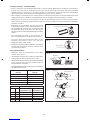
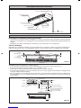
Figure B
10.0mm or less
Please ensure that the following steps are taken:
Unit installation should be tilted at least 10mm as recommended in Figure B.
The drain pipe slope shall be kept at least 1:100.
Provide clearance for easy servicing and optimal air flow as shown in Figure C.
The indoor unit must be installed such that there is no short circuit of the cool discharge air with the warm return air.
Do not install the indoor unit where there is direct sunlight shining on the unit. The location should be suitable for piping
and drainage installation. The unit must be a large distance away from the door.
•
•
•
•
•
10.0mm or more
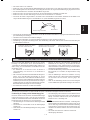
Figure C
1m or more
400mm or more
Floor Standing Type
Utensils, furnitures or built-in
architectural features must not
protrude more than 250mm
Drainage Pipe
250mm or less
300mm
(Min.)
500mm or more
10mm
Indoor Unit
Hanger Bracket
Nut
Washer
Washer
Nut
Floor
2300mm or more
Ceiling
1 IM 5CEY-0711(5)SIESTA-EN.indd 41 IM 5CEY-0711(5)SIESTA-EN.indd 4 10/12/17 9:46:45 AM10/12/17 9:46:45 AM

1-5
English
UNDER CEILING INSTALLATION (AHQ71/100/125CV1)
10mm
300mm or more
300mm or more
635mm
10mm
or more
Ceiling
10mm or more
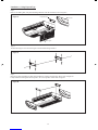
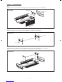
Install Suspension Bolts
Install the suspension bolts so that it can support the
indoor unit.
Adjust distance to ceiling before installation.
Refer to dimension given to install the unit.
1.
2.
3.
Installation Ceiling Type
Installation Floor Type
Wall
Wall
Figure D
Figure E
Install Indoor Units
Insert the suspension bolts into the fi ttings of the hanger
bracket.
Set the nuts and washer on both side of the metal
fi ttings.
Secure it with nuts.
1.
2.
3.
1 IM 5CEY-0711(5)SIESTA-EN.indd 51 IM 5CEY-0711(5)SIESTA-EN.indd 5 10/12/17 9:46:45 AM10/12/17 9:46:45 AM

1-6
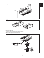
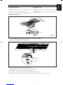
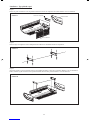
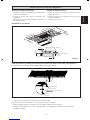
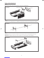
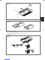
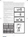
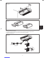
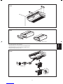
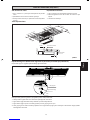
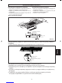
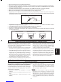
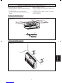
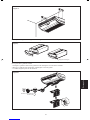
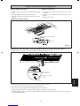
Installation - Ceiling Exposed Type
Step 1
Remove air intake grille, side panel and hanger bracket from the unit. Please refer to Figure F.
Step 2
Position the hanger rod as shown in Figure G and install the hanger bracket.
Figure F
Figure G
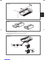
Step 3
Hang up the unit and tighten the bolts after installation of piping and drain pipe. Please refer to Figure H.
Lastly install the intake grille and side panel to the correct position. Please refer to Figure I.
Figure H
Hanger Bracket Side Panel
Intake grille
1 IM 5CEY-0711(5)SIESTA-EN.indd 61 IM 5CEY-0711(5)SIESTA-EN.indd 6 10/12/17 9:46:45 AM10/12/17 9:46:45 AM

1-7
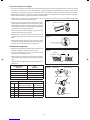
English
Figure I
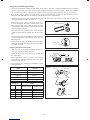
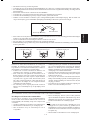
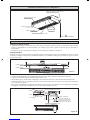
Piping and Drain Hose Installation
Steps to open intake grille
Unlock the screw attached to block lock grille with screwdriver.
Remove block lock grille and unlock grille lock.
Please refer to Figure K for reference.
1.
2.
3.
Block Lock Grille
Screw (M4)
Close
Open
Figure K
Drain Hose
Figure J
1 IM 5CEY-0711(5)SIESTA-EN.indd 71 IM 5CEY-0711(5)SIESTA-EN.indd 7 10/12/17 9:46:45 AM10/12/17 9:46:45 AM

1-8
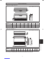
INSTALLATION DIAGRAM (AHQ140CV1)
Air Discharge Louver
Indicator Light
Air Discharge Grille
Air Intake Grille
Signal Receiver
Wrap the Insulated pipe with the
finishing tape from bottom to top
INSTALLATION OF THE INDOOR UNIT (AHQ140CV1)
Preliminary Site Survey
Voltage supply fluctuation must not exceed ±10% of the rated voltage. Electricity supply lines must be independent of
welding transformers which can cause high supply fluctuation.
Ensure that the installation location is convenient for wiring and drainage.
Standard Mounting
Ensure that the overhead supports are strong enough to hold the weight of the unit. Position the hanger rods, and check for its
alignment with the unit. Also, check that the hangers are secured.
•
•
Figure L
10mm
20mm
Ceiling
Unit at level
Unit at level
TO OUTDOOR UNIT
Air Filters
(Inside Air Intake Grille)
Please ensure that the following steps are taken:
Unit installation should be tilted/slanted at least 10mm as recommended in Figure L.
The drain pipe slope shall be kept at least 1:100.
Provide clearance for easy servicing and optimal air flow as shown in Figure M.
The indoor unit must be installed such that there is no short circuit of the cool discharge air with the warm return air.
Do not install the indoor unit where there is direct sunlight shining on the unit. The location should be suitable for piping
and drainage installation. The unit must be a large distance away from the door.
•
•
•
•
•
Figure M
Utensils, furnitures or built-in
architectural features must not
protrude more than 250mm
Drainage Pipe
250mm or less
300mm
(Min.)
500mm or more
10mm
Indoor Unit
Hanger Bracket
Nut
Washer
Washer
Nut
Floor
2300mm or more
Ceiling
1 IM 5CEY-0711(5)SIESTA-EN.indd 81 IM 5CEY-0711(5)SIESTA-EN.indd 8 10/12/17 9:46:46 AM10/12/17 9:46:46 AM

1-9
English
UNDER CEILING INSTALLATION (AHQ140CV1)
Install Suspension Bolts
Install the suspension bolts so that it can support the indoor
unit.
Adjust distance to ceiling before installation.
Refer to dimension given by Figure N to install the unit.
1.
2.
3.
Install Indoor Units
Insert the suspension bolts into the fi tting of the hanger.
bracket.
Set the nuts and washer on both side of the metal fi ttings.
Secure it with nuts.
1.
2.
3.
Installation Ceiling Type
Figure N
10mm or less
Top Panel Of Unit
Ceiling Board
10mm
145-155mm
10mm
300mm or more
10mm
621mm
10mm or less
300mm or more
Cover Lock Grille (The moving part protection for user direct touching)
Cover lock grille must be installed as the figure below.
Intake Grille
Cover Lock Grille
Screw
If the unit need to be service, steps below shall be followed:
Confirm that the unit had been switched off before servicing the unit.
Use screwdriver to unlock the screw on the cover lock grille.
Remove the cover lock grille and open the intake grille for the service purpose.
Install the intake grille and screw the cover lock grille after service and make sure the unit is proper install.
1.
2.
3.
4.
1 IM 5CEY-0711(5)SIESTA-EN.indd 91 IM 5CEY-0711(5)SIESTA-EN.indd 9 10/12/17 9:46:46 AM10/12/17 9:46:46 AM

1-10
D
A
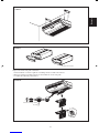
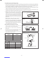
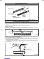
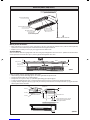
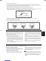
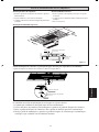
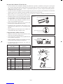
Piping Works And Flaring Technique
Do not use contaminated or damaged copper tubing. If any pipings, evaporator or condenser had been exposed or had been
opened for 15 seconds or more, the system must be vacuumed. Generally, do not remove plastic, rubber plugs and brass
nuts from the valves, fittings, tubings and coils until it is ready to connect suction or liquid line into valves or fittings.
If any brazing work is required, ensure that the nitrogen gas is passed through coil and joints while the brazing work is
being done. This will eliminate soot formation on the inside walls of the copper tubings.
Cut the pipe stage by stage, advancing the blade of the pipe cutter slowly. Extra force and deep cut will cause more distortion
on the pipe and thus extra burr. See Figure I.
•
•
•
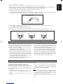
Cutting Copper Tube
Figure II
Figure I
Remove Burr
Figure III
Copper Tube
Swaging Block
Spanner Torque Wrench
Indoor Piping Flare Nut
Flared Tube
Flare Joint
Figure IV
Ø Tube, D A (mm)
Inch mm Imperial
(Wing-nut Type) Rigid
(Clutch Type)
1/4" 6.35 1.3 0.7
3/8" 9.52 1.6 1.0
1/2" 12.70 1.9 1.3
5/8" 15.88 2.2 1.7
3/4" 19.05 2.5 2.0
Pipe Size
(mm/in) Torque
(Nm/ft-lb)
6.35 (1/4") 18 (13.3")
9.52 (3/8") 42 (31.0")
12.70 (1/2") 55 (40.6")
15.88 (5/8") 65 (48.0")
19.05 (3/4") 78 (57.6")
1/4t
Remove burrs from cut edges of the pipes with remover
as shown in Figure II. This will avoid unevenness on the
flare faces which will cause gas leak. Hold the pipe on top
position and burr remover at lower position to prevent metal
chips from entering the pipe.
Insert the flare nuts, mounted on the connection parts
of both the indoor unit and outdoor unit, into the copper
pipes.
The exact length of pipe protruding from the top surface
of the swaging block is determined by the flaring tool.
Refer Figure III.
Fix the pipe firmly on the swaging block. Match the centers
of both the flare die and the flaring punch, and then tighten
the flaring punch fully.
Piping Connection To The Units
Align the center of the piping and tighten the flare nut
sufficiently with fingers. Refer Figure IV.
Finally, tighten the flare nut with the torque wrench until
the wrench clicks.
When tightening the flare nut with the torque wrench,
ensure that the tightening direction follows the arrow
indicated on the wrench.
The refrigerant pipe connection are insulated by closed
cell polyurethane.
•
•
•
•
•
•
•
•
1 IM 5CEY-0711(5)SIESTA-EN.indd 101 IM 5CEY-0711(5)SIESTA-EN.indd 10 10/12/17 9:46:47 AM10/12/17 9:46:47 AM

1-11
English
Attach insulation sleeve
Round crimp-style terminal Electric wire
Connect wires of the
same gauge to both side.
Do not connect wires of the
same gauge to one side.
Do not connect wires
of different gauges.
All wires must be firmly connected.
Make sure all the wire do not touch the refrigerant pipings, compressor or any moving parts.
The connecting wire between the indoor unit and the outdoor unit must be clamped by using provided cord anchorage.
The power supply cord must be equivalent to H07RN-F which is the minimum requirement.
Make sure no external pressure is applied to the terminal connectors and wires.
Make sure all the covers are properly fixed to avoid any gap.
Use round crimp-style terminal for connecting wires to the power supply terminal block. Connect the wires by matching
to the indication on terminal block. (Refer to the wiring diagram attached on the unit).
•
•
•
•
•
•
•
Use the correct screwdriver for terminal screws tightening. Unsuitable screwdrivers can damage the screw head.
Over tightening can damage the terminal screw.
Do not connect wire of different gauge to same terminal.
Keep wiring in an orderly manner. Prevent the wiring from obstructing other parts and the terminal box cover.
•
•
•
•
R410A is a new HFC refrigerant which does not damage the
ozone layer. The working pressure of this new refrigerant is 1.6
times higher than conventional refrigerant (R22), thus proper
installation / servicing is essential.
Never use refrigerant other than R410A in an air conditioner
which designed to operate with R410A.
POE or PVE oil is used as lubricant for R410A compressor,
which is different from the mineral oil used for R22
compressor. During installation or servicing, extra precaution
must be taken not to expose the R410A system too long
to moist air. Residual POE or PVE oil in the piping and
components can absorb moisture from the air.
To prevent mischarging, the diameter of the service port on
the flare valve is different from that of R22.
•
•
•
Use tools and materials exclusively for refrigerant R410A.
Tools exclusively for R410A are manifold valve, charging
hose, pressure gauge, gas leak detector, flare tools, torque
wrench, vacuum pump and refrigerant cylinder.
As an R410A air conditioner incurs higher pressure than R22
units, it is essential to choose the copper pipes correctly.
If the refrigerant gas leakage occurs during installation /
servicing, be sure to ventilate fully. If the refrigerant gas
comes into contact with fire, a poisonous gas may occur.
When installing or removing an air conditioner, do not allow
air or moisture to remain in the refrigerant cycle.
•
•
•
•
SPECIAL PRECAUTIONS WHEN DEALING WITH R410A UNIT
Vacuuming is necessary to eliminate all moisture and air from the system.
Vacuuming The Piping And The Indoor Unit
The indoor unit and the refrigerant connection pipes must
be air-purged because the air containing moisture that
remains in the refrigerant cycle may cause malfunction of
the compressor.
Remove the caps from the valve and the service port.
Connect the center of the charging gauge to the vacuum
pump.
Connect the charging gauge to the service port of the 3-
way valve.
•
•
•
VACUUMING AND CHARGING
Start the vacuum pump. Evacuate for approximately
30 minutes. The evacuation time varies with different
vacuum pump capacity. Confirm that the charging gauge
needle has moved towards -760mmHg.
Caution
If the gauge needle does not move to -760mmHg, be sure to
check for gas leaks (using the refrigerant detector) at flare
type connection of the indoor and outdoor unit and repair
the leak before proceeding to the next step.
Close the valve of the changing gauge and stop the vacuum
pump.
•
•
•
1 IM 5CEY-0711(5)SIESTA-EN.indd 111 IM 5CEY-0711(5)SIESTA-EN.indd 11 10/12/17 9:46:47 AM10/12/17 9:46:47 AM

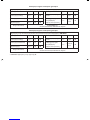
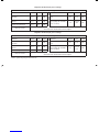
Information requirements for ecodesign
Information to identify the model(s) to which the information relates : AHQ125CV1
Item Symbol Value Unit Item Symbol Value Unit
Cooling capacity (sensible)
Prated, c
9,1 kW Total electric power input
Pelec
0,171 kW
Cooling capacity (latent)
Prated, c
3,0 kW Sound power level (per speed
setting, if applicable)
LWA
65,0/62,0/
60,0 dB
Heating capacity
Prated, h
13,5 kW
Contact details DAIKIN EUROPE N.V.
Zandvoordestraat 300, B-8400 Oostende, Belgium
Information to identify the model(s) to which the information relates : AHQ140CV1
Item Symbol Value Unit Item Symbol Value Unit
Cooling capacity (sensible)
Prated, c
9,6 kW Total electric power input
Pelec
0,316 kW
Cooling capacity (latent)
Prated, c
3,4 kW Sound power level (per speed
setting, if applicable)
LWA
68,0/67,0/
63,0 dB
Heating capacity
Prated, h
15,5 kW
Contact details DAIKIN EUROPE N.V.
Zandvoordestraat 300, B-8400 Oostende, Belgium
*
NOTE : Applicable for EU Market only.
Information requirements for ecodesign
1 IM 5CEY-0711(5)SIESTA-EN.indd 121 IM 5CEY-0711(5)SIESTA-EN.indd 12 10/12/17 9:46:47 AM10/12/17 9:46:47 AM

2-1
Français
Unité Intérieure AHQ71/100/125CV1
Traduction des instructions d’origine
CONTOUR ET DIMENSIONS
Toutes les dimensions sont données en mm
Toutes les dimensions sont données en mm
A
B
E
C
D
F
G
Dimension
Modèle ABCDEFG
AHQ71CV1 1272 1088 74 1320 268 635 259
AHQ100CV1 1490 1308 74 1538 268 635 259
AHQ125CV1 1738 1556 74 1786 268 635 259
Unité Intérieure AHQ140CV1
D
B
CC
CC
B
A
J
I
G
F
H
L
E
C
K
Dimension
Modèle ABC D E F G H I J K L
AHQ140CV1 1750 40 36 1903 1830 680 352 292 285 140 1880 250
Remarque valable pour la Turquie uniquement : La durée de vie de nos produits est de dix (10) ans
2 IM 5CEY-0711(5)SIESTA-FR.indd 12 IM 5CEY-0711(5)SIESTA-FR.indd 1 10/12/17 9:47:39 AM10/12/17 9:47:39 AM

2-2
PRÉCAUTIONS DE SÉCURITÉ
! ATTENTION ! AVERTISSEMENT
L’installation et la maintenance doivent être exécutées par une personne
qualifiée qui est familiarisée avec les lois et réglementations en vigueur,
et aussi expérimentée dans ce type d’équipements.
Tous les câblages doivent répondre aux réglementations électriques
nationales.
Avant de commencer le raccordement suivant le schéma électrique,
s’assurer que la tension nominale de l’appareil corresponde bien à celle
indiquée sur la plaque signalétique.
L’unité doit être raccordée à la TERRE pour prévenir tous les risques
possibles dûes à un défaut d’isolation.
Aucun câble électrique ne doit toucher la tuyauterie du réfrigérant, le
compresseur ou les pièces mobiles des moteurs de ventilation.
Avant l’installation ou l’entretien du climatiseur, s’assurer que l’appareil
est éteint (OFF).
Débrancher l’appareil du circuit d’alimentation secteur avant de procéder
à l’entretien du climatiseur.
NE PAS retirer le câble d’alimentation électrique de la prise quand
l’appareil est sous branché. Il peut en résulter des décharges électriques
importantes susceptibles de provoquer un incendie.
Les unités intérieures et extérieures, le cordon d’alimentation et le câblage
de transmission doivent rester à une distance d’au moins 1m des téléviseurs
et des radios, ce afin d’éviter les images déformées et les parasites.
{En fonction du type et de la source des ondes électriques, des parasites
peuvent être entendus même avec une distance supérieure à 1m}.
•
•
•
•
•
•
•
•
•
Vérifier les points suivants au cours de l’installation.
Ne pas installer l’appareil où il peut se produire des fuites de gaz inflammable.
En cas de fuite et accumulation de gaz autour de l’appareil, il
y a risque d’incendie.
S’assurer que le tuyau d’évacuation du condensat est correctement branché.
Si le tuyau d’évacuation n’est pas correctement branché, les
éventuelles fuites d’eau risquent de mouiller le mobilier.
Ne pas surcharger l’unité (en fluide frigorigène).
Cet appareil est préchargé en usine.
Une charge trop importante risque de provoquer une surcharge
électrique ou d’endommager le compresseur.
S’assurer que le panneau supérieur de l’appareil est remis en
place après l’installation ou l’entretien.
Avec un panneau mal fixé l’appareil va fonctionner bruyamment.
Les bords coupants et les surfaces du refroidisseur tuulaire présentent
un risque de blessure.
Mieux vaut éviter le contact avec ces endroits.
Avant de couper l’alimentation électrique, veiller à ce que l’interrupteur
ON/OFF de la télécommande soit en position « OFF » afin d’éviter
une mise en marche intempestive de l’appareil.Si l’interrupteur de la
télécommande n’est pas en position « OFF », les ventilateurs de l’appareil se
mettront en marche dès que l’alimentation électrique est rétablie. Il peut en
résulter un danger pour le personnel d’entretien ou l’utilisateur.
Ne pas utiliser d’appareil de chauffage trop près du climatiseur. Une
chaleur excessive peut déformer ou faire fondre le boîtier de plastic.
Ne pas installer les appareils à proximité ou près d’un passage de porte.
Ne pas utiliser un appareil de chauffage trop près d’une unité de
climatisation ou l’utiliser dans une pièce où, de l’huile minérale ou de la
vapeur d’huile existent, cela peut faire fondre ou se déformer les pièces en
plastique en raison de la chaleur excessive ou de réaction chimique.
Lorsque l’appareil est utilisé dans la cuisine, le garder loin de la farine
qui peut aller dans d’aspiration de l’appareil.
Cet appareil n’est pas approprié pour une utilisation en usine lorsqu’un
brouillard d’huile de coupe ou de la poudre de fer existe ou bien quand
la tension fluctue grandement.
Ne pas installer les unités à des endroits comme une source d’eau chaude
ou une raffinerie de pétrole où des gaz sulfureux existent.
S’assurer que la couleur des câbles de l’unité extérieure et les marquages
de bornes sont identiques à ceux de l’unité intérieure.
IMPORTANT: NE PAS INSTALLER OU UTILISER LE
CLIMATISEUR DANS UNE BUANDERIE.
N’utilisez pas de câbles joints et torsadés pour l’alimentation électrique
entrante.
Évitez d’appliquer directement des produits de nettoyage et de traitement
pour bobines sur les pièces en plastique. Une réaction chimique pourrait
se produire et déformer les pièces en plastique.
Pour tout renseignement concernant les pièces détachées, contacter votre
revendeur agree.
L’équipement n’est pas destiné à être utilisé dans une atmosphère
potentiellement explosive.
•
•
•
•
•
•
•
•
•
•
•
•
•
•
•
•
•
•
Ce manuel fournit les procédures d’installation pour assurer le bon fonctionnement et la sécurité de cet appareil.
Des ajustements peuvent être nécéssaires pour suivre les réglementations locales.
Avant d’installer et de faire fonctionner le climatiseur, lisez attentivement ce manuel et conservez le.
Cet appareil est destiné à être utilisé par des utilisateurs experts ou formés dans les magasins, dans l’industrie légère ou dans les fermes, oupour un usage
commercial par des personnes non spécialisées.
Cet appareil n’est pas destiné à être utilisé par des personnes, y compris les enfants, souffrant de capacités physiques, sensorielles ou mentales réduites,
ou accusant un manque d’expérience et de connaissances, sauf si elles sont supervisées ou ont reçu des instructions concernant l’emploi de cet appareil
d’une personne responsable de leur sécurité.
Les enfants doivent être supervisés pour s’assurer qu’ils ne jouent pas avec l’appareil.
MANUEL D’INSTALLATION
AVIS
Instructions d’élimination
Cet appareil de conditionnement d’air porte le symbole ci-joint. Ce symbole signifie que les appareils électriques et électroniques doivent être éliminés séparément
des ordures ménagères non triées.
N’essayez pas de démonter vous-même l’appareil : le démontage de l’appareil de conditionnement d’air ainsi que le traitement du réfrigérant, de l’huile et d’autres
composants doivent être effectués par un installateur qualifié, en accord avec les réglementations locales et nationales en vigueur.
Les appareils de conditionnement d’air doivent être traités dans des installations spécialisées de dépannage, réutilisation ou recyclage. En vous assurant que cet
appareil est éliminé correctement, vous contribuez à éviter les conséquences potentiellement néfastes sur l’environnement et la santé. Veuillez contacter votre
installateur ou les autorités locales pour plus d’information.
Les piles de la télécommande doivent être enlevées et éliminées séparément, conformément aux réglementations locales et nationales en vigueur.
2 IM 5CEY-0711(5)SIESTA-FR.indd 22 IM 5CEY-0711(5)SIESTA-FR.indd 2 10/12/17 9:47:39 AM10/12/17 9:47:39 AM

2-3
Français
VERS LʼUNITÉ EXTÉRIEURE
Conduait de ventilation
Voyants du récepteur
de signal
Grilles de reprise d’air
Enveloppez le tuyau isolé de
bande definition de bas en haut
DIAGRAMME D’INSTALLATION (AHQ71/100/125CV1)
Etude Preliminaire Du Site
La fluctuation de l’alimentation secteur ne doit pas dépasser
±10% de la tension nominale. Les lignes d’alimentation
électrique doivent être indépendantes des transformateurs
de soudage qui pourraient provoquer de fortes fluctuations
d’alimentation.
Assurez-vous que l’emplacement est pratique pour les
câblages, la tuyauterie et l’évacuation.
•
•
Montage standard
Vérifier que les supports de plafond sont assez solides pour
supporter le poids de l’appareil. Positionner les tiges de levage
(support de montage mural pour installation au sol) et vérifier
leur alignement avec l’appareil comme illustré dans la Schéma A.
Vérifier également que les supports de suspension sont solidement
ancrés et que la base du ventiloconvecteur est de niveau dans les
deux sens horizontaux, tenant compte de l’inclinaison pour le flux
d’évacuation tel que recommandé dans la Schéma B.
Toutes les dimensions sont données en mm
INSTALLATION DE L’UNITÉ INTÉRIEURE (AHQ71/100/125CV1)
Filltre à air
(Grille d’admission d’air intérieur)
Schéma A A
E
B
C
D
F
G
H
Dimension
Modèle ABCDEFGH
AHQ71CV1 1320 635 255 134 1222 49 148 120
AHQ100CV1 1538 635 255 134 1440 49 148 120
AHQ125CV1 1786 635 255 134 1688 49 148 120
2 IM 5CEY-0711(5)SIESTA-FR.indd 32 IM 5CEY-0711(5)SIESTA-FR.indd 3 10/12/17 9:47:40 AM10/12/17 9:47:40 AM

2-4
Schéma B
S’assurer que les étapes suivantes sont respectées :
L’installation de l’unité devrait être faite inclinée d’au moins 10mm comme il est recommandé à la Schéma B.
La pente du tuyau d’évacuation doit être d’au moins1:100.
Laisser un espace libre pour faciliter la maintenance et obtenir un flux d’air optimal, comme le montre la Schéma C.
L’unité intérieure doit être installé de façon à ce qu’il n’y ait aucun court circuit entre l’air d’évacuation froid et l’air
d’admission chaud.
Ne pas installer l’unité intérieure dans un emplacement où il peut être exposé à la lumière directe du soleil. L’emplacement
doit être adapté à l’installation des tuyauteries et de l’évacuation. L’appareil doit être très éloigné de la porte.
•
•
•
•
•
10,0mm ou moins
10,0mm ou plus
Schéma C
1m ou plus
400mm ou plus
Type sol
Les pièces de mobilier,
d’équipement ou éléments
d’architecture encastrésne doivent
pas s’avancer de plus de 250mm
Tuyau d’évacuation
250mm ou moins
300mm
(Min.)
500mm ou plus
10mm
Unité Intérieure
Ferrure de suspension
Écrou
Rondelle
Rondelle
Écrou
Sol
2300mm ou plus
Plafond
2 IM 5CEY-0711(5)SIESTA-FR.indd 42 IM 5CEY-0711(5)SIESTA-FR.indd 4 10/12/17 9:47:40 AM10/12/17 9:47:40 AM

2-5
Français
INSTALLATION AU PLAFOND (AHQ71/100/125CV1)
10mm
300mm ou plus
300mm ou plus
635mm
10mm
ou plus
Plafond
10mm ou plus
Installer les boulons de suspension
Installer les boulons de suspension pour qu’ils puissant
soutenir l’unité intérieure.
Ajuster la distance par rapport au plafond avant
l’installation.
Se référer aux dimensions indiquées pour installer
l’unité.
1.
2.
3.
Installation de type plafond
Installation Type plancher
Mur
Mur
Schéma D
Schéma E
Installer des unités intérieures
Insérer les boulons de suspension dans le raccord du
support de crochet.
Placer les écrous et les rondelles de chaque côté des
raccords métalliques.
Sécuriser avec les écrous.
1.
2.
3.
2 IM 5CEY-0711(5)SIESTA-FR.indd 52 IM 5CEY-0711(5)SIESTA-FR.indd 5 10/12/17 9:47:40 AM10/12/17 9:47:40 AM

2-6
Installation – Type plafond exposé
Étape 1
Retirez la grille d’admission d’air, le panneau latéral et la ferrure de suspension de l’unité. Référez-vous à la Schéma F.
Étape 2
Placez la tige de suspension comme indiqué dans la Schéma G et installez la ferrure de suspension.
Schéma F
Schéma G
Étape 3
Suspendez l’unité et serrez les boulons après avoir installé la tuyauterie et le tuyau d’évacuation. Référez-vous à la Schéma H.
Enfin, installez la grille d’admission et le panneau latéral dans la bonne position. Référez-vous à la Schéma I.
Schéma H
Ferrure de suspension Panneau latéral
Grille d’admission
2 IM 5CEY-0711(5)SIESTA-FR.indd 62 IM 5CEY-0711(5)SIESTA-FR.indd 6 10/12/17 9:47:40 AM10/12/17 9:47:40 AM
A página está carregando ...
A página está carregando ...
A página está carregando ...
A página está carregando ...
A página está carregando ...
A página está carregando ...
A página está carregando ...
A página está carregando ...
A página está carregando ...
A página está carregando ...
A página está carregando ...
A página está carregando ...
A página está carregando ...
A página está carregando ...
A página está carregando ...
A página está carregando ...
A página está carregando ...
A página está carregando ...
A página está carregando ...
A página está carregando ...
A página está carregando ...
A página está carregando ...
A página está carregando ...
A página está carregando ...
A página está carregando ...
A página está carregando ...
A página está carregando ...
A página está carregando ...
A página está carregando ...
A página está carregando ...
A página está carregando ...
A página está carregando ...
A página está carregando ...
A página está carregando ...
A página está carregando ...
A página está carregando ...
A página está carregando ...
A página está carregando ...
A página está carregando ...
A página está carregando ...
A página está carregando ...
A página está carregando ...
A página está carregando ...
A página está carregando ...
A página está carregando ...
A página está carregando ...
A página está carregando ...
A página está carregando ...
A página está carregando ...
A página está carregando ...
A página está carregando ...
A página está carregando ...
A página está carregando ...
A página está carregando ...
A página está carregando ...
A página está carregando ...
A página está carregando ...
A página está carregando ...
A página está carregando ...
A página está carregando ...
A página está carregando ...
A página está carregando ...
A página está carregando ...
A página está carregando ...
A página está carregando ...
A página está carregando ...
A página está carregando ...
A página está carregando ...
A página está carregando ...
A página está carregando ...
A página está carregando ...
A página está carregando ...
A página está carregando ...
A página está carregando ...
A página está carregando ...
A página está carregando ...
A página está carregando ...
A página está carregando ...
A página está carregando ...
A página está carregando ...
A página está carregando ...
A página está carregando ...
A página está carregando ...
A página está carregando ...
A página está carregando ...
A página está carregando ...
A página está carregando ...
A página está carregando ...
A página está carregando ...
A página está carregando ...
A página está carregando ...
A página está carregando ...
A página está carregando ...
A página está carregando ...
A página está carregando ...
A página está carregando ...
A página está carregando ...
A página está carregando ...
A página está carregando ...
A página está carregando ...
A página está carregando ...
A página está carregando ...
A página está carregando ...
A página está carregando ...
-
 1
1
-
 2
2
-
 3
3
-
 4
4
-
 5
5
-
 6
6
-
 7
7
-
 8
8
-
 9
9
-
 10
10
-
 11
11
-
 12
12
-
 13
13
-
 14
14
-
 15
15
-
 16
16
-
 17
17
-
 18
18
-
 19
19
-
 20
20
-
 21
21
-
 22
22
-
 23
23
-
 24
24
-
 25
25
-
 26
26
-
 27
27
-
 28
28
-
 29
29
-
 30
30
-
 31
31
-
 32
32
-
 33
33
-
 34
34
-
 35
35
-
 36
36
-
 37
37
-
 38
38
-
 39
39
-
 40
40
-
 41
41
-
 42
42
-
 43
43
-
 44
44
-
 45
45
-
 46
46
-
 47
47
-
 48
48
-
 49
49
-
 50
50
-
 51
51
-
 52
52
-
 53
53
-
 54
54
-
 55
55
-
 56
56
-
 57
57
-
 58
58
-
 59
59
-
 60
60
-
 61
61
-
 62
62
-
 63
63
-
 64
64
-
 65
65
-
 66
66
-
 67
67
-
 68
68
-
 69
69
-
 70
70
-
 71
71
-
 72
72
-
 73
73
-
 74
74
-
 75
75
-
 76
76
-
 77
77
-
 78
78
-
 79
79
-
 80
80
-
 81
81
-
 82
82
-
 83
83
-
 84
84
-
 85
85
-
 86
86
-
 87
87
-
 88
88
-
 89
89
-
 90
90
-
 91
91
-
 92
92
-
 93
93
-
 94
94
-
 95
95
-
 96
96
-
 97
97
-
 98
98
-
 99
99
-
 100
100
-
 101
101
-
 102
102
-
 103
103
-
 104
104
-
 105
105
-
 106
106
-
 107
107
-
 108
108
-
 109
109
-
 110
110
-
 111
111
-
 112
112
-
 113
113
-
 114
114
-
 115
115
-
 116
116
-
 117
117
-
 118
118
-
 119
119
-
 120
120
-
 121
121
-
 122
122
-
 123
123
-
 124
124


Siesta AHQ100CV1 Guia de instalação
- Categoria
- Condicionadores de ar de sistema split
- Tipo
- Guia de instalação
em outros idiomas
- español: Siesta AHQ100CV1 Guía de instalación
- français: Siesta AHQ100CV1 Guide d'installation
- italiano: Siesta AHQ100CV1 Guida d'installazione
- Nederlands: Siesta AHQ100CV1 Installatie gids
- Deutsch: Siesta AHQ100CV1 Installationsanleitung
- Türkçe: Siesta AHQ100CV1 Yükleme Rehberi
Outros documentos
-
Electrolux EXC650EIWA24 Guia de instalação
-
Sanyo SPW-XR254EH56 Manual do usuário
-
Chariot Carriers Merci Guia de instalação
-
LG URNU36GVKA2 Manual do usuário
-
Mitsubishi Electric PLFY-P-VAM-E Guia de instalação
-
LG ARNU48GV2A4 Guia de instalação
-
HTW CONJUNTO SUELO TECHO TWIN ADMIRA Manual do usuário
-
mundoclima MUCSR-H8 Manual do proprietário
-
Infiniton SSCHD48A2 Manual do proprietário
-
 Kaysun Ducts 4P Manual do usuário
