
Istruzioni ed avvertenze per l’installazione e l’uso
Instructions and warnings for installation and use
Instrucciones y advertencias para su instalación y uso
Anleitungen und Hinweise zu Installation und Einsatz
Instruções e advertências para a instalação e utilização
Instructions et avertissements pour l’installation et l’usage
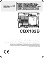
CBX102B
Control unit for a 230 Vac motor, for a sliding gate or up-and-over door
Steuergerät für einen Motor 230 Vac, für Schiebetor oder Schwingtor
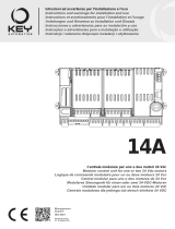
Centrale per un motore 230 Vac, per cancello scorrevole o portone basculante
Logique de commande pour un moteur 230 Vca, pour portail coulissant ou porte basculante
Central para un motor 230 Vca, para puerta de corredera o portón basculante
Unidade para um motor 230 Vac, para portão de correr ou portão basculante
Centrala do silnika 230 Vac, napędzającego przesuwną bramę ogrodzeniową
lub uchylną bramę garażow
Motoriduttore interrato
Under grounded gear motor
Motoreducteur enterré
Motorreductor interrado
Unrterflur-Drehtorantrieb
Motorredutor interrado
Podziemny motoreduktor
UNDER
Istruzioni ed avvertenze per l’installazione e l’uso
Instructions and warnings for installation and use
Instrucciones y advertencias para su instalación y uso
Anleitungen und Hinweise zu Installation und Einsatz
Instruções e advertências para a instalação e utilização
Instructions et avertissements pour l’installation et l’usage
Management
System
ISO 9001:2008
www.tuv.com
ID 9105043769

2
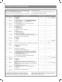
EN
1
2
3
4
5
6
7
8
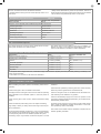
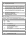
Safety warnings
2.1
2.2
2.3
2.4
4.1
4.2
4.3
4.4
4.5
5.1
5.2
Product Introduction
Description of the control unit
Description of the connections
Models and technical characteristics
List of cables required
Preliminary Checks
Installing the Product
Electric connections
Display during normal operation
Autolearning of the travel stroke
Customising the system - BASIC MENU
Connecting the radio receiver
Testing and commissioning
Testing
Commissioning
Further details - ADVANCED MENU
Instructions and warnings for the
nal user
EC declaration of conformity
pag. 3
pag. 4
pag. 4
pag. 4
pag. 4
pag. 5
pag. 5
pag. 6
pag. 6
pag. 7
pag. 8
pag. 9
pag. 10
pag. 10
pag. 10
pag. 10
pag. 11
pag. 12
pag. 79
TABLE OF CONTENTS

3
EN
ORIGINAL INSTRUCTIONS - important safety instructions.
Compliance with the safety instructions below is important for
personal safety. Save these instructions.
Read the instructions carefully before proceeding with installation.
The design and manufacture of the devices making up the
product and the information in this manual are compliant with
current safety standards. However, incorrect installation or
programming may cause serious injury to those working on or
using the system. Compliance with the instructions provided
here when installing the product is therefore extremely impor-
tant.
If in any doubt regarding installation, do not proceed and contact the
Marantec Technical Service for clarications.
Under European legislation, an automatic door or gate system
must comply with the standards envisaged in the Directive
2006/42/EC (Machinery Directive) and in particular standards
EN 12453; EN 12635 and EN 13241-1, which enable declaration
of presumed conformity of the automation system.
Therefore, nal connection of the automation system to the electri-
cal mains, system testing, commissioning and routine maintenance
must be performed by skilled, qualied personnel, in observance of
the instructions in the “Testing and commissioning the automation
system” section.
The aforesaid personnel are also responsible for the tests required
to verify the solutions adopted according to the risks present, and for
ensuring observance of all legal provisions, standards and regula-
tions, with particular reference to all requirements of the EN12453
standard which establishes the test methods for testing door and
gate automation systems.
Before starting installation, perform the following checks and
assessments:
ensure that every device used to set up the automation system is
suited to the intended system overall. For this purpose, pay special
attention to the data provided in the “Technical specications” sec-
tion. Do not proceed with installation if any one of these devices is
not suitable for its intended purpose;
check that the devices purchased are sucient to guarantee system
safety and functionality;
perform a risk assessment, including a list of the essential safety
requirements as envisaged in Annex I of the Machinery Directive,
specifying the solutions adopted. The risk assessment is one of the
documents included in the automation system’s technical le. This
must be compiled by a professional installer.
Considering the risk situations that may arise during instal-
lation phases and use of the product, the automation system
must be installed in compliance with the following safety pre-
cautions:
never make modications to any part of the automation system other
than those specied in this manual. Operations of this type can only
lead to malfunctions. The manufacturer declines all liability for da-
mage caused by unauthorised modications to products;
if the power cable is damaged, it must be replaced by the manufac-
turer or its after-sales service, or in all cases by a person with similar
qualications, to prevent all risks;
do not allow parts of the automation system to be immersed in water
or other liquids. During installation ensure that no liquids are able to
enter the various devices;
should this occur, disconnect the power supply immediately and
contact a Marantec Service Centre. Use of the automation system in
these conditions may cause hazards;
never place automation system components near to sources of heat
or expose them to naked lights. This may damage system compo-
nents and cause malfunctions, re or hazards;
all operations requiring opening of the protective housings of various
automation system components must be performed with the control
unit disconnected from the power supply. If the disconnect device is
not in a visible location, ax a notice stating: “MAINTENANCE IN
PROGRESS”:
connect all devices to an electric power line equipped with an
earthing system;
the product cannot be considered to provide eective protection
against intrusion. If eective protection is required, the automation
system must be combined with other devices;
the product may not be used until the automation system “commis-
sioning” procedure has been performed as specied in the “Automa-
tion system testing and commissioning” section;
the system power supply line must include a circuit breaker device
with a contact gap allowing complete disconnection in the conditions
specied by class III overvoltage;
use unions with IP55 or higher protection when connecting hoses,
pipes or cable glands;
the electrical system upstream of the automation system must com-
ply with the relevant regulations and be constructed to good wor-
kmanship standards;
users are advised to install an emergency stop button close to the
automation system (connected to the control PCB STOP input) to
allow the door to be stopped immediately in case of danger;
this device is not intended for use by persons (including children)
with impaired physical, sensory or mental capacities, or with lack
of experience or skill, unless a person responsible for their safety
provides surveillance or instruction in use of the device;
before starting the automation system, ensure that there is no-one
in the immediate vicinity;
before proceeding with any cleaning or maintenance work on the
automation system, disconnect it from the electrical mains;
special care must be taken to avoid crushing between the part ope-
rated by the automation system and any xed parts around it;
children must be supervised to ensure that they do not play with the
equipment.
The automation system component packaging material must
be disposed of in full observance of current local waste dispo-
sal legislation.
The automation system component packaging material must
be disposed of in full observance of current local waste dispo-
sal legislation.
Marantec reserves the right to amend these instructions if ne-
cessary; they and/or any more recent versions are available at
www.marantec.com
1 - SAFETY WARNINGS
ATTENTION !
ATTENTION !
ATTENTION !
ATTENTION !

4
EN
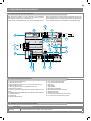
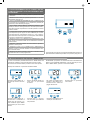
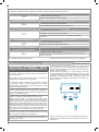
The CBX102B control unit is the most modern, ecient system for
the control of Marantec motors for the electric opening and closure
of sliding gates and up-and-over doors.
All other, improper, use of the control unit is forbidden. The CBX102B
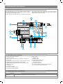
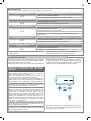
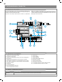
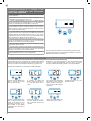
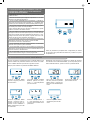
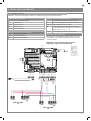
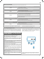
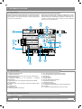
1- Motor power supply connections
2- Capacitor connector
3- 230 Vac (120 Vac) power supply connections to ashing and
courtesy lights
4- 24 Vdc power supply connection to controls and safety devices
5- RED EDGE-PH2-PH1-STOP safety warning LEDs
6- GREEN OPEN-CLOSE-PAR-SBS command indicator LEDs
7- Antenna connector
8- LCD display
9- Limit switch connector
10- Limit switch indicator LED LS1
11- Limit switch indicator LED LS2
12- UP + button
13- MENU button
14- DOWN - button
15- STEP BY STEP SBS button
16- Safety device dip switch
17- Transformer primary
18- Transformer secondary
19- F2- 500 mA rapid fuse protecting the accessories
20- F1- 6.3 A rapid fuse protecting the line
has a display allowing easy programming and constant monitoring
of the input status; the menu structure also allows easy setting of
working times and operating modes.
2.1 - Description of the control unit
2.2 - Description of the connections
CODICE DESCRIZIONE
CBX102B 230 V control unit for sliding gates or up-and-over doors
2.3 - Models and technical characteristics
2 - INTRODUCING THE PRODUCT
SHIELD
FUSE 2
FUSE 1
UP
MENU
SBS
DOWN
ANT
LS1
LS2
COM
PH-POW
EDGE
PH 2
EDGE
PH 1
N
L
COM Vac
CR
FLASH
+ 24 Vdc
NEG
STOP
OPEN
CLOSE
SBS
PAR
COM
COM
COND
MOTOR
L1
L2
EDGE
EDGE
PH2
PH1
STOP
OPEN
PAR
SBS
CLOSE
PH2
PH1
STOP
10
12
15
13
14
11
5
6
9
8
18
19
4
16
17
3
1
2
7
7
20

5
EN
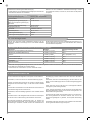
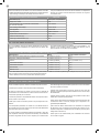
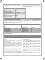
ELECTRIC CABLE TECHNICAL SPECIFICATIONS:
Connection cable maximum allowable limit
Control unit power supply line 1 x cable 3 x 1,5 mm
2
20 m *
Flashing light, courtesy light
Antenna
1 x cable 4 x 0,5 mm
2
**
1 x cable type RG58
20 m
20 m (advised < 5 m)
Transmitter photocells 1 x cable 2 x 0,5 mm
2
20 m
Receiver photocells 1 x cable 4 x 0,5 mm
2
20 m
Sensitive edge 1 x cable 2 x 0,5 mm
2
20 m
Key-switch 1 x cable 4 x 0,5 mm
2
20 m
TECHNICAL SPECIFICATIONS CBX102B
Power supply (L-N) 230 Vac (+10% - 15%) 50-60 Hz
Max motor load 700 W
Output for Vdc accessories power and device test power 24 Vdc 500 mA
Courtesy light output 230 Vac 100 W
Flashing light output 230 Vac 40 W
Pause time Adjustable 0-900 sec.
Operating temperature -20 °C + 55 °C
Accessory fuses (F2) 500mAF
Power supply line fuses (F1) 6,3AF
3 - PRELIMINARY CHECKS
The cables required for connection of the various devices in a stan-
dard system are listed in the cables list table.
Before installing the product, perform the following checks and in-
spections:
check that the gate or door is suitable for automation;
the weight and size of the gate or door must be within the operating
limits specied for the automation system in which the product is
installed;
check that the gate or door has rm, eective mechanical safety
stops;
make sure that the product xing zone is not subject to ooding;
high acidity or salinity or nearby heat sources might cause the pro-
duct to malfunction;
in case of extreme weather conditions (e.g. snow, ice, wide tempera-
ture variations or high temperatures), friction may increase, causing
a corresponding rise in the force needed to operate the system;
the starting torque may therefore exceed that required in normal
conditions;
check that when operated by hand the gate or door moves smoothly
without any areas of greater friction or derailment risk;
check that the gate or door is well balanced and will therefore re-
main stationery when released in any position;
check that the electricity supply line to which the product is to be
connected is suitably earthed and protected by an overload and dif-
ferential safety breaker device;
the system power supply line must include a circuit breaker device
with a contact gap allowing complete disconnection in the condi-
tions specied by class III overvoltage;
ensure that all the material used for installation complies with the
relevant regulatory standards.
The cables used must be suitable for the type of installation; for
example, an H03VV-F type cable is recommended for indoor appli-
cations, while H07RN-F is suitable for outdoor applications.
- Power supply with protection against short-circuits inside the con-
trol unit, on motors and on the connected accessories.
- Obstacle detection during travel at normal speed by means of cur-
rent sensor.
- Automatic learning of working times.
- Safety device deactivation by means of dip switches: there is no
need to bridge the terminals of safety devices which are not installed
- the function is simply disabled by means of a dip switch.
* If the power cable is longer than 30 m, a cable with a larger cross-section is required (3x2.5 mm
2
) and safety earthing is necessary in the
vicinity of the automation.
** Two cables of 2 x 0.5 mm
2
can be used as an alternative
2.4 - List of cables required

6
EN
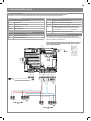
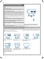
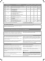
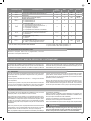
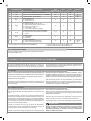
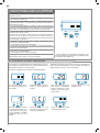
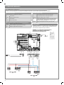
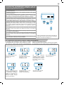
MOTOR CONNECTOR
Power supply connection terminal board
L1 Motor live
COM Motor common
L2 Motor live
COND Motor capacitor
MOTOR LIMIT SWITCH CONNECTION
LS1 Limit switch 1 input
COM Limit switch common
LS2 Limit switch 2 input
POWER SUPPLY CONNECTOR
L Power supply live 230 Vac (120 Vac) 50-60 Hz
N Power supply neutral 230 Vac (120 Vac) 50-60 Hz
COM Vac
Common of the “CR” and “FLASH” outputs
CR Courtesy light, 230 Vac (120 Vac) 100 W, output
controllable also via radio ON-OFF command (radio
channel 4 selecting fC.y. = 2, tC.y. = 0 )
FLASH Flashing light, 230 Vac (120 Vac) 40 W
DIP SWITCH
Set on “ON” to disable inputs EDGE, PH2, PH1, STOP.
Eliminates the need to bridge the terminal board inputs.
WARNING - with the dip switch ON, the safety
devices are disabled
WARNING - Before making the connections, ensure that the control unit is not powered up.
OUTPUT
24 Vdc
2
3
4
1
1
2
TX
RX
NC
PH2
2
3
4
1
1
2
TX
RX
PH1
N
L
GND
_
12/24
AC/DC
GND
_
12/24
AC/DC
COM
OUT
GND
_
12/24
AC/DC
GND
_
12/24
AC/DC
COM
OUT
NC
SHIELD
FUSE 2
FUSE 1
UP
MENU
SBS
DOWN
ANT
LS1
LS2
COM
PH-POW
EDGE
PH 2
EDGE
PH 1
N
L
COM Vac
CR
FLASH
+ 24 Vdc
NEG
STOP
OPEN
CLOSE
SBS
COM
PAR
COMMON
STEP BY STEP
PARTIAL
CLOSE
OPEN
STOP
PHOTOCELL 1
PHOTOCELL 2
EDGE
EDGE
PHOTOTEST
NEGATIVE
COM
COND
MOTOR
L1
L2
EDGE
EDGE
PH2
PH1
STOP
OPEN
CLOSE
PAR
SBS
PH2
PH1
STOP
4 - PRODUCT INSTALLATION
4.1 - Electrical connections

7
EN
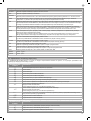
SAFETY AND CONTROL DEVICE CONNECTOR
+24 Vdc Accessories power supply positive 24 Vdc, 250 mA
NEG Accessories power supply negative
PH-POW
Photocells PH1 and PH2 power supply positive; phototest can be selected with parameter tph 24 Vdc, 250 mA
EDGE Safety sensor edge, ON/OFF NC contact or resistive 8K2 between EDGE and EDGE (warning, with dip switch 1 ON the
safety EDGE input is o)
PH2 Photocells (opening), NC contact between PH2 and COM (warning, with dip switch 2 ON the PHOTOCELL 2 safety device
input is o) The photocell is tripped at any time during opening of the automation system, halting operation immediately;
the automation system will continue opening when the contact is restored.
PH1 Photocells (closing), NC contact between PH1 and COM (warning, with dip switch 3 ON the PHOTOCELL 1 safety device
input is o) The photocell is tripped at any time during closing of the automation system, halting operation immediately and
reversing the travel direction
STOP STOP safety device, NC contact between STOP and COM (warning, with dip switch 4 ON the STOP safety device input is
o)
This input is classied as a safety device; the contact can be deactivated at any time, cutting out the automation system
and disabling all functions, including Automatic Closure
OPEN OPEN command NO contact between OPEN and COM
Contact for the HOLD-TO-RUN function. The gate OPENS as long as the contact is held down
CLOSE CLOSE command NO contact between CLOSE and COM
Contact for the HOLD-TO-RUN function. The gate CLOSES as long as the contact is held down
PAR PARTIAL command NO contact between PAR and COM
Used to open the gate partially, depending on the software setting
SBS STEPPING command NO contact between SBS and COM
Open/Stop/Close/Stop command, or as set in the software
COM Common for the PH1, PH2, STOP, OPEN, CLOSE, PAR and SBS inputs
SIGNAL Antenna - signal -
SHIELD Antenna - shield -
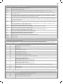
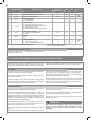
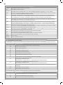
MESSAGES MEANING
-.-
Limit switch CLOSING (one dot between the two lines)
tC.
Limit switch OPENING (a point to the right)
SO
No limit switch active (no dots present)
In addition, the dots between the gures illustrate the status of the limit switches, as described in greater detail below:
MESSAGES MEANING
--
Gate closed or switch-on after shutdown
OP
Gate opening
CL
Gate closing
SO
Gate stopped during opening
SC
Gate stopped during closure
HA
Gate stopped by external event
oP
Gate stopped without automatic reclosure
Pe
Gate in partial opening position without automatic reclosure
-tC
Gate open with timed reclosure
Flashing dash counting in progress
Dash replaced by gures 0..9 countdown (last 10s)
-tP
Gate in partial opening position with timed reclosure
Flashing dash counting in progress
Dash replaced by gures 0..9 countdown (last 10s)
L--
Learning started on limit switch (move the gate o the limit switch to continue the learning procedure)
LOP
Learning opening
LCL
Learning closure
4.2 - Display during normal operation
In “NORMAL OPERATING MODE”, i.e. when the system is powered up normally, the 3-gure LCD display shows the following status messages:

EN
8
SURGE OVERLOAD ALARM The motor’s current drawdown has increased very quickly
EFO
1. The gate has struck an obstacle.
2. Friction on runners or rack.
SAFETY EDGE ALARM The control unit has received a signal from the safety edge
EED
1. The safety edge has been pressed.
2. The safety edge is not connected correctly.
LIMIT SWITCH ALARM The limit switches are not working properly
ELS
1. The limit switches are damaged.
2. The limit switches are not connected.
3. Check the travel time which has passed without tripping of the limit switches.
PHOTOCELL ALARM Phototest fail outcome.
EPH
1. Check the photocell connections.
2. Check that the photocells are operating correctly.
ELECTRONIC OVERLOAD CUTOUT
TRIPPED
Motor not absorbing power
Eth
1. Check the motor’s power drawdown.
2. Check that the gate travels smoothly and that there are no obstacles.
Malfunctions
This section lists a number of malfunctions which may occur.
After eliminating the cause of the alarm, to delete all errors simply
press the “DOWN -” key or press the SBS (STEP BY STEP)
command
The display returns to the normal screen.
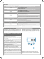
The rst time the control unit is powered up, an autolearning proce-
dure must be carried out to acquire fundamental parameters such as
the travel stroke length and deceleration points.
Press the + or - keys to view not only the status of the control unit, as
explained in the rst table in point 4.2, but also the count of the ope-
ning-closing operations performed. In the operation count display,
thousands, displayed without dots, alternate with units, displayed
with dots between them (e.g.: 50.000 = 50/0.0.0)
AUTOLEARNING OF THE TRAVEL STROKE AND
MAIN PARAMETERS, WITH PRESET DECELERA-
TIONS
The decelerations will be those set in the menu, with the same
percentage during both opening and closing.
To program the decelerations in manual mode, move straight on
to the next table.
1. Release the gate or door, move it onto the central position and
lock it in place again. For customised programming of decelera-
tions, move on to the next section.
2. Hold down the + and MENU buttons SIMULTANEOUSLY for
more than 5 seconds, until the screen shows LOP and get ready to
press the DOWN key (see illustration) if necessary.
3. If the rst operation is NOT opening of the gate, press the
DOWN key to stop the autolearning.
Then press SBS to restart the acquisition: the gate starts moving
again, in the right direction. The motor opens the gate at low speed
to the opening limit switch (if the torque is not sucient
to move the gate, delete the decelerations from the menu [LSI=0]).
When the open limit switch is reached, the gate sets o again in
the closing direction at full speed, displaying LCL.
4. Wait for two complete operating cycles (2 opening and 2 closing
strokes) to be completed and for the gate to nish travel in the
closed position (displaying --).
5. Perform a number of opening, closing and sudden stop com-
mands to ensure that the system is solid with no assembly defects.
All the main parameters are set with the default settings by the
control unit. To customise the installation, proceed as described in
point 4.4 below.
UP
SBS
DOWN
MENU
4.3 - Autolearning of the travel stroke

9
EN
All the main parameters are set with the default settings by the
control unit. To customise the installation, proceed as described in
point 4.4 below.
AUTOLEARNING OF THE TRAVEL STROKE AND
MAIN PARAMETERS, WITH CUSTOMISED DECELE-
RATIONS
1. Release the gate or door, move it onto the central position and
lock it in place again.
2. Access the basic menu to set parameter LSI=P as shown in the
table in point 4.4.
3. Hold down the + and MENU buttons SIMULTANEOUSLY for
more than 5 seconds, until the screen shows LOP and get ready to
press the DOWN key (see illustration) if necessary.
4. If the rst operation is NOT opening of the gate, press the
DOWN key to stop the autolearning.
Then press SBS to restart the acquisition: the gate starts moving
again, in the right direction.
5. The motor opens the gate at low speed to the opening limit
switch (if the torque is not sucient
to move the gate, delete the decelerations from the menu [LSI=0]).
When the open limit switch is reached, the gate sets o again in
the closing direction at full speed, displaying LCL.
6. When the gate reaches the point where you wish closing dece-
leration to start, give an SBS command.
The gate will continue to travel at low speed.
7. When the limit switch is reached, the gate will start to open at
full speed.
8. When the gate reaches the point where you wish opening dece-
leration to start, give an SBS command.
The gate will continue to travel at low speed.
9. When the open limit switch is reached, the gate will close auto-
matically, preforming the programmed travel stroke.
UP DOWN
MENU
SBS
UP
UP
UP
UP
UP UP
UP
DOWN
DOWN
DOWN
DOWN
DOWN DOWN
DOWN
MENU
MENU
MENU
MENU
MENU MENU
MENU
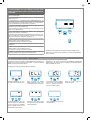
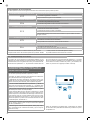
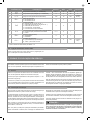
After accessing the BASIC
MENU, press the + and – keys
to scroll through the functions.
Press the MENU key quickly to
quit the menu.
Press the MENU key for 1 se-
cond to access the basic menu.
Press the + and – keys to scroll
through the functions to modify
other parameters.
Press the + and – keys to to
modify the value.
Press the MENU key for 1 se-
cond to display the parameter
in order to save the modied
value, or MENU quickly to quit
the function without saving.
To access the value modica-
tion function, press the MENU
key for 1 second, until the va-
lue starts to ash quickly.
Exampling of modifying a BASIC MENU parameter
If necessary, users may select a BASIC MENU which allows modi-
cation of the control unit’s basic parameters. To select the BASIC
MENU proceed as described below.
WARNING: to be certain of accessing the NORMAL OPERATION
display state, the starting point for accessing the BASIC MENU,
press the MENU key twice
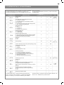
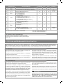
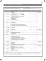
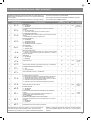
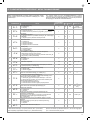
4.4 - Customising the system - BASIC MENU

EN
10
PARAMETERS DESCRIPTION
DEFAULT
CONFIGURATION
MIN MAX UNIT
1
TCL
Automatic reclosure time (0 = o) 20 *** 0 900 s
2
ttr
Reclosing time after transit (0 = o) 0 0 30 s
3
trq**
Motor force (peak torque) 100 10 100
% (step
of 10)
4
SSL**
Deceleration mode
0 = 1/3 deceleration
1 = 2/3 deceleration
0 0 1
5
SbS
SBS conguration:
0 = Normal (AP-ST-CH-ST-AP-ST…)
1 = Alternate STOP (AP-ST-CH-AP-ST-CH…)
2 = Alternate (AP-CH-AP-CH…)
3 = Apartment block – timer
4 = Apartment block with immediate reclosure
0 0 4
6
blt
Post blackout procedure
0 = no action, remains stationery
1 = Closure
0 **** 0 1
7
SST**
Soft start
0 = o
1 = on
0 0 1
8
LSI**
Deceleration distance
P = customised by learning
0…100% = percentage of travel stroke
15 * 0 100
% (step
of 1)
** for 120V version parameter NOT PRESENT *** for 120V version default value = 15
**** for 120V version default value = 1
4.5 Connecting the radio receiver
Connect the radio receiver, for programming follow the receiver
DIGITAL 992 instructions
All system components must be tested following the procedures de-
scribed in their respective operator’s manuals;
ensure that the recommendations in Chapter 1 - Safety Warnings -
have been complied with;
check that the gate or door is able to move freely once the automa-
tion system has been released and is well balanced, meaning that it
will remain stationery when released in any position;
check that all connected devices (photocells, sensitive edges, emer-
gency buttons, etc.) are operating correctly by performing gate or
door opening, closing and stop tests using the connected control
devices (transmitters, buttons or switches);
perform the impact measurements as required by the EN12453
standard, adjusting the control unit’s speed, motor force and dece-
leration functions if the measurements do not give the required re-
sults, until the correct setting is obtained.
5.1 Testing
5 - TESTING AND COMMISSIONING THE AUTOMATION SYSTEM
The system must be tested by a qualied technician, who must per-
form the tests required by the relevant standards in relation to the
risks present, to check that the installation complies with the relevant
regulatory requirements, especially the EN12453 standard which
species the test methods for gate and door automation systems.
ATTENTION !
5.2 Commissioning
Once all (and not just some) of the system devices have passed the
testing procedure, the system can be commissioned;
the system’s technical dossier must be produced and kept for 10
years. It must contain the electrical wiring diagram, a drawing or
photograph of the system, the analysis of the risks and the solutions
adopted to deal with them, the manufacturer’s declaration of con-
formity for all connected devices, the operator’s manual for every
device and the system maintenance plan;
x a dataplate with the details of the automation, the name of the
person who commissioned it, the serial number and year of con-
struction and the CE marking on the gate or door;
also t a sign specifying the procedure for releasing the system by
hand;
draw up the declaration of conformity, the instructions and precau-
tions for use for the end user and the system maintenance plan and
consign them to the end user;
ensure that the user has fully understood how to operate the system
in automatic, manual and emergency modes;
the end user must also be informed in writing about any risks and
hazards still present;
After detecting an obstacle, the gate or door stops during its
opening travel and automatic closure is disabled; to restart
operation, the user must press the control button or use the
transmitter.

11
EN
PARAMETERS DESCRIPTION
DEFAULT
CONFIGURATION
MIN MAX UNIT
1
EL.F.
Electric brake
0 = o
1 = on
0 0 100
x 0.01s
(step of 5)
2
SP.h.
Use of PHOTO1 when starting from closed
0 = PHOTO1 is checked
1 = The gate starts even with PHOTO1 excited
1 0 1
3
Ph.2.
Use of PHOTO2
0 = Enabled during both opening and closing AP/CH
1 =Only enabled during opening AP
0 0 1
4
tP.h.
Photo-device test
0 = o
1 = PHOTO1 on
2 = PHOTO2 on
3 = PHOTO1 and PHOTO2 on
0 0 3
5
Ed.m.
Sensitive edge type
0 = contact (NC)
1 = resistive (8k2)
0 0 1
6
iE.D.
Sensitive edge tripping mode
0= only tripped during closure with direction reversal
1 = stops the automation (during both opening and
closure) and retreats from the obstacle
0 0 1
7
tE.D.
Edge test
0 = o
1 = on
0 0 1
8
LP.o.
Partial opening 30 0 100
%
(step of 1)
9
TP.C.
Time for automatic closure from partial opening (0=o) 20 0 900 s
10
FP.r.
Flashing light output setup
0 = Steady
1 = Flashing
1 0 1
11
tP.r.
Pre-ashing time (0 = o) 0 0 10 s
12
FC.Y.
Courtesy light setup
0 = On at end of operation for time TCY
1 = On if gate not closed + duration of TCY
2 = On if courtesy light timer (TCY) time not out
3 = Gate open light on/o
4 = Gate open light proportional ashing
0 0 4
13
tC.Y.
Courtesy light on time 0 0 900
s
(step of 10s)
14
de.a.
Hold-to-run
0 = o
1 = on
0 0 1
15
se.r.
Service interval cycle threshold. Once the set
threshold is reached, the light ashes
at high speed in all subsequent cycles (only if FPR is
on).
(0 = o)
0 0 100
x 1000
cycles
16
se.f.
Enabling of continuous ashing indicating
service required (only active with gate closed).
0 = o
1 = on
0 0 1
17
de.f.
Restoring the default values
The ADVANCED MENU allows the system to be further customised
by modifying parameters not accessible from the basic menu
To access the ADVANCED menu, press the MENU key and hold it
To set the default values: 1) access the advanced programming
function; 2) select the “dEf” parameter”; 3) activate the modication
mode (“0” on display”); 4) accept the modication (press “MENU”
down for 5 seconds
To modify ADVANCED MENU parameters, proceed as described for
the BASIC MENU
and hold it down). A countdown should now appear: d80,d79...,d01
down to “don“. Release the key when nished.
6 - FURTHER DETAILS - ADVANCED MENU

12
EN
Marantec Antriebs- und Steuerungstechnik GmbH & Co. KG produ-
ces systems for the automation of gates, garage doors, automatic
doors, roller blinds and car-park and road barriers. However, Ma-
rantec is not the manufacturer of your complete automation system,
which is the outcome of the analysis, assessment, choice of mate-
rials and installation work of your chosen installer. Every automation
system is unique, and only your installer has the experience and
skill required to produce a safe, reliable, durable system tailored to
your needs, and above all that complies with the relevant regulatory
standards. Although your automation system complies with the re-
gulation safety level, this does not rule out the presence of “residual
risk”, meaning the possibility that hazards may occur, usually due to
reckless or even incorrect use. We would therefore like to give you
some advice for the correct use of the system:
• before using the automation system for the rst time, have the in-
staller explain the potential causes of residual risks to you;
• keep the manual for future reference, and pass it on to any new
owner of the automation system;
• reckless use and misuse of the automation system may make it
dangerous: do not operate the automation system with people, ani-
mal or objects within its range of action;
• a properly designed automation system has a high level of safety,
since its sensor systems prevent it from moving with people or ob-
stacles present so that its operation is always predictable and safe.
However, as a precaution children should not be allowed to play clo-
se to the automation system, and to prevent involuntary activation,
remote controls must not be left within their reach;
• as soon as any system malfunction is noticed, disconnect the elec-
tricity supply and perform the manual release procedure. Never at-
tempt repairs on your own; call in your installation engineer. In the
meantime the door or gate can be operated without automation once
the geared motor has been released using the release key supplied
with the system. In the event of safety devices out of service arrange
for repairs to the automation immediately;
• in the event of malfunctions or power failures: while waiting for the
engineer to come (or for the power to be restored if your system is
not equipped with buer batteries), the door or gate can be used just
like any non-automated installation. To do this, the manual release
procedure must be carried out;
• manual release and operation: rst bear in mind that the release
procedure can only be carried out with the door or gate stationery.
• Maintenance: Like any machine, your automation system needs
regular periodic maintenance to ensure its long life and total safety.
Arrange a periodic maintenance schedule with your installation en-
gineer. Marantec recommends that maintenance checks should be
carried out every six months for normal domestic use, but this inter-
val may vary depending on the level of use. Any inspection, main-
tenance or repair work must only be carried out by qualied sta.
• Never modify the automation system or its programming and setup
parameters: this is the responsibility of your installation engineer.
• Testing, routine maintenance and any repairs must be recorded by
the person who performs them and the documents must be conser-
ved by the system’s owner.
The only procedures you are capable of, and which you are recom-
mended to perform, are cleaning of the photocell glass and removal
of any leaves or stones that may obstruct the automation system.
To prevent anyone from activating the gate or door, release the au-
tomation system before starting. Clean only with a cloth dipped in a
little water.
At the end of its useful life, the automation system must be disman-
tled by qualied personnel, and the materials must be recycled or
disposed of in compliance with the legislation locally in force.
If after some time your remote control seems to have become less
eective, or stops operating completely, the battery may be at (de-
pending on the level of use, this may take from several months up
to more than a year). You will realise this because the transmission
conrmation light does not come on, or only lights up for a very short
time.
Batteries contain pollutants: do not dispose of them with normal wa-
ste but follow the methods specied by the local regulations.
Thank you for choosing Marantec Antriebs- und Steuerungstechnik
GmbH & Co. KG; please visit our Internet site www.marantec.com
for further information.
7 - INSTRUCTIONS AND WARNINGS FOR THE END USER

13
DE
1
2
3
4
Sicherheitshinweise
2.1
2.2
2.3
2.4
4.1
4.2
4.3
4.4
4.5
Einführung in das Produkt
Beschreibung des Steuergerätes
Beschreibung der Anschlüsse
Modelle und technische Eigenschaften
Liste benötigter Kabel
Vorabkontrollen
Produktinstallation
Elektrische Anschlüsse
Anzeige Normalmodus
Einlernen des Laufs
Benutzerdenierte Einrichtung der Anlage -
GRUNDMENÜ
Anschluss des Funkempfängers
S. 14
S. 15
S. 15
S. 15
S. 15
S. 16
S. 16
S. 17
S. 17
S. 18
S. 19
S. 20
S. 21
5
6
5.1
5.2
Test und Inbetriebnahme
Abnahme
Inbetriebnahme
Vertiefung - ERWEITERTES MENÜ
S. 21
S. 21
S. 21
S. 22
7
Anweisungen und Hinweise für
den Endbenutzer
S. 23
8
EG-Konformitätserklärung S. 79
INHALTSVERZEICHNIS

14
DE
ORIGINALANWEISUNGEN – Wichtige Sicherheitsanweisun-
gen. Für die Sicherheit der Personen ist es wichtig, die folgen-
den Sicherheitsanweisungen zu befolgen. Bewahren Sie diese
Anweisungen auf.
Vor Durchführung der Installation lesen Sie die Anleitung bitte
aufmerksam durch.
Die Konstruktion und die Herstellung der Geräte, aus denen
sich das Produkt zusammensetzt, und die in diesem Handbuch
enthaltenen Informationen entsprechen den geltenden Si-
cherheitsvorschriften. Dennoch können eine falsche Installa-
tion und eine falsche Programmierung schwerwiegende Ver-
letzungen bei Personen verursachen, die die Arbeit ausführen,
und bei denen, die die Anlage benutzen werden. Aus diesem
Grund ist es wichtig, während der Installation strikt alle Anwei-
sungen in diesem Handbuch zu beachten.
Bei Zweifel jeglicher Art die Installation abbrechen und ggf. den Ma-
rantec Kundendienst zur Klärung kontaktieren.
Für die europäische Gesetzgebung muss der Einbau einer au-
tomatischen Tür oder eines automatischen Tors den Bestim-
mungen der Richtlinie 2006/42/EG (Maschinenrichtlinie) und im
Besonderen den Normen EN 12453, EN 12635 und EN 13241-1
entsprechen, die eine Konformitätserklärung der Automatisie-
rung ermöglichen.
In Anbetracht dessen müssen die endgültige Verbindung der Auto-
matisierung ans Stromnetz, die Endabnahme der Anlage, die Inbe-
triebnahme und die regelmäßige Wartung von qualiziertem und
erfahrenem Personal entsprechend den Anleitungen unter „Prüfung
und Inbetriebnahme der Automatisierung“ durchgeführt werden.
Außerdem muss das Personal auch die vorgesehenen Tests nach
den vorhandenen Risiken festlegen und die Einhaltung der Gesetze,
Vorschriften und Regeln überprüfen: insbesondere die Einhaltung
der Norm EN12453, welche die Prüfverfahren für die Automatisie-
rung von Türen und Toren festlegt.
Vor Installationsbeginn folgende Analysen und Prüfungen dur-
chführen:
Sicherstellen, dass die für die Automatisierung vorgesehenen
Vorrichtungen für die zu realisierende Anlage geeignet sind. Die-
sbezüglich aufmerksam die im Kapitel „Technische Eigenschaften“
aufgeführten Daten prüfen. Die Installation nicht durchführen, wenn
auch nur eine der Vorrichtungen nicht für den Gebrauch geeignet ist.
Sicherstellen, dass die erworbenen Vorrichtungen ausreichend sind,
um die Sicherheit und Funktion der Anlage zu gewährleisten.
Die Risikoanalyse durchführen, welche auch die Liste der Si-
cherheitsanforderungen, aufgeführt in Anhang I der Maschinenricht-
linie, beinhalten muss, und die angewandten Lösungen nennen.Die
Risikoanalyse ist eine der Unterlagen, aus denen sich die techni-
schen Unterlagen der Automatisierung zusammensetzen. Diese
müssen von einem erfahrenen Installateur ausgefüllt werden.
In Anbetracht der Gefahrensituationen, die bei Installation und
Benutzung des Produktes auftreten können, muss die Automa-
tisierung unter Berücksichtigung folgender Hinweise installiert
werden:
Keine Änderungen an der Automatisierung vornehmen, wenn diese
nicht in diesem Handbuch vorgesehen sind. Diese können nur zu
Funktionsstörungen führen. Der Hersteller übernimmt keine Haftung
für Schäden, die durch eigenmächtige Änderungen am Produkt ve-
rursacht wurden.
Ist das Stromkabel beschädigt, muss es vom Hersteller, seinem
technischen Kundendienst oder einer ähnlich qualizierten Person
ersetzt werden, um Gefährdungen zu vermeiden;
Die einzelnen Komponenten der Automatisierung dürfen nicht in
Wasser oder andere Flüssigkeiten getaucht werden. Bei der In-
stallation darauf achten, dass keine Flüssigkeit ins Innere der Vor-
richtungen dringt.
Sollten Flüssigkeiten ins Innere der Automatisierungskomponenten
dringen, sofort die Stromzufuhr abschalten und sich an den Maran-
tec Kundendienst wenden. Die Benutzung der Automatisierung in
derartigen Situationen kann gefährlich sein.
Die einzelnen Komponenten weder Wärmequellen noch oenen
Flammen aussetzen. Dadurch können Schäden, Störungen und
Gefahrensituationen entstehen oder ein Brand ausbrechen.
Alle Arbeiten, die ein Önen der Schutzhülle der Komponenten er-
fordern, müssen bei abgeschalteter Stromzufuhr durchgeführt wer-
den. Sollte die Abschaltvorrichtung nicht sichtbar sein, ein Schild mit
der Aufschrift „IN WARTUNG“ anbringen.
Alle Vorrichtungen müssen mit einer Stromleitung verbunden wer-
den, die sicher geerdet ist.
Dieses Produkt kann nicht als ausreichendes System für den
Einbruchsschutz angesehen werden. Wenn Sie sich ausreichend
schützen wollen, müssen andere Vorrichtungen in die Automatisie-
rung integriert werden.
Wie im Absatz „Prüfung und Inbetriebnahme der Automatisierung“
vorgesehen, darf das Produkt erst nach der „Inbetriebnahme“ der
Automatisierung benutzt werden.
Im Stromnetz der Anlage eine Abschaltvorrichtung mit ausreichen-
dem Önungsabstand der Kontakte vorsehen, die, wie von der Über-
spannungskategorie III gefordert, die komplette Abschaltung erlaubt.
Verwenden Sie für die Verbindung von steifen und exiblen Rohren oder
Kabeldurchgängen Anschlüsse mit dem Schutzgrad IP55 oder höher.
Die elektrische Anlage vor der Automatisierung muss den geltenden
Bestimmungen entsprechen und fachgerecht ausgeführt sein.
Angeraten ist ein Notschalter, der in der Nähe der Automatisierung
angebracht wird (verbunden mit dem Eingang STOP der Steuerpla-
tine), so dass ein sofortiges Anhalten bei Gefahr möglich ist.
Diese Vorrichtung eignet sich nicht für Personen (einschließlich
Kinder) mit eingeschränkten körperlichen, geistigen oder Sin-
nesfähigkeiten, oder denen die nötige Erfahrung oder die Kennt-
nisse fehlen, es sei denn, sie werden von einer für ihre Sicherheit
verantwortlichen Person begleitet oder beaufsichtigt oder in der Be-
nutzung der Vorrichtung unterwiesen.
Vergewissern Sie sich vor der Inbetriebsetzung der Automatisie-
rung, dass sich keine Personen in unmittelbarer Nähe benden;
Vor jeder Reinigung und Wartung ist die Automatisierung vom
Stromnetz zu trennen;
Besondere Vorsicht ist geboten, um Quetschungen zwischen dem
geführten Teil und festen Elementen in der unmittelbaren Nähe zu
vermeiden;
Kinder sollten beaufsichtigt werden, um sicherzustellen, dass sie
nicht mit dem Gerät spielen.
Das Verpackungsmaterial aller Automatisierungskomponenten
muss entsprechend den örtlichen Bestimmungen entsorgt wer-
den.
Das Verpackungsmaterial aller Automatisierungskomponen-
ten muss entsprechend den örtlichen Bestimmungen entsorgt
werden. Marantec behält sich vor, diese Anweisungen notfalls zu
ändern; diese Anweisungen und/oder eine neuere Version benden
sich auf der Website www.marantec.com
1 - SICHERHEITSHINWEISE
ACHTUNG !
ACHTUNG !
ACHTUNG !
ACHTUNG !

15
DE
Das Steuergerät CBX102 ist das modernste und ezienteste
Steuersystem für Motoren von Marantec zum elektrischen Önen
und Schließen von Schiebe- und Schwingtoren.
Jeder andere unsachgemäße Gebrauch des Steuergerätes ist ver-
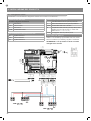
1- Versorgungsanschlüsse Motor
2- Verbinder Kondensator
3- Versorgungsanschlüsse 230 Vac (120 Vac) Blinkleuchten und
zusätzliche Be leuchtung
4- Versorgungsanschluss 24 Vdc Bedienelemente und
Sicherheitsvorrichtungen
5- ROTE Signal-LEDs Sicherheitsvorrichtungen EDGE-PH2-PH1-
STOP
6- GRÜNE Signal-LEDs Bedienelemente OPEN-CLOSE-PAR-SBS
7- Verbinder Antenne
8- LCD-Display
9- Verbinder Endanschlag
10- LS1 LED-Anzeige Endschalter
11- LS2 LED-Anzeige Endschalter
12- Taste UP +
13- Taste MENU
14- Taste DOWN -
15- Taste SBS Schrittbetrieb
16- Dip Switch Sicherheitsvorrichtungen
17- Haupttransformator
18- Nebentransformator
19- F2- Sicherung Zubehörschutz 500 mA ink
20- F1- Sicherung Leitungsschutz 6,3 A ink
boten. Das CBX102 ist mit einem Display ausgestattet, das eine ein-
fache Programmierung und kontinuierliche Überwachung des Sta-
tus der Eingänge erlaubt. Außerdem gewährleistet der Menüaufbau
eine einfache Einstellung der Arbeitszeiten und der Betriebslogik.
2.1 - Beschreibung des Steuergerätes
2.2 - Beschreibung der Anschlüsse
CODE BESCHREIBUNG
CBX102B 230-V-Steuergerät für einen Schiebe- oder Schwingtormotor
2.3 - Modelle und technische Eigenschaften
2 - EINFÜHRUNG IN DAS PRODUKT
SHIELD
FUSE 2
FUSE 1
UP
MENU
SBS
DOWN
ANT
LS1
LS2
COM
PH-POW
EDGE
PH 2
EDGE
PH 1
N
L
COM Vac
CR
FLASH
+ 24 Vdc
NEG
STOP
OPEN
CLOSE
SBS
PAR
COM
COM
COND
MOTOR
L1
L2
EDGE
EDGE
PH2
PH1
STOP
OPEN
PAR
SBS
CLOSE
PH2
PH1
STOP
10
12
15
13
14
11
5
6
9
8
18
19
4
16
17
3
1
2
7
7
20

16
DE
TECHNISCHE SPEZIFIKATIONEN FÜR ELEKTRISCHE KABEL:
Anschluss kabelliste maximal zulässige Grenze
Elektrische Versorgungsleitung der Steuerung 1 x kabel 3 x 1,5 mm
2
20 m *
Blinkleuchte, zusätzliche Beleuchtung
Antenne
1 x kabel 4 x 0,5 mm
2
**
1 x kabel typ RG58
20 m
20 m (empfohlen < 5 m)
Lichtschranke Sender 1 x kabel 2 x 0,5 mm
2
20 m
Lichtschranke Empfänger 1 x kabel 4 x 0,5 mm
2
20 m
Schaltleiste 1 x kabel 2 x 0,5 mm
2
20 m
Schlussenschalter 1 x kabel 4 x 0,5 mm
2
20 m
TECHNISCHE MERKMALE CBX102B
Spannungsversorgung (L-N) 230 Vac (+10% - 15%) 50-60 Hz
Motorhöchstlast 700 W
Ausgang Spannungsversorgung Zu-
behör Vdc und Spannungsversorgung
Gerätetest
24 Vdc 500 mA
Ausgang zusätzliche Beleuchtung 230 Vac 100 W
Ausgang Blinkleuchte 230 Vac 40 W
Pausenzeit Einstellbar 0-900 sec.
Betriebstemperatur -20 °C + 55 °C
Sicherungen Zubehör (F2) 500mAF
Sicherungen Versorgungsleitung (F1) 6,3AF
3 - VORABKONTROLLEN
Die bei einer typischen Anlage erforderlichen Kabel für den An-
schluss der einzelnen Vorrichtungen sind in der Tabelle Kabelliste
aufgeführt.
Vor der Installation bitte folgende Punkte prüfen und kontrollieren:
kontrollieren, ob sich Tor oder Tür für die Automatisierung eignen;
gewicht und Größe des Tors oder der Tür müssen innerhalb der Ein-
satzgrenzen der Automation liegen, auf der das Produkt installiert
wird;
kontrolle des Vorhandenseins und der Stärke der mechanischen Si-
cherheitsanschläge des Tors oder der Tür;
sicherstellen, dass der Befestigungsbereich nicht überutet werden
kann;
überhöhter Säure- oder Salzgehalt oder die Nähe von Wärmequel-
len können eine Funktionsstörung des Produktes verursachen;
bei extremen klimatischen Verhältnissen (wie z. B. Schnee, Eis,
hohe Temperaturunterschiede, hohe Temperaturen) könnten sich
die Reibungen verstärken; deshalb könnte der Kraftaufwand für
die Bewegung und das Anlaufmoment höher sein als im Normalzu-
stand;
kontrollieren, dass die manuelle Bewegung des Tors oder der Tür
üssig und ohne Reibungspunkte ist und keine Entgleisungsgefahr
besteht;
prüfen, dass sich das Tor oder die Tür im Gleichgewicht bendet
und folglich in jeder Stellung stillsteht;
prüfen, dass die Stromleitung für den Anschluss des Produkts über
eine Sicherheitserdung verfügt und mit einem Leitungsschutz- und
Dierentialschalter geschützt ist;
im Stromnetz der Anlage eine Abschaltvorrichtung mit ausreichen-
dem Önungsabstand der Kontakte vorsehen, die, wie von der
Überspannungskategorie III gefordert, die komplette Abschaltung
erlaubt;
sicherstellen, dass das gesamte für die Installation benutzte Mate-
rial den geltenden Bestimmungen entspricht.
Die benutzten Kabel müssen dem Installationstyp entsprechen; z. B.
wird ein Kabel des Typs H03VV-F für Innenbereiche bzw. H07RN-F
für Außenbereiche empfohlen.
- Gegen Kurzschlüsse im Steuergerät, an den Motoren und am an-
geschlossenen Zubehör geschützte Versorgung.
- Hinderniserkennung bei Betriebsgeschwindigkeit per Stromsensor.
- Automatisches Erlernen der Arbeitszeit.
- Ausschaltung der Sicherheitseingänge durch Dip Switch: Die
Klemmen der nicht installierten Sicherheitsvorrichtungen müssen
nicht überbrückt werden; es reicht aus, die Funktion mit Dip Switch
zu sperren.
* Wenn das Versorgungskabel länger als 30 ist, muss ein Kabel mit größerem Querschnitt benutzt (3x2,5 mm
2
) und eine Sicherheitserdung
in der Nähe der Automatisierung installiert werden.
** Alternativ können zwei Kabel 2 x 0,5 mm
2
verwendet werden.
2.4 - Liste benötigter Kabel

17
DE
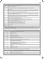
MOTORVERBINDER
Klemmenleiste Versorgungsanschlüsse
L1 Phase Motor
COM Gemeinsamer Leiter Motor
L2 Phase Motor
COND Motorkondensator
MOTOR ENDSCHALTERBELEGUNG
LS1 Eingang Endschalter 1
COM Gemeinsamer Endschalter
LS2 Eingang Endschalter 2
STROMVERBINDER
L Phase 230 Vac (120 Vac) 50-60 Hz
N Nullleiter 230 Vac (120 Vac) 50-60 Hz
COM Vac Gemeinsamer Leiter der Ausgänge „CR“ und „FLASH“
CR Zusätzliche Beleuchtung, 230 Vac (120 Vac) 100
W, Ausgang Bedienung auch per Funk ON-OFF (4.
Funkkanal dazu fC.y. = 2, tC.y. = 0 auswählen)
FLASH Blinkleuchte, 230 Vac (120 Vac) 40 W
WÄHLSCHALTER DIP SWITCH
Bei Einstellung auf „ON“ sperrt er die Eingänge EDGE, PH2,
PH1, STOP. Dadurch entfällt die Notwendigkeit, die Eingänge auf
der Klemmenleiste zu überbrücken.
ACHTUNG - Bei Einstellung des Dip Switch auf ON
sind die angeschlossenen Sicherheitsvorrichtun-
gen ausgeschlossen.
ACHTUNG - Vor dem Anschluss sicherstellen, dass die Stromzufuhr des Steuergerätes abgeschaltet ist.
OUTPUT
24 Vdc
2
3
4
1
1
2
TX
RX
NC
PH2
2
3
4
1
1
2
TX
RX
PH1
N
L
GND
_
12/24
AC/DC
GND
_
12/24
AC/DC
COM
OUT
GND
_
12/24
AC/DC
GND
_
12/24
AC/DC
COM
OUT
NC
SHIELD
FUSE 2
FUSE 1
UP
MENU
SBS
DOWN
ANT
LS1
LS2
COM
PH-POW
EDGE
PH 2
EDGE
PH 1
N
L
COM Vac
CR
FLASH
+ 24 Vdc
NEG
STOP
OPEN
CLOSE
SBS
COM
PAR
COMMON
STEP BY STEP
PARTIAL
CLOSE
OPEN
STOP
PHOTOCELL 1
PHOTOCELL 2
EDGE
EDGE
PHOTOTEST
NEGATIVE
COM
COND
MOTOR
L1
L2
EDGE
EDGE
PH2
PH1
STOP
OPEN
CLOSE
PAR
SBS
PH2
PH1
STOP
4 - PRODUKTINSTALLATION
4.1 - Stromanschlüsse

18
DE
VERBINDER FÜR SICHERHEITSVORRICHTUNGEN UND BEDIENELEMENTE
+24 VDC Spannungsversorgung Zubehör positiv 24 VDC, 250 mA
NEG Spannungsversorgung Zubehör negativ
PH-POW
Positive Spannungsversorgung der Fotozellen PH1, PH2; Fototest wählbar über Parameter tph 24 VDC, 250 mA
EDGE Sicherheitsleiste, ON/OFF NC-Kontakt oder Widerstandsleiste 8K2 zwischen EDGE und EDGE (Achtung: bei Dip Switch
1 auf ON wird der Eingang der Sicherheitsvorrichtung LEISTE gesperrt).
PH2 Fotozellen (Önung) NC-Kontakt zwischen PH2 und COM (Achtung: bei Dip Switch 2 auf ON wird der Eingang der
Sicherheitsvorrichtung FOTOZELLE 2 gesperrt). Die Fotozelle spricht zu jedem Zeitpunkt während der Önung der Au-
tomation an und bewirkt die sofortige Blockierung der Bewegung; bei Wiederherstellung des Kontaktes wird die Önung
fortgesetzt.
PH1 Fotozellen (Schließung) NC-Kontakt zwischen PH1 und COM (Achtung: bei Dip Switch 3 auf ON wird der Eingang der
Sicherheitsvorrichtung FOTOZELLE 1 gesperrt). Die Fotozelle spricht zu jedem Zeitpunkt während der Schließung der
Automation an und bewirkt die sofortige Blockierung der Bewegung mit Umkehr der Laufrichtung.
STOP STOP Sicherheitsvorrichtung NC-Kontakt zwischen STOP und COM (Achtung: bei Dip Switch 4 auf ON wird der Sicherungsein-
gang STOP gesperrt). Dieser Eingang wird als Sicherheitsvorrichtung angesehen; der Kontakt kann jederzeit abgeschaltet
werden, sodass die Automation sofort angehalten und jede Funktion, auch die automatische Schließung, deaktiviert wird.
OPEN Befehl ÖFFNEN NO-Kontakt zwischen OPEN und COM
Kontakt TOTMANN- Funktion. Das Tor ÖFFNET, solange der Kontakt gedrückt wird.
CLOSE Befehl SCHLIESSEN NO-Kontakt zwischen CLOSE und COM
Kontakt TOTMANN- Funktion. Das Tor SCHLIEßT, solange der Kontakt gedrückt wird.
PAR Betätigung der TEILÖFFNUNG NO-Kontakt zwischen PAR und COM
Befehl zur teilweisen Önung der Tür, mit Software einstellbar.
SBS Befehl SCHRITTBETRIEB NO-Kontakt zwischen SBS und COM
Befehl Önen/Stopp/Schließen/Stopp oder je nach Softwareeinstellung.
COM Gemeinsamer Leiter für Eingänge PH1, PH2, STOP, OPEN, CLOSE, PAR, SBS
SIGNAL Antenne - Signal -
SHIELD Antenne - Schutzgeecht -
ANZEIGEN BEDEUTUNG
--
Tor geschlossen oder Neustart nach Ausschalten
OP
Tor in Önung
CL
Tor in Schließung
SO
Tor in Önung angehalten
SC
Tor in Schließung angehalten
HA
Tor durch Fremdeingri angehalten
oP
Tor ohne automatisches Wiederschließen angehalten
Pe
Tor in Position Teilönung ohne automatisches Wiederschließen
-tC
Tor geönet mit zeitgesteuertem Wiederschließen
Blinkender Strich Zeitkontrolle läuft
Strich durch Zahl 0..9 ersetzt Rückwärtszählen zum Start (letzte 10 s)
-tP
Tor teilgeönet mit zeitgesteuertem Wiederschließen
Blinkender Strich Zeitkontrolle läuft
Strich durch Zahl 0..9 ersetzt Rückwärtszählen zum Start (letzte 10 s)
L--
Einlernen am Endanschlag gestartet (das Tor vom Endanschlag wegbewegen, um den Einlernvorgang fortzusetzen)
LOP
Einlernen bei Önung
LCL
Einlernen bei Schließung
ANZEIGEN BEDEUTUNG
-.-
Endanschlag SCHLIESSEN (zwischen den zwei Ziern ist ein Linien)
tC.
Endanschlag ÖFFNUNGS (ein Punkt auf der rechten Seite)
SO
Kein Endanschlag eingeschaltet (kein Punkt vorhanden)
Zusätzlich zeigen die Punkte zwischen den unten genannten Ziern den Endschalterstatus wie folgt an:
4.2 - Anzeige Normalmodus
Im „NORMALMODUS“, d. h. bei normaler Stromspeisung des Systems, zeigt das LCD-Display mit 3 Ziern folgende Statusmeldungen:

19
DE
ALARM IMPULSÜBERLAST Der Strom des Motors ist sehr schnell gestiegen
EFO
1. Das Tor ist auf ein Hindernis gestoßen.
2. An der Laufschiene oder Zahnstange sind Reibungen vorhanden.
ALARM SICHERHEITSLEISTE Das Steuergerät hat ein Signal der Sicherheitsleiste erfasst
EED
1. Die Sicherheitsleiste wird gedrückt.
2. Die Sicherheitsleiste ist nicht sachgerecht angeschlossen.
ALARM ENDANSCHLAG Die Endanschläge funktionieren nicht sachgemäß
ELS
1. Die Endanschläge sind beschädigt.
2. Die Endanschläge sind nicht angeschlossen.
3. Prüfen, wie lange das Tor bewegt wurde, ohne dass die Endanschläge bean-
sprucht wurden
ALARM LICHTSCHRANKE Der Fototest hat ein negatives Ergebnis erbracht
EPH
1. Die Anschlüsse der Lichtschranke kontrollieren.
2. Die korrekte Funktionsweise der Lichtschranke überprüfen.
ANSPRECHEN DES ELEKTRONISCHEN
THERMOSCHUTZES
Keine Stromaufnahme des Motors
Eth
1. Die Aufnahme des Motors überprüfen.
2. Den üssigen und hindernisfreien Lauf kontrollieren.
Betriebsstörungen
In diesem Absatz werden einige Betriebsstörungen aufgelistet, die auftreten können.
Nach Aufhebung des Alarms zum Löschen aller Fehlermeldungen
die Taste „DOWN -“
oder das Bedienelement SBS (SCHRITTBETRIEB) drücken.
Das Display kehrt wieder zur normalen Anzeige zurück.
Bei der ersten Stromversorgung des Steuergeräts muss ein Einlernvor-
gang durchgeführt werden, der die Ermittlung grundlegender Parameter
wie Lauänge und Verlangsamungen erlaubt.
Drückt man die Tasten + oder -, kann man neben dem Steuergerätestatus
(siehe erste Tabelle des Absatzes 4.2) auch die Anzahl der durchgeführ-
ten Bewegungen ablesen. Bei der Bewegungsanzeige werden abwe-
chselnd die Tausenderwerte, angezeigt ohne Punkte, und die Einheiten,
unterteilt durch Punkte, angezeigt (Beispiel: 50.000 = 50/0.0.0).
EINLERNEN DES LAUFS UND DER HAUPTPARA-
METER MIT VOREINGESTELLTEN VERLANGSA-
MUNGEN
Die Verlangsamungen werden entsprechend der Einstellung im
Menü durchgeführt werden, wobei der Prozentwert sowohl beim
Önen als auch beim Schließen gleich ist.
Soll auch die Verlangsamung manuell programmiert werden, fah-
ren Sie bitte direkt mit der nachfolgenden Tabelle fort.
1. Das Tor oder die Tür entriegeln, in mittlere Stellung bringen und
wieder anhalten. Soll auch die Verlangsamung benutzerdeniert pro-
grammiert werden, fahren Sie bitte mit dem nachfolgenden Absatz fort.
2. GLEICHZEITIG die Tasten + und MENU mehr als 5 Sekun-
den drücken, bis LOP angezeigt wird, und sich zum Drücken (falls
nötig) der Taste DOWN bereithalten (siehe Abbildung).
3. Wenn die erste Bewegung KEINE Önung ist, die Taste DOWN
drücken, um den Einlernvorgang zu stoppen. Dann SBS drücken,
damit der Lernvorgang wieder startet: Das Tor setzt sich in die
richtige Richtung in Bewegung. Der Motor önet mit geringer
Geschwindigkeit bis zum Erreichen des Endanschlags für die
Önung (sollte das Kraftmoment nicht ausreichen, um das Tor zu
bewegen, die Verlangsamungen vom Menü entfernen [LSI=0]).
Bei Erreichen des Endschalters für die Önung setzt sich das Tor
wieder mit voller Geschwindigkeit in Schließrichtung in Bewe-
gung, wobei LCL angezeigt wird.
4. Abwarten, dass zwei Bewegungen komplett durchgeführt wur-
den (2 Önungen und 2 Schließungen) und dass das Tor den Lauf
mit der Schließung beendet (Anzeige --).
5. Einige Önungs-, Schließbewegungen und plötzliche Stopps
durchführen, um sicherzustellen, dass das System verlässlich ist
und keine Montagefehler vorliegen.
Alle wichtigen Parameter werden standardmäßig vom Steuergerät
konguriert. Zur benutzerdenierten Einrichtung der Installation mit
dem nächsten Absatz 4.4 fortfahren.
UP
SBS
DOWN
MENU
4.3 - Einlernen des Laufs

20
DE
UP
UP
UP
UP
UP UP
UP
DOWN
DOWN
DOWN
DOWN
DOWN DOWN
DOWN
MENU
MENU
MENU
MENU
MENU MENU
MENU
Zum Scrollen der Funktio-
nen die Tasten + und – im
GRUNDMENÜ drücken.
Zum Verlassen des Menüs
kurz die Taste MENU drücken.
1 Sekunde die Taste MENU drü-
cken, um das GRUNDMENÜ
zu önen.
Zum Scrollen der Funktionen
für die Änderung anderer Para-
meter die Taste + oder – drü-
cken.
Zur Wertänderung die Tasten +
und – drücken
Zur Speicherung des geänder-
ten Werts 1 Sekunde lang die
Taste MENU drücken, bis der
Wert dauerhaft angezeigt wird,
oder zum schnellen Verlassen
ohne Speicherung kurz MENU
drücken.
Um die Wertänderung zu
önen, 1 Sekunde lang die
Taste MENU drücken, bis der
Wert schnell blinkt.
Beispiel einer Parameteränderung im GRUNDMENÜ
Falls nötig, kann man ein GRUNDMENÜ wählen, mit dem die
Grundparameter des Steuergeräts geändert werden können. Für die
Wahl des GRUNDMENÜS wie folgt vorgehen.
ACHTUNG: Um sicher zum Anzeigestatus zu kommen, der als NOR-
MALFUNKTION bezeichnet wird und der Ausgangspunkt für den
Zugri auf das GRUNDMENÜ ist, zweimal die Taste MENU drücken.
4.4 - Benutzerdenierte Einrichtung der Anlage - GRUNDMENÜ
Alle wichtigen Parameter werden standardmäßig vom
Steuergerät konguriert. Zur benutzerdenierten Ein-
richtung der Installation mit dem nächsten Absatz 4.4
fortfahren.
EINLERNEN DES LAUFS UND DER HAUPTPARAMETER
MIT BENUTZERDEFINIERTEN VERLANGSAMUNGEN
1. Das Tor oder die Tür entriegeln, in mittlere Stellung bringen und wieder
anhalten.
2. Das Grundmenü zur Einstellung des Parameters LSI=P gemäß der
Tabelle in Absatz 4.4 önen.
3. GLEICHZEITIG die Tasten + und MENU mehr als 5 Sekunden drücken,
bis LOP angezeigt wird, und sich zum Drücken (falls nötig) der Taste
DOWN bereithalten (siehe Abbildung).
4. Wenn die erste Bewegung KEINE Önung ist, die Taste DOWN drücken,
um den Einlernvorgang zu stoppen. Dann SBS drücken, damit der Lernvor-
gang wieder startet: Das Tor setzt sich in die richtige Richtung in Bewegung.
5. Der Motor önet mit geringer Geschwindigkeit bis zum Erreichen des
Endschalters für die Önung (sollte das Drehmoment nicht ausreichen, um
das Tor zu bewegen, die Verlangsamungen vom Menü entfernen [LSI=0]).
Bei Erreichen des Endschalters für die Önung setzt sich das Tor wieder
mit voller Geschwindigkeit in Schließrichtung in Bewegung, wobei LCL an-
gezeigt wird.
6. Bei Erreichen des Punktes, an dem die Verlangsamung während der
Schließbewegung beginnen soll, den Befehl für den Schrittbetrieb (SBS) er-
teilen. Die Bewegung wird mit verlangsamter Geschwindigkeit fortgesetzt.
7. Bei Erreichen des elektrischen Endschalters wird die Bewegung in der
Önung mit voller Geschwindigkeit fortgeführt.
8. Bei Erreichen des Punktes, an dem die Verlangsamung während der
Önungsbewegung beginnen soll, den Befehl für den Schrittbetrieb (SBS)
erteilen. Die Bewegung wird mit verlangsamter Geschwindigkeit fortge-
setzt.
9. Bei Erreichen des Endschalters für die Önung schließt das Tor selb-
ständig gemäß dem programmierten Lauf.
UP DOWN
MENU
SBS
A página está carregando ...
A página está carregando ...
A página está carregando ...
A página está carregando ...
A página está carregando ...
A página está carregando ...
A página está carregando ...
A página está carregando ...
A página está carregando ...
A página está carregando ...
A página está carregando ...
A página está carregando ...
A página está carregando ...
A página está carregando ...
A página está carregando ...
A página está carregando ...
A página está carregando ...
A página está carregando ...
A página está carregando ...
A página está carregando ...
A página está carregando ...
A página está carregando ...
A página está carregando ...
A página está carregando ...
A página está carregando ...
A página está carregando ...
A página está carregando ...
A página está carregando ...
A página está carregando ...
A página está carregando ...
A página está carregando ...
A página está carregando ...
A página está carregando ...
A página está carregando ...
A página está carregando ...
A página está carregando ...
A página está carregando ...
A página está carregando ...
A página está carregando ...
A página está carregando ...
A página está carregando ...
A página está carregando ...
A página está carregando ...
A página está carregando ...
A página está carregando ...
A página está carregando ...
A página está carregando ...
A página está carregando ...
A página está carregando ...
A página está carregando ...
A página está carregando ...
A página está carregando ...
A página está carregando ...
A página está carregando ...
A página está carregando ...
A página está carregando ...
A página está carregando ...
A página está carregando ...
A página está carregando ...
A página está carregando ...
-
 1
1
-
 2
2
-
 3
3
-
 4
4
-
 5
5
-
 6
6
-
 7
7
-
 8
8
-
 9
9
-
 10
10
-
 11
11
-
 12
12
-
 13
13
-
 14
14
-
 15
15
-
 16
16
-
 17
17
-
 18
18
-
 19
19
-
 20
20
-
 21
21
-
 22
22
-
 23
23
-
 24
24
-
 25
25
-
 26
26
-
 27
27
-
 28
28
-
 29
29
-
 30
30
-
 31
31
-
 32
32
-
 33
33
-
 34
34
-
 35
35
-
 36
36
-
 37
37
-
 38
38
-
 39
39
-
 40
40
-
 41
41
-
 42
42
-
 43
43
-
 44
44
-
 45
45
-
 46
46
-
 47
47
-
 48
48
-
 49
49
-
 50
50
-
 51
51
-
 52
52
-
 53
53
-
 54
54
-
 55
55
-
 56
56
-
 57
57
-
 58
58
-
 59
59
-
 60
60
-
 61
61
-
 62
62
-
 63
63
-
 64
64
-
 65
65
-
 66
66
-
 67
67
-
 68
68
-
 69
69
-
 70
70
-
 71
71
-
 72
72
-
 73
73
-
 74
74
-
 75
75
-
 76
76
-
 77
77
-
 78
78
-
 79
79
-
 80
80


em outros idiomas
- español: Marantec CBX102B El manual del propietario
- français: Marantec CBX102B Le manuel du propriétaire
- italiano: Marantec CBX102B Manuale del proprietario
- English: Marantec CBX102B Owner's manual
- Deutsch: Marantec CBX102B Bedienungsanleitung
- polski: Marantec CBX102B Instrukcja obsługi
Artigos relacionados
-
Marantec CBX10224 Manual do proprietário
-
-
-
-
-
-
-
-
-
Marantec maveo box Manual do proprietário
Outros documentos
-
 Key Automation 580ISCT10224 Manual do usuário
-
 Key Automation 580ISCT102B Manual do usuário
-
Key Gates 14A Manual do proprietário
-
-
-
 Key Automation CT202 Manual do usuário
-
 Key Automation 580CT20324W Manual do usuário
-
 Key Automation 580ISCT202 Manual do usuário
-
 Key Automation 580IS14A Manual do usuário
-


