10
Español
4
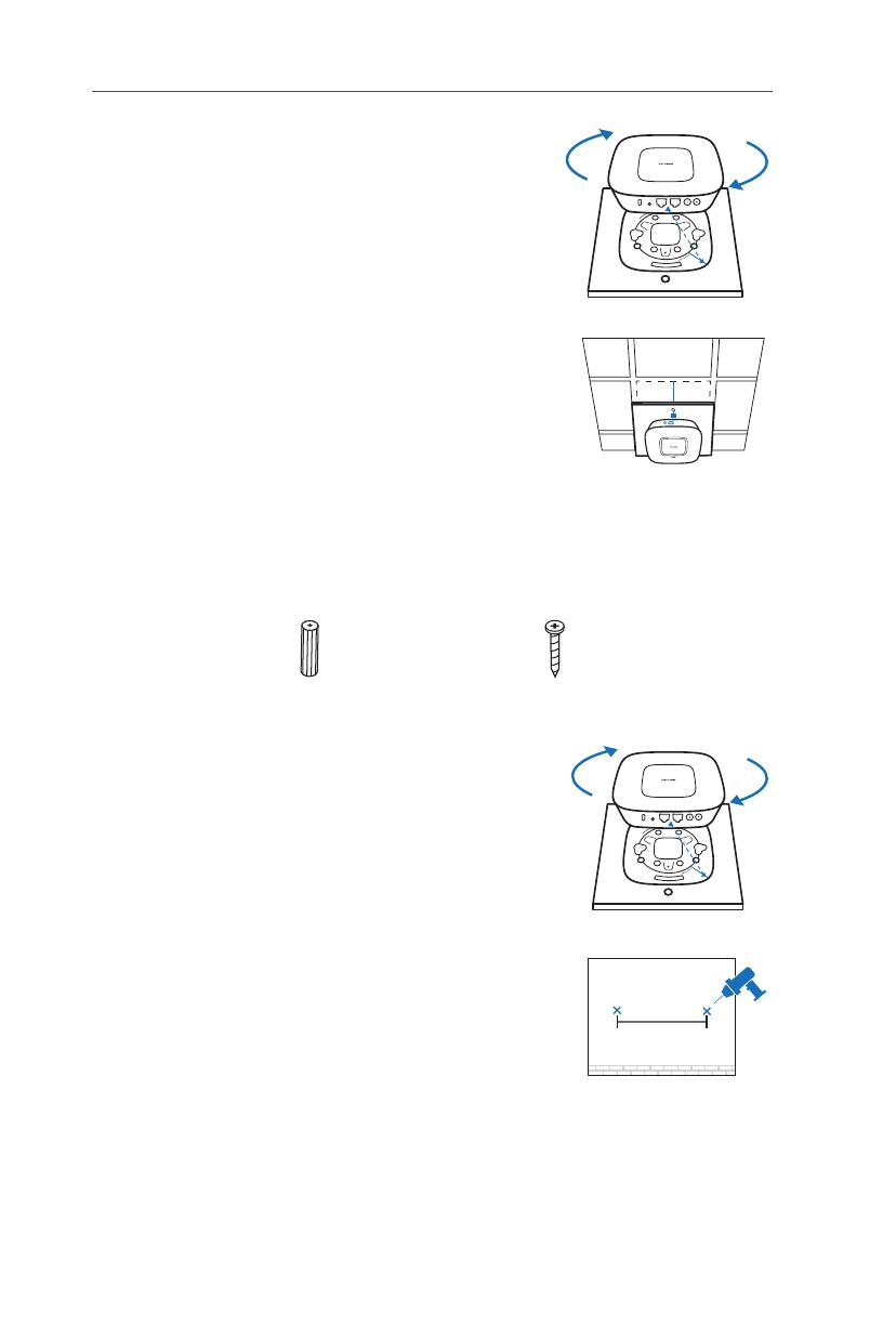
Fije el EAP al soporte de montaje alineando
la FLECHA 1 (en el EAP) con la FLECHA 2
(en el soporte de montaje), después rotar el
EAP en sentido de las manecillas del reloj
hasta que se fije en su lugar.
5
Coloque el cable Ethernet a través del orificio
y colocar la placa de techo de regreso en
su sitio. Conectar el cable de red al puerto
ETHERNET.
■
Opción 3: Montaje sobre la Pared
Siga los pasos que se muestran a continuación para instalar el EAP con los
accesorios suministrados:
1
Fije el EAP al soporte de montaje alineando la
FLECHA 1 (en el EAP) con la FLECHA 2 (en el
soporte de montaje), después rotar el EAP en
sentido de las manecillas del reloj hasta que se
fije en su lugar.
2
Realice dos marcas pequeñas con lápiz
sobre la pared. Asegúrese que las marcas
estén niveladas y deben tener 98.6mm de
separación. Taladrar dos perforaciones de
6mm a través del centro de sus marcas.
98.6mm
Taquetes de Pared de Plástico
M3×28 (Cantidad 4)
Tornillos auto-roscantes
M3×20 (Cantidad 4)


