
Soft-Starter
Arrancador Suave
Soft-Starter
SSW-05
User's Manual
Manual del Usuario
Manual do Usuário
Motors | Automation | Energy | Transmission & Distribution | Coatings


English-3
ENGLISH
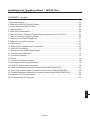
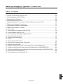
Installation and Operation Manual - SSW-05 Plus
1. Safety Instructions ........................................................................................................... 04
2. What is the SSW-05 Plus Soft-Starter.............................................................................. 04
3. How to identify the SSW-05 Plus ..................................................................................... 04
4. Technical Data................................................................................................................. 05
5. SSW-05 Plus Description................................................................................................ 06
6. Table of Powers / Currents / Power Wiring (copper wire at 70°C (158
o
F)) ........................ 06
7. Table of Connector Tightening Torque .............................................................................. 06
8. Capacity of the Power Supply Line .................................................................................. 07
9. Table of Fuses and Contactors ........................................................................................ 07
10. Dimensions ................................................................................................................... 07
11. SSW-05 Plus Installation and Connection ...................................................................... 08
12. SSW-05 Plus Setting .................................................................................................... 10
13. Operation of the Digital Relay Outputs ........................................................................... 11
14. Protections and Displays............................................................................................... 12
15. Overload Protection ...................................................................................................... 13
16. Reset ............................................................................................................................ 14
17. Faults and Possibles Causes ........................................................................................ 15
18. Solving the most frequent problems ............................................................................... 18
19.
SSW-05 Options and Accessories ................................................................................ 18
20. Table of Parameters (for serial communication/HMI-SSW05-RS)................................... 23
21. Error code and description (for serial communication / HMI-SSW05-RS) ....................... 24
22. Detailed Parameter Description (for serial communication/HMI-SSW05-RS)................. 24
23. Appendix for CE Conformance ...................................................................................... 30
24. EU Declaration of Conformity ........................................................................................ 32
Installation and Operation Manual - SSW-05 Plus
Version 2.3X - 0899.5119 /10
SUMMARY - English

English-4
ENGLISH
Installation and Operation Manual - SSW-05 Plus
SSW-05 - INSTALLATION AND OPERATION MANUAL
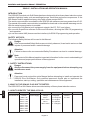
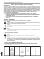
INTRODUCTION
The SSW-05 Plus electronic Soft-Starter has been designed to drive three-phase induction motors
applied to light duty loads, such as centrifugal pumps, small fans and screw compressors. If the
Soft-Starter shall be applied on heavy duty loads, please contact WEG.
The serial communication is available in the SSW-05 with software versions greater than V2.00.
The manual of the serial communication is available for download on the website www.weg.com.br.
With the serial communication is possible:
a)to connect the Soft-Starter in an equipment network, like PC, PLC, and others;
b)to use with SuperDrive software for Microsoft Windows, allowing the SSW-05 programming
and operation;
c)to use the remote HMI (human machine interface) for SSW-05 programming and operation.
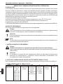
SAFETY NOTICES:
The following Safety Notices will be used in this Manual:
Danger
If the recommended Safety Notices are not strictly observed, it can lead to serious or fatal
injuries of personnel and/or material damage.
Attention
Failure to observe the recommended Safety Procedures can lead to material damage.
Note
The content of this Manual supplies important information for the correct understanding of
operation and proper performance of the equipment.
1. SAFETY INSTRUCTIONS:
Danger
Always disconnect the power supply from the equipment before attempting any
maintenance work.
Attention
Personnel must review this entire Manual before attempting to install and operate the
SSW-05 Plus Soft-Starter. Only qualified personnel should plan or implement the
installation, start-up, setting, operation and maintenance of this equipment.
2. WHAT IS THE SSW-05 PLUS SOFT-STARTER:
The SSW-05 Plus Soft-Starter allows smooth start/stop of three-phase induction motors.
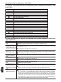
3. HOW TO IDENTIFY THE SSW-05 PLUS:
SSW05
Soft-Starter
WEG Series 05
0003
Rated Output
Current:
0003 = 3A
0010 = 10A
0016 = 16A
0023 = 23A
0030 = 30A
0045 = 45A
0060 = 60A
0085 = 85A
T
Three-phase
Power Supply
2246
Power Supply
Voltage:
2246 =
220 to 460V
4657 =
460 to 575V
E
Manual
Language:
P= Portuguese
E= English
S= Spanish
P
SSW-05
Version:
P= Plus
Z
End of Code
T - Trilingual

English-5
ENGLISH
Installation and Operation Manual - SSW-05 Plus
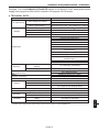
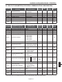
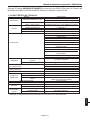
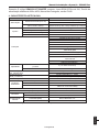
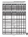
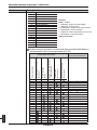
4. TECHNICAL DATA:
Example: The code SSW050010T2246PPZ means a 10A SSW-05 Plus, three-phase power
supply in the range from 220 to 460V, manual in Portuguese, PLUS version.
Model
AC Input Power
Control Voltage (A1 and A2)
Power supply
(R/1L1, S/3L2, T/5L3)
Settings
Pedestal Voltage
Acceleration Time
Deceleration Time
Motor Current
Diagnostics
Start Duty
Maximum Number of Starts
per hour
Starting Cycle
Digital Inputs
(90...250Vac 6mA)
Relay
Outputs (1A 250Vac)
Communication
Temperature
Ambient Humidity
Altitude
Degree of Protection
Polution Degree (UL508)
Mounting
Fastening
Enclosure
Electromagnetic Compatibility
(EMC)
Low Voltage
SSW-05 Plus
90 to 250Vac 50/60 Hz (+/- 6Hz)
200 mA
220 to 460 Vac (+10%,-15%) 50/60 Hz (+/- 5Hz) 3
460 to 575 Vac (+10%,-15%) 50/60 Hz (+/- 5Hz) 3
30 to 80% U
N
1 to 20 s
Off to 20 s
30 to 100% I
N
4 ( 1 start every 15 minutes)
3 x I
N
during 10 seconds
0 to 55°C (32to131°F)
5 to 90% Non Condensing
0 to 1000m (up to 13,200 ft (4000m) with
10% output current derating/1000m)
IP 00 (Chassis)
2
DIN 35mm rail or M4 fastening bolts
Molded plastic box
Class A (industrial use)
IEC 60947-4-2 Standard
UL 508 / IEC 60947-4-2
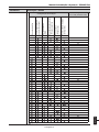
Standards
Motor Overload Protection
Incorrect Phase Sequence
Phase Loss
Immediate Overcurrent
Locked Rotor
Thyristor Overload
Immediate Overload at
By-pass Relay
Overcurrent before By-pass
Frequency out of Tolerance
Internal By-pass Relay
Contact is open
Undervoltage at control voltage
Immediate Undercurrent
(1)
DI1 – Enable/Disable Function
DI2 – Reset Function
Operation Function (13 – 14/23)
Full Voltage Function (14/23 – 24)
Serial Interface (RS232C)
(1)
Enable and Programmed only through serial communication or HMI-SSW05-RS.

English-6
ENGLISH
Installation and Operation Manual - SSW-05 Plus
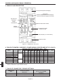
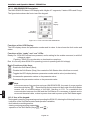
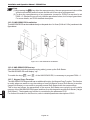
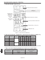
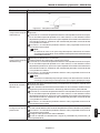
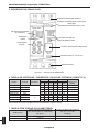
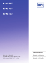
5. SSW-05 PLUS DESCRIPTION:
7. TABLE OF CONNECTOR TORQUE SETTINGS:
SSW-05 Plus
Size
1
2
Torque-Power Terminals
(R, S, T, U, V and W)
Nm (lb-in)
3.0 (32.7)
5.5 (60.0)
Nm (lb-in)
0.5 (4.5)
0.5 (4.5)
Torque of
Electronics Terminal
* According to able 45.2, UL508.
** Valid for Standard 4 pole WEG motors.
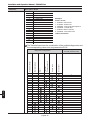
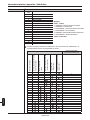
6. TABLE OF POWERS / CURRENTS / POWER WIRING (COPPER WIRE AT 70°C (158
O
F)):
Model
SSW-05.3
SSW-05.10
SSW-05.16
SSW-05.23
SSW-05.30
SSW-05.45
SSW-05.60
SSW-05.85
Rated
Current
3A
10A
16A
23A
30A
45A
60A
85A
220Vto240V*
HP kW
0.75 0.55
3 2.2
5 3.7
7.5 5.5
10 7.5
15 11
20 15
30 22
380Vto415V*
HP kW
1.5 1.1
5 3.7
7.5 5.5
10 7.5
15 11
25 18.5
30 22
50 37
440Vto480V*
HP kW
1.5 1.1
5 3.7
10 7.5
15 11
20 15
30 22
40 30
60 45
Power Wiring
mm
2
(AWG)
0.75 (18)
1.5 (16)
4 (12)
6 (10)
10 (8)
16 (6)
25 (4)
35 (2)
Size
1
2
525V**
kW
1.5
5.5
11
15
18.5
30
45
55
575V*
HP
2
7.5
10
20
25
40
50
75
Setting
Trimpots
Reset Button
Dip-switch for
Protection
Enable
Three-phase Input Power Supply
Reset (DI2)
Motor Enable/Disable Command (DI1)
Electronics Power Supply (A1 and A2)
SSW-05 Plus Status LEDS
Relay Output (13, 14/23 and 24)
Output to motor
Connector for Serial
Interface or HMI
Figure 5.1 - SSW05 Plus Front view

English-7
ENGLISH
Installation and Operation Manual - SSW-05 Plus
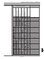
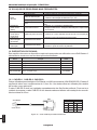
8. CAPACITY OF THE POWER SUPPLY LINE:
The SSW-05 Plus is suitable to be used in circuits that can not supply more than X A
RMS
(according
to table below) symmetric Ampères, Y Volts maximum:
SSW-05 Plus
Model
3A
10A
16A
23A
30A
45A
60A
85A
Y = 220- 575V
X (kA)
5
5
5
5
5
5
5
10
9. TABLE OF FUSES AND CONTACTORS (SEE ITEM 11):
SSW-05 Plus
Model
3A
10A
16A
23A
30A
45A
60A
85A
Contactor
(K1)
CWM09
CWM12
CWM18
CWM25
CWM32
CWM50
CWM65
CWM95
Fuse
(F1, F2,F3)
Type D 10A
Type D 16A
Type D 25A
Type D 35A
Type D 50A
Type D 63A
Type NH 100A
Type NH 125A
Fuse
(F11, F12, F21)
Type D 6A
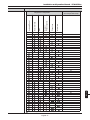
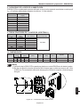
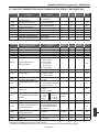
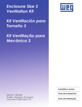
Size
1
2
Width
mm (in)
LLa
59 60.4
(2.32) (2.38)
79 80.4
(3.11) (3.17)
Depth P
mm (in)
145 (5.70)
172 (6.77)
Fixing A
mm (in)
51 (2.00)
71 (2.79)
Fixing B
mm (in)
122 (4.80)
177 (6.17)
Fixing
M4 screw/ Rail
M4 screw/ Rail
Weight
kg (Lb)
0.74 (1.63)
1.67 (3.68)
Height
mm (in)
HHa
130 130.7
(5.12) (5.15)
185 185.7
(7.28) (7.31)
Fixing D
mm (in)
61 (2.40)
99 (3.89)
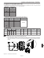
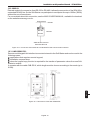
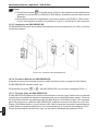
Notes
1) The SSW-05 Plus can be fixed on DIN 35mm rail.
2) If the fastening is made through a M4 bolt, bolt tightening torque should not be higher
than 1 Nm (8.85 Ib in). The use of a top fastening support is required as shown in figure
bellow:
10. DIMENSIONS:
Figure 10.1 - SSW-05 Plus Dimensions

English-8
ENGLISH
Installation and Operation Manual - SSW-05 Plus
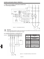
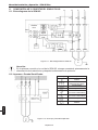
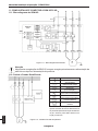
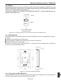
11.2. Simplified Start/Stop on 230V/400V line:
230/400V
Symbol
Description
Fuse
Disconnecting Switch
(opens under load)
Transformer
N.O. switch (with holding)
N.C. push button
(with automatic return)
N.O. push button
(with automatic return)
Contactor (coil)
SSW-05
Plus
Digital
Signal
Processor
DSP
DI
1
DI
2
Start
Serial
Commu-
nication
13
14/23
24
U/2T1
V/4T2
W/6T3
M
3~
CT
CT
HMI
P
3V3
P
5
P
12
N
12
A1 A2
R/1L1
S/3L2
T/5L3
F11
F1 F2 F3
NRST
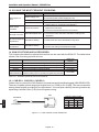
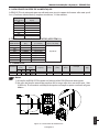
11. SSW-05 PLUS INSTALLATION AND CONNECTION:
11.1. Blockdiagram SSW-05:
Three-phase induction
motor
Attention
When applying the power supply for the first time in the SSW-05, first connect the control
power supply and then the main power supply.
Figure 11.1 - Blockdiagram SSW-05
Figure 11.2 - Simplified Start/Stop on 230V/400 line

English-9
ENGLISH
Installation and Operation Manual - SSW-05 Plus
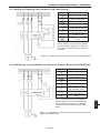
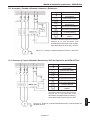
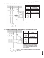
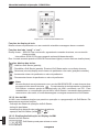
11.4. Start/Stop by using Push Button and Operation Function Relay of the SSW-05 Plus:
The “T1” transformer is only required when
the line voltage is out of the range allowed
for the electronics supply (90 – 250Vac).
For 400V, use neutral conductor (N) and one
phase.
11.3. Starting and Stopping using Contactor and Push Buttons:
The “T1” transformer is only required when
the line voltage is out of the range allowed
for the electronics supply (90 – 250Vac).
For 400V, use neutral conductor (N) and
one phase.
Symbol
Description
Fuse
Disconnecting Switch
(opens under load)
Transformer
N.O. switch (with holding)
N.C. push button
(with automatic return)
N.O. push button
(with automatic return)
Contactor (coil)
Three-phase induction
motor
Symbol
Description
Fuse
Disconnecting Switch
(opens under load)
Transformer
N.O. switch (with holding)
N.C. push button
(with automatic return)
N.O. push button
(with automatic return)
Contactor (coil)
Three-phase induction
motor
Figure 11.3 - Starting and Stopping using Contactor and Push Buttons
Figure 11.4 - Start/Stop by using Push Button and Operation Function
Relay of the SSW-05 Plus

English-10
ENGLISH
Installation and Operation Manual - SSW-05 Plus
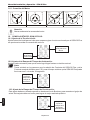
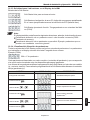
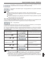
12.3. Setting of the deceleration ramp:
This setting should be used only for deceleration of pumps in order to reduce hydraulic shocks.
This setting must be made in order to obtain the best pump performance.
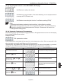
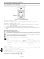
12. SSW-05 PLUS SETTING:
12.1. Pedestal Voltage Setting:
Set the pedestal voltage to a value that the motor starts to run as soon as run command is given by
the SSW-05 Plus.
12.2. Setting of the acceleration ramp time:
Set the value so that the motor accelerates to the rated speed.
Note:
Please consider that in the cases where rated SSW-05 Plus current is equal to the rated
motor current, the SSW-05 Plus can be operated, at maximum, during 10 seconds at 3 x
I
N.
Trimpot for the
pedestal voltage
setting
Trimpot for
the acceleration
Ramp time
setting
The dot
indicates the
factory default
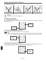
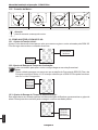
11.5. Motor Connection:
UV
W
N
U
V
W
UV W U
V
W
Attention
Only the motor frame shall be grounded.
CORRECT CORRECT
INCORRECT INCORRECT
Trimpot for the
deceleration
Ramp time
setting

English-11
ENGLISH
Installation and Operation Manual - SSW-05 Plus
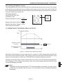
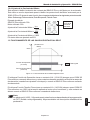
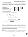
13. OPERATION OF THE DIGITAL RELAY OUTPUTS:
The relay of the Operation Function closes its N.O. contact (13-14/23) always when the SSW-05
Plus receives the enable command. This contact is open only at the end of the deceleration ramp
(when it is set via trimpot) or when the SSW-05 Plus receives the disable command.
The relay of the Full Voltage Function closes the N.O. contact (14/23-24) always when the SSW-
05 Plus applies 100% voltage to the driven motor. This contact opens when the SSW-05 Plus
receives the disable command.
Note
Depending on the programming of P277 (programmable relay output), the relay output
(14/23-24) may assume other functions. For more details refer to Detailed Parameter
Description.
t
t
t
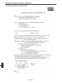
12.4. Setting of the Motor Current:
This setting defines the ratio of the SSW-05 Plus current and the driven motor current. The setting
of this value is very important, since it defines the protection of the motor driven by the SSW-05
Plus. The setting of this function has direct influence over the following motor protections: overcurrent,
overload, locked rotor, phase loss.
Calculation example:
Used SSW-05 Plus: 30A
Used Motor: 25A
Setting of the Motor Current =
I
Motor
I
SSW-05 Plus
Setting of the Motor Current
=
25A
30A
Setting of the Motor Current = 0.833
Thus it must be set at 83%.
Trimpot for
the motor
current
setting
100%
Operation Function
(13-14/23)
Full Voltage Function
(14/23-24)
U
N
(Motor Voltage)
Relay On
Figure 13 - Operation of the digital relay outputs.

English-12
ENGLISH
Installation and Operation Manual - SSW-05 Plus
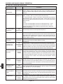
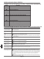
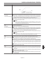
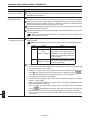
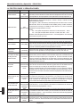
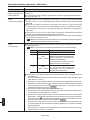
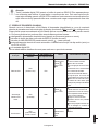
14. PROTECTIONS AND DISPLAYS:
Protection/Display Display
Description
LED
(overcurrent)
Overcurrent*
Phase Loss* LED
(Phase Loss)
Incorrect Phase LED
Sequence* (Phase Seq)
Locked Rotor* LED (Stall)
Motor overload LED
protection* (Overload)
Overcurrent of the LED
SSW-05 Plus (Internal Fault)
By-pass relay Flashes
5 times
LED
Overcurrent before Internal Fault)
By-pass Flashes
4 times
Thyristor LED
overload (Internal Fault)
Flashes
6 times
Frequency out LED
of Tolerance (Internal Fault)
Flash Once
Internal By-pass LED
relay contact is (Internal Fault)
open Flashes
3 times
LED
Undercurrent (Internal Fault)
Flashes
8 times
Activation
Monitoring is activated only when the SSW-05 Plus is in rated duty
(100% voltage). It trips, when the motor current exceeds 3 times the
value set with the trimpot (Motor Current) during a time longer than 1
second.
- At start: it acts when there is no voltage at the power supply terminals
(R/1L1, S/3L2 e T/5L3), or when motor is disconnected.
- In duty (full voltage – 100%). It acts after 1s after phase loss has been
detected both at the motor input and output. It acts when the current
that flows through the SSW-05 is lower than x% of current set at trimpot
Motor Current.
where:
x%= 20% for trimpot Motor Current or P105 between 50% - 100%
x%= 30% for trimpot Motor Current or P105 between 30% - 50%
It also acts when a current unbalance larger than 30% is detected
between the phases.
The error trips when in incorrect phase sequence
.
This protection trips during the transition between the end
of the acceleration ramp time and the contact closure of the internal by-
pass relays of the SSW-05 Plus, when the current flowing through the
SSW-05 Plus is higher than or equal to 2 times the current set with
trimpot (Motor Current).
This protection monitors constantly the motor current and compares it
with the value set by the trimpot (Motor Current).
See Item 15.
This protection monitors only when SSW-05 Plus is operating at full
voltage (100%). Is activated when the current is higher than the adjusted
value for more than 1 second. The activation level is 60A for the following
SSW-05 models: 3A to 30A. For the 45A to 85A models the activation
level is 200A. The internal fault LED flashes 5 times intermittently.
This protection trips during the transition between the end of the
acceleration ramp time and the contact making of the internal bypass
relays of the SSW-05 Plus, when the current flowing through the SSW-
05 Plus is higher or equal the rated level. The activation level is 37.5A for
the following SSW-05 models: 3A to 30A. For the 45A to 85A models
the activation level is 200A. The internal fault LED flashes 4
times
intermittently.
This protection monitors the current that flows through the SSW-05 Plus
during the acceleration and deceleration ramp time, and compares it
with the rated current of the SSW-05 Plus. Fig. 15.2 shows the trip time
curves when thyristors are overloaded. The internal fault LED flashes 6
times intermittently.
This protection trips when the line frequency is out of range (+/- 10%),
when compared with the rated frequency (50 Hz or 60Hz). The internal
fault LED flashes 1 time intermittently.
This protection monitors, if the contact of the internal by-pass relay of
the SSW-05 Plus is closed ( it operates only when the SSW-05 Plus is
operated at full voltage (100%). The internal fault LED flashes 3 times
intermittently.
Monitoring occurs only when the SSW-05 Plus reaches steady-state (100%
of voltage). It acts when the current that flows throught the SSW-05 is
lower than P610% of current set at trimpot motor current, for a time period
longer than the value set in P611.

English-13
ENGLISH
Installation and Operation Manual - SSW-05 Plus
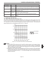
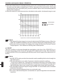
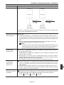
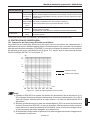
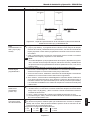
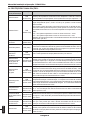
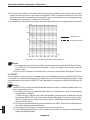
15. OVERLOAD PROTECTION:
15.1. Motor Electronic Overload Protection:
The motor overload electronic protection simulates the heating and cooling of the motor, also
known as thermal image.This heating simulation uses as input data the True RMS current. Fig.
15.1 shows the curve of the actuation time with motor under overload condition. The temperature
class of this function is, according to the IEC 947-4-2, Class 10.
t(s)
1 +
10
4
1 +
10
3
100
10
1
% Ief
Cold Condition
Hot Condition
* These protections may be enabled/disabled through the respective dip-switches.
Protection/Display
Display
Description
Activation
This protection monitors the control supply voltage of the electronics (A1
and A2) constantly and trip always when Vac voltage become lower than
80% of the rated voltage. The internal fault LED flashes 2 times intermittently.
It acts when the DI1Digital Input is open. The DI1 Digital Input must be
programmed to “External Fault” (P264=2). The internal fault LED flashes
intermittently 7 times.
- ON: SSW-05 Plus has been powered, and is waiting for the enable
command, or with full voltage at output.
- Flashing: SSW-05 Plus in acceleration/deceleration ramp time.
It is On only when SSW-05 Plus is operating (motor is operating with full
voltage).
Undervoltage in the LED
Control Supply (Internal Fault)
Flashes 2 times
External Fault LED
(Internal Fault)
Flashes 7 times
LED
Ready to operate (Ready)
In Operation LED
(Run)
Notes
1) When SSW-05 Plus electronics (A1 and A2) is without power control supply voltage,
the thermal image is saved internally. When the power supply voltage is re-established
again (A1 and A2), the value of the thermal image returns to the value present before
the loss of the power control supply.
2) Always the reset is performed via Digital Input 2 (DI2) or by means of the reset button
(SSW-05 front), the value of the thermal image returns to the value saved previously in
the internal Soft-Starter memory, i. e., the thermal image value of the last electronics
disable is returned;
100 200
300
400 500 600 700 800
Figure 15.1 - Curve of the motor electronic overload protection.

English-14
ENGLISH
Installation and Operation Manual - SSW-05 Plus
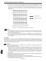
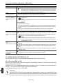
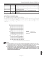
Notes
1)The thermal thyristor image is not saved in the internal Soft-Starter memory. When the
SSW-05 is enabled/reinitialized, the value of the thermal thyristor image assumes zero;
2)When the motor is running in full voltage, the cooling of the thyristor overload Thermal
Image happens. This is because of the By-pass of the thyristors.
16. RESET:
The error condition can be reset through the reset button at the front of the SSW-05 Plus, or
through a momentary contact closure (0.5 seconds) at DI2 (digital input for reset). Other alternative
to reset the SSW-05 Plus is by switching On/Off the power control supply of the electronics (A1
and A2).
Notes
The SSW-05 Plus also provides the automatic reset by enabling this function through the
dip-switch (auto):
1)The automatic reset occurs after 15 minutes in the following fault conditions:
- Overcurrent, Phase Loss, Locked Rotor, Immediate overcurrent of the SSW-05 Plus
by-pass relay, Overcurrent before By-pass, Frequency out of tolerance, Contact of the
internal By-pass relay is open, power control supply undervoltage and External Fault.
2)The automatic reset time may be changed at P206. For more details refer to Detailed
Parameter Description.
3)For incorrect phase sequence there is no automatic reset.
4)For motor overload and thyristor overload there is a specific algorithm for the automatic
reset time.
Figure 15.2 - Curve of the thyristor overload.
t(s)
1 +
10
3
100
10
1
0.1
100 200 300 400 500 600 700 800
% In
Cold Condition
Hot Condition
3) The reset of the electronic overload protection can be set to manual function (man). In this case
the reset must be made via digital input 2 (DI2) or by means of the reset button. If the reset
setting has been set to automatic (auto), the error condition will be reset automatically after the
cooling of the equipment;
4) When the electronic overload protection is disabled via dip-switch, the thermal image is reset.

English-15
ENGLISH
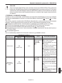
Installation and Operation Manual - SSW-05 Plus
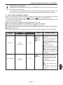
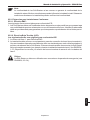
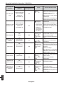
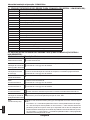
Protection
Description
Phase Loss
Motor Overload
SSW-05
Front Panel
LED
(Phase Loss)
LED
(Overload)
HMI-SSW05-RS
(see chapter 19.3)
E03
E05
Possibles
Causes
Phase fault in the three-phase
network
Short-circuit or thyristor fault
Motor is not connected
Motor connection is not correct
Driving problems with the input
contactor.
Input fuses are blown.
Incorrect programming of the
Motor Current Trimpot or P105.
Motor current consumption
lower than required for
actuation of the phase loss
protection.
“Motor Current” trimpot or
P105 (motor current) has
been set incorrectly. The set
value is too low for the motor
being used.
Load on the motor shaft too
high.
Too much successive motor
starts.
The value of the thermal
protection saved when
switching
Fault Display
Reset
Power-on
Reset
key
key
Auto-reset
DI2.
Power-on
key
Auto-reset
Attention - Very Important
Both digital input (DI2) and reset button of the SSW-05 Plus should be used only for the
reset after a fault condition.
If the reset function is used when the SSW-05 Plus is operating at rated voltage, the
internal by-pass relays will open their contacts under load, thus jeopardizing their life.
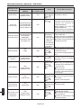
17. FAULTS AND POSSIBLE CAUSES:
When a fault is detected, the Soft-Starter is disabled and the Fault Code is displayed by flashing
LED´s or on the readout display in the EXX form, where XX is the actual Fault Code.
To restart the Soft-Starter after a fault has occurred, the Soft-Starter must be reset. In general, the
reset can be made as follows:
disconnecting and reapplying the AC power (power-on reset);
by pressing the key “RESET” on the SSW05-RS front panel (reset key);
through the HMI-SSW05-RS by pressing the key (manual reset);
automatic reset by enabling the function through the dip-switch (auto) or though P106 and P220.
via digital input: DI2.
Table below explains how to reset the fault and show the possible causes for each Fault Code.

English-16
ENGLISH
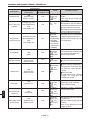
Installation and Operation Manual - SSW-05 Plus
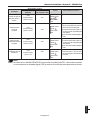
Protection
Description
External Fault
Error in the Copy
Function
Keypad HMI
Connection Fault
Locked Rotor
Thyristor overload
Undercurrent
Overcurrent
Incorrect phase
sequence
Undervoltage in the
Control Supply
SSW-05
Front Panel
LED
(Internal Fault)
flashes 7 times
Available only when
HMI-SSW05-RS is
used
(see chapter 19)
Available only when
HMI-SSW05-RS is
used
(see chapter 19)
LED
(Stall)
LED
(Internal Fault)
flashes 6 times
LED
(Internal Fault)
flashes 8 times
LED
(Overcurrent)
LED
(Phase Seq)
LED
(Internal Fault)
flashes 2 times
HMI-SSW05-RS
(see chapter 19.3)
E06
E10
E31
E63
E64
E65
E66
E67
E70
Possibles Causes
off return when switching on
again.
The wiring at DI1 is open (not
connected).
Attempt for copying HMI
Parameters to the Soft-Starters
with different software versions.
Keypad cable misconnected.
Electrical noise in the installation
(electromagnetic interference).
Keypad cable misconnected.
Electrical noise in the installation
(electromagnetic interference).
Reset is executed through DI2
or reset button.
The time programmed for the
acceleration ramp is shorter than
the actual acceleration time.
Motor shaft is locked.
Load on the motor shaft too high.
Too much successive starts.
Current value programmed in
P610 may be much higher than
the minimum motor operation
current.
Motor at no load.
In applications with hydraulic
pumps, the pump may be
operating at no load.
Short-circuit between phases.
Momentary motor overload.
Motor shaft is locked.
Network phase sequence
inverted at the input.
Electronics supply lower than the
required one.
Electronic power supply with bad
contact.
Fuse of the electronics power
supply is blown.
Fault Display
Reset
Power-on
Reset key
key
DI2.
Power-on
key
Power-on
This fault
disappears
automa-tically
when HMI
reestablishes
the communi-
cation with the
Soft-Starter.
Power-on
Reset key
key
Auto-reset
DI2.
key
Auto-reset
Power-on
Reset button
key
Auto-reset
DI2.
Power-on
Reset key
key
DI2.
Power-on
Reset key
key
Auto-reset
DI2.
Power-on
Reset key
key
Auto-reset
DI2.

English-17
ENGLISH
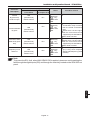
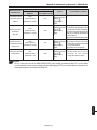
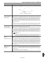
Installation and Operation Manual - SSW-05 Plus
Possibles Causes
SSW-05 is defective.
The time programmed for the
acceleration ramp is shorter
than the actual acceleration
time.
Rated motor current higher
than the current that can be
supported by the Soft-Starter.
Motor shaft is locked
Short-circuit between phases.
Rated motor current higher
than the current that can be
supported by the Soft-Starter.
Motor shaft is locked.
The line frequency is out of ran-
ge (+/- 10%), when compared
with the rated frequency (50Hz
or 60Hz).
Protection
Description
Internal
By-pass relay
contact is open
Overcurrent before
By-pass
Overcurrent of the
SSW-05 By-pass
relay
Frequency out of
tolerance
SSW-05
Front Panel
LED
(Internal Fault)
flashes 3 times
LED
(Internal Fault)
flashes 4 times
LED
(Internal Fault)
flashes 5 times
LED
(Internal Fault)
flashes 1 time
HMI-SSW05-RS
(see chapter 19.3)
E71
E72
E73
E75
Fault Display
Reset
Power-on
Reset
key
key
Auto-reset
DI2.
Power-on
Reset key
key
Auto-reset
DI2.
Power-on
Reset key
key
Auto-reset
DI2.
Power-on
Reset key
key
Auto-reset
DI2.
Note
To prevent the E31 fault, when HMI-SSW05-RS is applied, please no avoid resetting the
fault through the digital inputs (DI2) and through the reset key located on the SSW-05 front
panel.

English-18
ENGLISH
Installation and Operation Manual - SSW-05 Plus
18. SOLVING THE MOST FREQUENT PROBLEMS:
Problem
Motor does not
runs
Motor speed
oscillates
Motor speed
too high or too low
Shocks during pump
deceleration
Shocks during pump
acceleration
Points to be checked
Wrong wiring
Power Supply Loss
Setting
Fault
Loose connections
Motor Nameplate Data
Soft-Starter Setting
Soft-Starter Setting
Corrective Actions
1. Check all power and control connections
1. Check the power supply (R, S, T)
2. Check the power control supply (A1, A2)
1. Check if the settings are correct for the application.
1. Check if the SSW-05 Plus is not in locking condition
(refer to item 14 – Protections and Display).
1. Switch Off the SSW-05 Plus, switch off the power supply and
tighten all connections.
2. Check all internal SSW-05 Plus connections.
1. Check if the motor has been selected according to the
application.
1. Reduce the time of the deceleration ramp time.
1. Reduce the time of the acceleration ramp time.
2. Reduce the setting of the pedestal voltage.
19. SSW-05 OPTIONS AND ACCESSORIES:
This chapter describes the optional devices that can be used with the SSW-05. The table below
shows a list of existing optional devices.
Name
CAB-RS-1
CAB-RS-2
CAB-RS-3
MIW-02
HMI-SSW05-RS
Function
Cable for the remote serial keypad - cable: 1m (3.28ft)
Cable for the remote serial keypad - cable: 2m (6.56ft)
Cable for the remote serial keypad - cable: 3m (9.84ft)
RS-232 to RS-485 conversion module
External serial Keypad HMI. For remote use with the
CAB-RS cable (up to 3m (9.84ft)). Keypad Copy Function.
WEG Item
Number
0307.7827
0307.7828
0307.7829
417100543
417100996
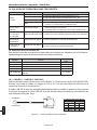
19.1. CAB-RS-1, CAB-RS-2, CAB-RS-3:
Cables used to connect the Soft-Starter to the external serial interface keypad (HMI-SSW05-RS).
There are 3 cables options ranging in lenghts from 1m (3.28ft) to 3m (9.84ft). The user must select
among these lengths according to his requirement. You must plan carefully the wiring location by
separating it at least 10cm (3.9in) from the power wiring.
Table 19.1 - Available optional devices for the SSW-05.
Soft-Starter
RJ Connector
HMI
DB9 Connector
DB9 PINS
1 Vdc
2RX
3TX
5 GND
CABLE CONECTIONS
RJ PINS
1 Vdc
6TX
4RX
5 GND
Figure 19.1 - Cable CAB-RS for HMI-SSW05-RS.

English-19
ENGLISH
Installation and Operation Manual - SSW-05 Plus
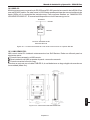
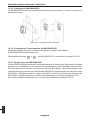
19.2. MIW-02:
External module for conversion from RS-232 to RS-485: it allows the connection of the SSW-05 to
a standard RS-485 line. So the Soft-Starter can participate in a multipoint line up to 1000m (3280ft)
without the use of transducers.
For more details about this connection, see the MIW-02 USER MANUAL, available for download
on the website www.weg.com.br .
Figure 19.2 - Connection of the SSW-05 to a standard RS-485 communication network.
Weg Network
RS-485
MIW-02
SSW-05 RJ Connector
Serial Port RS-232
RS-485
RS-232
19.3. HMI-SSW05-RS:
Remote serial keypad: this interface is mounted external to the Soft-Starter and can be used in the
following cases:
applications that require a remote keypad;
installation on panel door;
when the keypad copy function is required for the transfer of parameter values from one Soft-
Starter to another.
It operates with the cable CAB-RS-X, which length must be chosen according to the needs (up to
9.84ft).
Figure 19.3 - Dimensions of the HMI-SSW05-RS.

English-20
ENGLISH
Installation and Operation Manual - SSW-05 Plus
Figure 19.4 - Front view of the HMI-SSW05-RS.
Functions of the LED Display:
The LED display shows the parameter number and its value. It also shows the fault codes and
status.
Functions of the “ready” and “run” LEDs:
Ready: On - SSW-05 Plus has been powered, and is waiting for the enable command, or with full
voltage at output.
Flashing - SSW-05 in acceleration or deceleration ramp time.
Run: It is On only when SSW-05 is operating (motor is operating with full voltage).
Led “Run”
Led “Ready”
LED
Display
Basic Functions of the Keys:
- Enable the Soft-Starter (Start);
- Disable the Soft-Starter (Stop). Also resets the Soft-Starter after a fault has occurred;
- Toggles the LED display between parameter number and its value (number/value);
- Increases the parameter number or the parameter value.
- Decreases the parameter number or the parameter value.
Note
In the occurrence of errors when using an HMI-SSW05-RS, the reset of errors must be
done through the key . Reset through the key present in the frontal of the Soft-Starter
causes loss of communication of the HMI, resulting in E31. To re-establish the
communication between the HMI and the Soft-Starter it is necessary to detach and to
reconnect the serial cable, or else to power down and to power up the Soft-Starter again.
19.3.2. Use of the keypad:
The keypad is used for programming and operating the SSW-05, allowing the following functions:
- indication of the Soft-Starter status and operation variables;
- fault indication and diagnostics;
- viewing and programming parameters;
- operation of the Soft-Starter (Keys and ).
19.3.1. HMI-SSW05-RS Description:
The HMI-SSW05-RS has a LED display with 4 digits of 7 segments, 2 status LEDs and 5 keys.
The figure below shows the front view of the keypad.
A página está carregando...
A página está carregando...
A página está carregando...
A página está carregando...
A página está carregando...
A página está carregando...
A página está carregando...
A página está carregando...
A página está carregando...
A página está carregando...
A página está carregando...
A página está carregando...
A página está carregando...
A página está carregando...
A página está carregando...
A página está carregando...
A página está carregando...
A página está carregando...
A página está carregando...
A página está carregando...
A página está carregando...
A página está carregando...
A página está carregando...
A página está carregando...
A página está carregando...
A página está carregando...
A página está carregando...
A página está carregando...
A página está carregando...
A página está carregando...
A página está carregando...
A página está carregando...
A página está carregando...
A página está carregando...
A página está carregando...
A página está carregando...
A página está carregando...
A página está carregando...
A página está carregando...
A página está carregando...
A página está carregando...
A página está carregando...
A página está carregando...
A página está carregando...
A página está carregando...
A página está carregando...
A página está carregando...
A página está carregando...
A página está carregando...
A página está carregando...
A página está carregando...
A página está carregando...
A página está carregando...
A página está carregando...
A página está carregando...
A página está carregando...
A página está carregando...
A página está carregando...
A página está carregando...
A página está carregando...
A página está carregando...
A página está carregando...
A página está carregando...
A página está carregando...
A página está carregando...
A página está carregando...
A página está carregando...
A página está carregando...
A página está carregando...
A página está carregando...
A página está carregando...
A página está carregando...
-
 1
1
-
 2
2
-
 3
3
-
 4
4
-
 5
5
-
 6
6
-
 7
7
-
 8
8
-
 9
9
-
 10
10
-
 11
11
-
 12
12
-
 13
13
-
 14
14
-
 15
15
-
 16
16
-
 17
17
-
 18
18
-
 19
19
-
 20
20
-
 21
21
-
 22
22
-
 23
23
-
 24
24
-
 25
25
-
 26
26
-
 27
27
-
 28
28
-
 29
29
-
 30
30
-
 31
31
-
 32
32
-
 33
33
-
 34
34
-
 35
35
-
 36
36
-
 37
37
-
 38
38
-
 39
39
-
 40
40
-
 41
41
-
 42
42
-
 43
43
-
 44
44
-
 45
45
-
 46
46
-
 47
47
-
 48
48
-
 49
49
-
 50
50
-
 51
51
-
 52
52
-
 53
53
-
 54
54
-
 55
55
-
 56
56
-
 57
57
-
 58
58
-
 59
59
-
 60
60
-
 61
61
-
 62
62
-
 63
63
-
 64
64
-
 65
65
-
 66
66
-
 67
67
-
 68
68
-
 69
69
-
 70
70
-
 71
71
-
 72
72
-
 73
73
-
 74
74
-
 75
75
-
 76
76
-
 77
77
-
 78
78
-
 79
79
-
 80
80
-
 81
81
-
 82
82
-
 83
83
-
 84
84
-
 85
85
-
 86
86
-
 87
87
-
 88
88
-
 89
89
-
 90
90
-
 91
91
-
 92
92


Automation Direct SSW-05 Soft Manual do usuário
- Tipo
- Manual do usuário
em outras línguas
Artigos relacionados
-
Automation Direct SSW08 Guia de instalação
-
Automation Direct SSW-07 Guia de instalação
-
 Automation Direct SSW-07 Soft Manual do usuário
-
 Automation Direct SSW07-08-KRS-485 RS-485 Kit Guia de instalação
-
 Automation Direct SSW0708900-KVT-3C Enclosure Size 3 Ventilation Kit Guia de instalação
-


