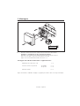
Marantec Command 801 Manual do proprietário
- Tipo
- Manual do proprietário

Command 801
Bedienungsanleitung
Transponder
Operating Instructions
Transponder
Notice d’utilisation
Transpondeur
Handleiding
Transponder
Instrucciones de manejo
Transponder
Istruzioni d’uso
Radar secondario (transponder)
Instruções de serviço
Transponder
D
GB
F
NL
E
I
P
Bitte sorgfältig aufbewahren.
Keep these instructions for later reference.
A conserver soigneusement.
Deze handleiding zorgvuldig bewaren.
A conservar cuidadosamente.
Da conservare con cura.
Guardar cuidadosamente.

2

3
Command 801
Seite 4 - 11
Page 12 - 19
Page 20 - 27
Blz. 28 - 35
Página 36 - 43
Pagina 44 - 51
Página 52 - 59
Deutsch
English
Française
Nederlands
Español
Italiano
Português

Deutsch / Seite 4
1. Inhaltsverzeichnis
Kapitel Seite
1. Inhaltsverzeichnis 4
2. Allgemeines 5
3. Montage 6
4. Programmieranleitung 8
4.1 Programmierung Transponder 8
4.2 Löschen 10
5. Technische Daten 11

Deutsch / Seite 5
In dem System Transponder Marantec können bis zu 14 Transponder gespeichert werden.
Mit den gespeicherten Transpondern wird im normalen Betriebsmodus ein Relais aktiviert,
solange sich eine gültige Karte im Lesebereich befindet.
Alle Programmierungen von Transpondern sind ohne Zugang zur Transponder-Elektronik möglich.
Hinweis:
Sämtliche Programmierungsänderungen können nur über die mitgelieferte Masterkarte
erfolgen. Kennzeichnen Sie die Masterkarte durch Aufkleben der beiliegenden Kurz-
anleitung in Ihrer Landessprache.
2. Allgemeines

Deutsch / Seite 6
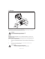
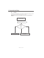
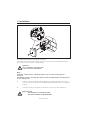
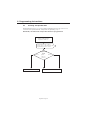
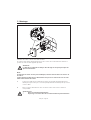
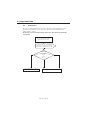
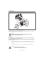
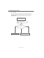
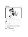
Die Montage der Leseantenne erfolgt an der Außenwand.
Die Transponder-Elektronik wird gegenüberliegend an die Innenseite montiert, so dass beide
Geräte mit der Anschlussleitung verbunden werden können.
Achtung:
Die Anschlussleitung darf nicht verlängert werden,
da dieses zu Betriebsstörungen führen kann!
Hinweis:
Bei Montage auf einer Metallfläche muss ein Abstand zum Gehäuse von mind. 2 cm
eingehalten werden.
Die Bohrung für die Anschlussleitung muß mittig zwischen den 4 Befestigungslöchern
für die Leseantenne angeordnet sein.
1. Führen Sie die Verbindungsleitung durch Bohrung zur Transponder-Elektronik und
schrauben Sie die Gehäuseunterschale an, so dass die Leitung vom Gehäuse abgedeckt
wird.
2. Befestigen Sie den Gehäusedeckel mit der Schraube und verschließen Sie die
Schrauböffnung mit der Abdeckkappe.
Achten Sie auf:
• die richtige Positionierung des Gehäuses
• eine glatte Verlegung der Leitung an der Unterseite
3. Montage

Deutsch / Seite 7
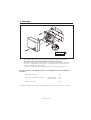
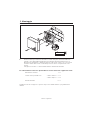
3. Befestigen Sie das Gehäuse für die Transponder-Elektronik an der Innenseite der
Anlage (Beachten Sie die Leitungslänge der Leseantenne!).
Führen Sie die Anschlussleitungen seitlich oder von der Unterseite in das Gehäuse ein.
Entsprechende Öffnungen im Gehäuse sind hierfür vorgesehen und müssen ausgebrochen
werden.
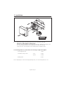
Schließen Sie die zwei Anschlussdrähte der Leseantenne an die Klemme 6 und 7 an.
Für Anschluss ohne Systemkabel gilt folgende Belegung:
Spannungsversorgung 24 V DC 1 und 2
Potentialfreier Relaiskontakt Schließer: 5 und 3
Öffner: 5 und 4
Leseantenne 6 und 7
Verschließen Sie nach Beendigung der Anschluss- und Programmierarbeiten das Gehäuse mit dem
Deckel.
1 2 3 4 5 6 7 8
123
4
5
6
7
8
3. Montage

Deutsch / Seite 8
4. Programmieranleitung
4.1 Programmierung Transponder
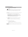
Achtung:
Während der Programmierung erfolgen zu Testzwecken mehrfache
Schaltfunktionen des Relais.
Stellen Sie vor dem Beginn der Programmierung sicher, dass durch diese
Schaltvorgänge in Zusammenhang mit einer nachgeschalteten Anlage
keine Gefahrensituation entsteht!
Der Programmiermodus wird durch Annäherung der Masterkarte in den Lesebereich der
Antenne aktiviert.
1. Halten Sie die Masterkarte für die Zeit von mindestens 14 Sekunden an die
Leseantenne.
Innerhalb dieser Zeit werden alle bisher gespeicherten Transponder gelöscht,
anschließend wechselt das Gerät für 15 Sekunden in den Programmiermodus.
Entfernen Sie innerhalb dieser Zeit die Masterkarte aus dem Lesebereich,
da das Gerät sonst den Programmiermodus wieder verlässt!
2. Halten Sie neu zu speichernde Transponder einzeln nacheinander an die
Leseantenne.
Mehrfach eingelesene Transponder werden nur einmal gespeichert.
Nach jedem Lesevorgang wird die Zeit für den Programmiermodus wieder neu
gestartet.
3. Der Programmiervorgang wird abgeschlossen durch:
• Anlegen der Masterkarte
• Speicherung von 14 verschiedenen Transpondern
• Automatisch, wenn 15 Sekunden lang kein weiterer Transponder eingelesen
wurde
Hinweis:
Nach Abschluss der Programmierung können nachträglich keine weiteren Transponder
gespeichert werden.

Deutsch / Seite 9
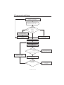
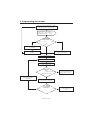
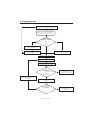
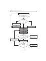
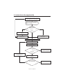
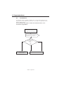
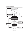
4. Programmieranleitung
Mastertransponder an Leseantenne halten
Zeitdauer 14-29 Sekunden
Programmier-
modus 'Löschen'
<14 Sek. Zeitdauer <29 Sek.
>14 Sek. -
<29 Sek.
Relais zieht 16 mal kurzzeitig an
in einer Zeit von 14 Sek., anschließend
Programmiermodus für 15 Sek.
Programmierung bleibt
unverändert erhalten
Neue Programmierung nicht
möglich
Alle Codierungen
sind gelöscht
Alle Codierungen sind gelöscht
Programmiermodus aktiv
Transponder kurzzeitig an
Leseantenne halten
Transpondertyp
Mastertransponder
Standardtransponder
Ende der Programmierung;
bisher programmierte
Transponder sind gespeichert
Programmierung von Transponder
'n' abgeschlossen
Neue Programmierung durch
Anlegen eines weiteren
Transponders möglich
'n' = Anzahl
der programmierten
Transponder
n<14 n=14
Ende der Programmierung;
14 Transponder sind
gespeichert

Deutsch / Seite 10
Mastertransponder an
Leseantenne halten
Zeitdauer 14-29 Sekunden
Relais zieht 16 mal kurzzeitig an
in einer Zeit von 14 Sek., anschließend
Programmiermodus für 15 Sek.
Programmierung bleibt
unverändert erhalten
Alle Codierungen
sind gelöscht
4. Programmieranleitung
Programmier-
modus
<14 Sek. Zeitdauer <29 Sek.
>14 Sek. -
<29 Sek.
4.2 Löschen
Das Löschen von Transpondern ( z. B. als Schutz vor unbefugter Benutzung bei Verlust )
geschieht wie bei 'Programmierung Transponder', Schritt 1.
Anschließend müssen alle 'berechtigten' Transponder neu programmiert
werden!

Deutsch / Seite 11
5. Technische Daten
Versorgungsspannung:
24 V DC +/- 25%
Stromaufnahme:
35 mA standby
55 mA aktiv
Ausgang:
Relaiskontakt, potentialfrei
Wechsler
30 V; 3 A
Anschluss:
Anschlußkabel 2 m mit Systemstecker
zum Anschluß an Steuerung
Temperaturbereich:
-15°C bis +65°C Transponder und Auswerteelektronik
-20°C bis +65°C Leseantenne
Lesereichweite:
70 mm mit Transponderkarte
50 mm mit Schlüsselanhänger
Leitungslänge von Leseantenne:
max. 1m
Betriebsfrequenz:
125 KHz
Kapazität:
14 Transponder + 1 Master-Transponder
Abmessungen Leseantenne:
104 x 94 x 25 mm (HxBxT)
Abmessungen Auswerteelektronik:
104 x 94 x 30 mm (HxBxT)
Schutzart:
Leseantenne: IP 65
Auswerteelektronik: Nur für trockene Räume

English / Page 12
1. Contents
CHAPTER page
1. Contents 12
2. General Information 13
3. Installation 14
4. Programming Instructions 16
4.1 Transponder Programming 16
4.2 Deleting Transponder Data 18
5. Technical Details 19

English / Page 13
The Marantec Transponder System can store up to 14 transponders. With the stored transpon-
ders, in the normal operating mode a relay is activated as long as a valid card is located within the
reading range. The entire transponder programming can be carried out without the need to access
the transponder electronics.
Note:
Any programming changes can only be effected via the supplied master card. Designate
the master card by applying the supplied sticker containing brief instructions in your
national language.
2. General Information

English / Page 14
The reading aerial is fitted to the outside of the wall.
The transponder electronics are installed opposite on the inside of the wall which allows both
devices to be connected via the connecting cable.
Attention:
Do not extend the connecting cable,
as this could cause malfunctions!
Note:
If fitting to a metal surface, a minimum distance of 2 cm to the housing must be
observed.
The drill hole for the connecting cable must be sited centrally between the 4 fixing holes
for the reading aerial.
1. Feed the connecting cable through the drill hole to the transponder electronics and
screw on the bottom casing of the housing, making sure that the cable is covered by the
housing.
2. Secure the housing cover with the screw and close off the screw hole with the cap.
Make sure that:
• the housing is correctly positioned
• the cable is laid flat on the underside
3. Installation

English / Page 15
3. Fasten the housing for the transponder electronics to the inside of the wall
(observe the cable length for reading aerial).
Feed the connecting cables into the housing from the side or underside. Provided for this
are corresponding openings in the housing which must be broken through.
Connect the two connecting wires of the reading aerial to terminals 6 and 7.
If connecting without a system cable, the following configuration applies:
Power supply 24 V DC 1 and 2
Potential-free relay contact closer: 5 and 3
opener: 5 and 4
Reading aerial 6 and 7
After completing the connection and programming work, close the housing with the cover.
1 2 3 4 5 6 7 8
123
4
5
6
7
8
3. Installation

English / Page 16
4. Programming Instructions
4.1 Programming the Transponders
Attention:
During programming, the relay goes through several switching functions for
test purposes.
Before commencing with programming, make sure that no hazardous
situations can occur as a result of these switching processes affecting a linked
system downline.
The programming mode is activated by holding the master card within the reading range
of the aerial.
1. Direct master card for min. 14 sec to the reading aerial.
During this time all transponders saved already are deleted, then the unit changes
to programming mode for 15 sec.
Remove the mastercard from the reading range within this time, otherwise
the system will quit the programming mode.
2. Hold transponders to be stored against the reading aerial one after the other.
Transponders which have been read into the system more than once are only stored
once.
After every reading procedure the time for programming mode is started again.
3. The programming procedure is completed on:
• introducing the master card
• storing 14 different transponders
• automatically, if during 15 sec. no further transponder is read
Note:
After programming has been completed, no further transponders can be subsequently
stored.

English / Page 17
4. Programming Instructions
Hold master transponder against reading
aerial for a period of 14-29 seconds
Programming
mode 'delete'
<14 secs. period <29 secs.
>14 secs. -
<29 secs.
Relay briefly picks up 16 times
for first 14 secs., then changes to
programming mode for 15 secs.
Programming remains
unchanged
Reprogramming not
possible
All codes are deleted
All codes are deleted
Programming mode active
Briefly hold transponder
against reading aerial
Transponder
type
Master transponder
Standard transponder
End of programming:
previously programmed
transponders are stored.
Programming of 'n'
transponder(s) completed
Reprogramming possible by
introducing a further
transponder
'n' = number
of programmed
transponders
n<14 n=14
End of programming:
14 transponders are
stored

English / Page 18
Hold master transponder
against reading aerial for
a period of 14-29 secs.
Relay briefly picks up 16 times
for first 14 secs., then changes to the
programming mode for 15 secs.
Programming remains unchanged
All codes are deleted.
4. Programming Instructions
Programming
mode
<14 secs. period <29 secs.
>14 secs. -
<29 secs.
4.2 Deleting Transponder Data
Deleting transponders (e.g. to protect against unauthorised use in the event of loss)
is carried out as explained under 'Transponder Programming', step 1.
Afterwards, all 'authorised' transponders must be reprogrammed!

English / Page 19
5. Technical Details
Supply voltage:
24 V DC +/- 25 %
Current input:
35 mA standby
55 mA active
Output:
Relay contact, potential-free
Change-over contact
30 V, 3 A
Connection:
2 m long connecting cable with system plug
for connection to control unit
Temperature tolerance:
- 15˚C up to + 65˚C transponder with decoder electronics
- 20˚C up to + 65˚C reading aerial
Reading range:
70 mm with transponder card
50 mm with key ring
Length of cable from reading aerial:
max. 1 m
Operating frequency:
125 KHz
Capacity:
14 transponders + 1 master transponder
Dimensions of reading aerial:
104 x 94 x 25 mm (HxWxD)
Dimensions of decoder electronics:
104 x 94 x 30 mm (HxWxD)
Protection category:
Reading aerial: IP 65
Decoder electronics: for dry premises only

Français / Page 20
1. Sommaire
Chapitre Page
1. Sommaire 20
2. Généralités 21
3. Montage 22
4. Programmation 24
4.1 Programmation du transpondeur 24
4.2 Effacement 26
5. Caractéristiques techniques 27
A página está carregando...
A página está carregando...
A página está carregando...
A página está carregando...
A página está carregando...
A página está carregando...
A página está carregando...
A página está carregando...
A página está carregando...
A página está carregando...
A página está carregando...
A página está carregando...
A página está carregando...
A página está carregando...
A página está carregando...
A página está carregando...
A página está carregando...
A página está carregando...
A página está carregando...
A página está carregando...
A página está carregando...
A página está carregando...
A página está carregando...
A página está carregando...
A página está carregando...
A página está carregando...
A página está carregando...
A página está carregando...
A página está carregando...
A página está carregando...
A página está carregando...
A página está carregando...
A página está carregando...
A página está carregando...
A página está carregando...
A página está carregando...
A página está carregando...
A página está carregando...
A página está carregando...
A página está carregando...
-
 1
1
-
 2
2
-
 3
3
-
 4
4
-
 5
5
-
 6
6
-
 7
7
-
 8
8
-
 9
9
-
 10
10
-
 11
11
-
 12
12
-
 13
13
-
 14
14
-
 15
15
-
 16
16
-
 17
17
-
 18
18
-
 19
19
-
 20
20
-
 21
21
-
 22
22
-
 23
23
-
 24
24
-
 25
25
-
 26
26
-
 27
27
-
 28
28
-
 29
29
-
 30
30
-
 31
31
-
 32
32
-
 33
33
-
 34
34
-
 35
35
-
 36
36
-
 37
37
-
 38
38
-
 39
39
-
 40
40
-
 41
41
-
 42
42
-
 43
43
-
 44
44
-
 45
45
-
 46
46
-
 47
47
-
 48
48
-
 49
49
-
 50
50
-
 51
51
-
 52
52
-
 53
53
-
 54
54
-
 55
55
-
 56
56
-
 57
57
-
 58
58
-
 59
59
-
 60
60


Marantec Command 801 Manual do proprietário
- Tipo
- Manual do proprietário
em outras línguas
- español: Marantec Command 801 El manual del propietario
- français: Marantec Command 801 Le manuel du propriétaire
- italiano: Marantec Command 801 Manuale del proprietario
- English: Marantec Command 801 Owner's manual
- Nederlands: Marantec Command 801 de handleiding
- Deutsch: Marantec Command 801 Bedienungsanleitung
Outros documentos
-
Elvox 88TK Instruções de operação
-
Extel Levo Access Installation and User Manual
-
 Qviart UNIC Manual do usuário
-
Univers by FTE U4128 Manual do usuário
-
Fujitsu ASYG 18 LFC Manual do proprietário
-
Bticino 308002 Instruções de operação
-
Fracarro SIG7120 Instruções de operação
-
Alpha XM3.1-HP Broadband UPS Technical Manual
-
CAME TSP01, 309TSP01 Guia de instalação
-
