
DOC022.97.90249
sensION
™
+ pH31
03/2013, Edition 3
User Manual
Manuel d'utilisation
Manual del usuario
Manual do Usuário
用户手册
取扱説明書
사용 설명서
คูมือผูใช

English...................................................................................................................................................................................................
3
Français..............................................................................................................................................................................................19
Español...............................................................................................................................................................................................37
Português..........................................................................................................................................................................................54
中文.......................................................................................................................................................................................................72
日本語..................................................................................................................................................................................................86
한글.....................................................................................................................................................................................................102
ไทย........................................................................................................................................................................................................117
2

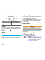
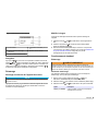
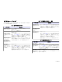
Specifications
Specifications are subject to change without notice.
Specification Details
Dimensions 35 x 20 x 11 cm (13.78 x 7.87 x 4.33 in.)
Weight 1100 g (2.43 lb)
Meter enclosure IP42
Power requirements
(external)
100–240 V, 0.4 A, 47-63 Hz
Meter protection class Class II
Storage temperature –15 to +65 °C (5 to +149 °F)
Operating temperature 0 to 40 °C (41 to 104 °F)
Operating humidity < 80% (non-condensing)
Resolution pH: 0.1/0.01/0.001, ORP: 0.1/1 mV, temperature:
0.1 ºC (0.18 ºF)
Measuring error (± 1 digit) pH: ≤ 0.002, ORP: ≤ 0.2 mV, temperature: ≤ 0.2 ºC
(≤ 0.36 ºF)
Reproducibility (± 1 digit) pH: ± 0.001, ORP: ± 0.1 mV, temperature: ± 0.1 ºC
(± 0.18 ºF)
Data storage 330 results and last 9 calibrations
Connections Combined or indicator probe: BNC connector (Imp.
>10
12
Ω); Reference electrode: banana connector;
A.T.C. type Pt 1000: banana or telephonic
connector; magnetic stirrer: RCA connector
RS232C for printer or PC: telephonic connector;
external PC keyboard: mini DIN connector
Temperature correction Manual, Pt 1000 temperature probe (A.T.C.), NTC
10 kΩ probe
Isopotential pH programmable, standard value 7.00
Measurement display lock Continuous measurement, by stability and by time
Specification Details
Display Liquid crystal, backlit, 128 x 64 dots
Keyboard PET with protective treatment
Certification CE
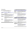
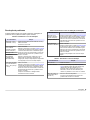
General information
Revised editions are found on the manufacturer’s website.
Safety information
N O T I C E
The manufacturer is not responsible for any damages due to misapplication or
misuse of this product including, without limitation, direct, incidental and
consequential damages, and disclaims such damages to the full extent permitted
under applicable law. The user is solely responsible to identify critical application
risks and install appropriate mechanisms to protect processes during a possible
equipment malfunction.
Please read this entire manual before unpacking, setting up or operating
this equipment. Pay attention to all danger and caution statements.
Failure to do so could result in serious injury to the operator or damage
to the equipment.
Make sure that the protection provided by this equipment is not impaired.
Do not use or install this equipment in any manner other than that
specified in this manual.
Use of hazard information
D A N G E R
Indicates a potentially or imminently hazardous situation which, if not avoided, will
result in death or serious injury.
W A R N I N G
Indicates a potentially or imminently hazardous situation which, if not avoided,
could result in death or serious injury.
English 3

C A U T I O N
Indicates a potentially hazardous situation that may result in minor or moderate
injury.
N O T I C E
Indicates a situation which, if not avoided, may cause damage to the instrument.
Information that requires special emphasis.
Precautionary labels
Read all labels and tags attached to the instrument. Personal injury or
damage to the instrument could occur if not observed. A symbol, if noted
on the instrument, will be included with a danger or caution statement in
the manual.
This symbol, if noted on the instrument, references the instruction
manual for operation and/or safety information.
Electrical equipment marked with this symbol may not be disposed of
in European public disposal systems after 12 August of 2005. In
conformity with European local and national regulations (EU Directive
2002/98/EC), European electrical equipment users must now return
old or end-of-life equipment to the Producer for disposal at no charge
to the user.
Note: For return for recycling, please contact the equipment producer or supplier
for instructions on how to return end-of-life equipment, producer-supplied
electrical accessories, and all auxillary items for proper disposal.
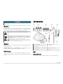
Product overview
The sensION
™
+ meters are used with probes to measure various
parameters in water.
The sensION
™
+ PH31 meter measures pH, ORP (mV) or temperature.
Measurement data can be stored and transferred to a printer or PC.
Product components
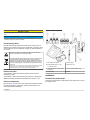
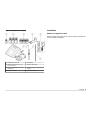
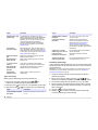
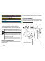
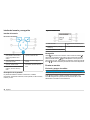
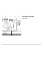
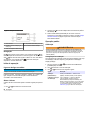
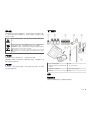
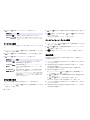
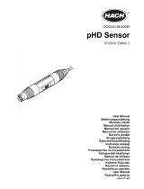
Refer to Figure 1 to make sure that all components have been received.
If any items are missing or damaged, contact the manufacturer or a
sales representative immediately.
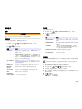
Figure 1 Meter components
1 Electrolyte for the probe 5 Power supply
2 Buffer solutions (pH 4.01, pH
7.00 and pH 10.01)
6 Rod with o-ring
3 Calibration beakers (with magnetic
bar inside)
7 Probe (included with kits only)
4 Probe holder 8 Meter
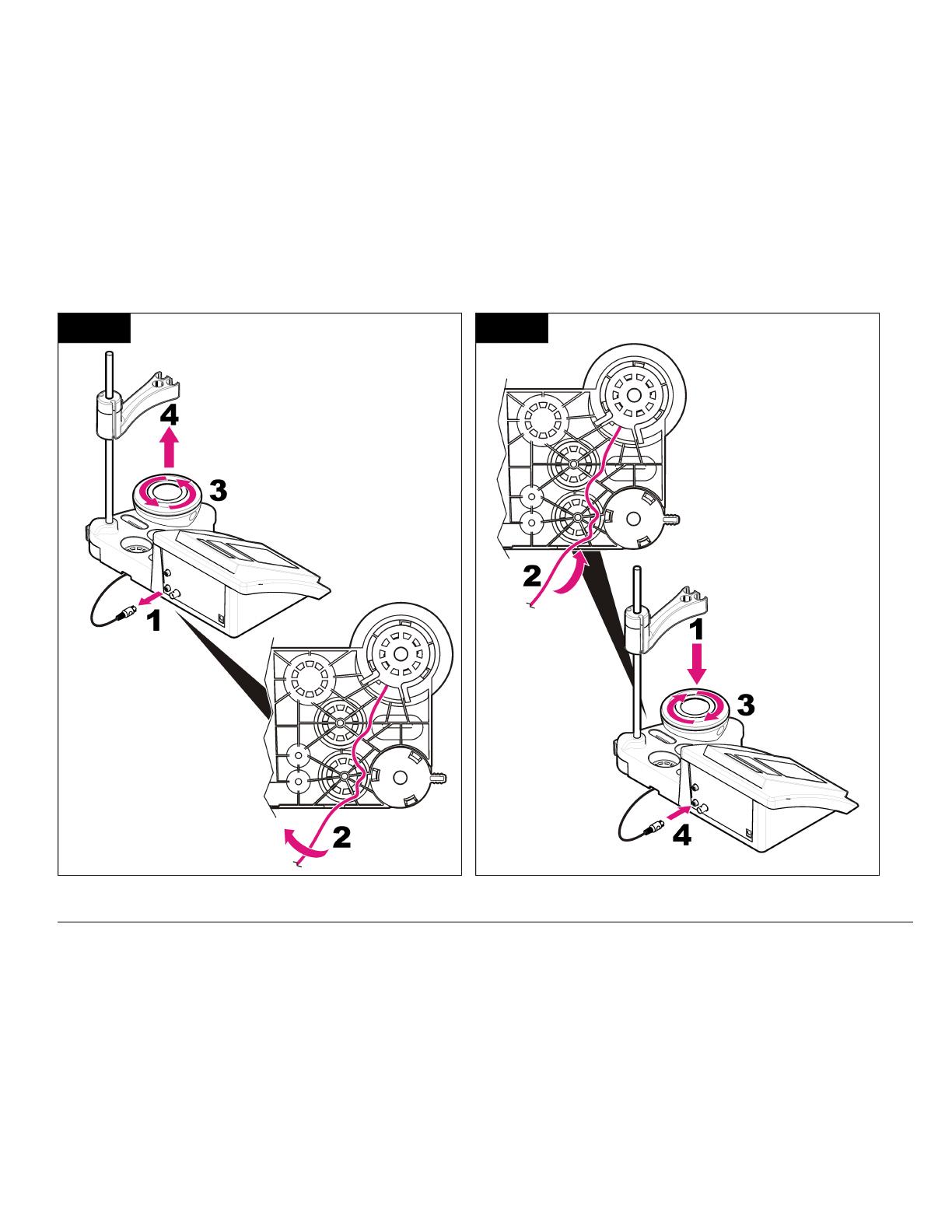
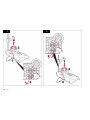
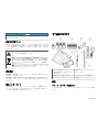
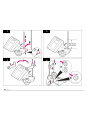
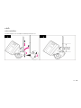
Installation
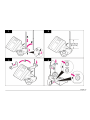
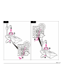
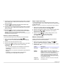
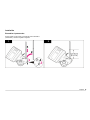
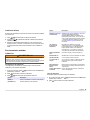
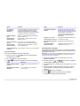
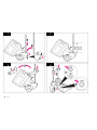
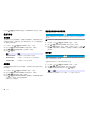
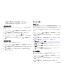
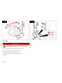
Assemble the probe holder
Follow the numbered steps to assemble the probe holder and to connect
the magnetic stirrer.
4 English

1 2
3 4
English 5

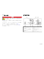
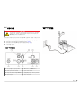
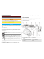
Connect to AC power
D A N G E R
Electrocution hazard. If this equipment is used outdoors or in
potentially wet locations, a Ground Fault Circuit Interrupt (GFCI/GFI)
device must be used to connect the equipment to its main power
source.
The meter can be powered by AC power with the universal power
adapter.
1. Select the correct adapter plug for the power outlet from the adapter
kit.
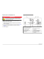
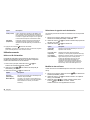
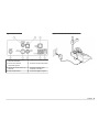
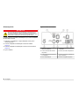
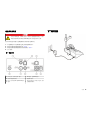
2. Connect the universal power adapter to the meter (Figure 2).
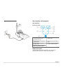
3. Connect the universal power adapter to an AC receptacle (Figure 3).
4. Turn the meter on.
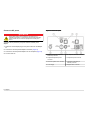
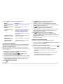
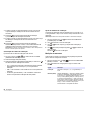
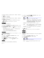
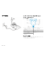
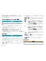
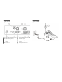
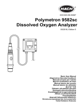
Figure 2 Connector panel
1 Reference electrode (separated
electrodes) connector
5 PC keyboard, mini DIN connector
2 Separated temperature probe
connector
6 Temperature probe connector
3 RS-232 for printer or PC connector 7 Combined pH electrode (or
indicator) connector
4 Power supply 8 Magnetic stirrer connector
6 English

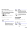
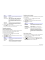
Figure 3 AC power connection
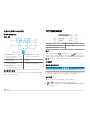
User interface and navigation
User interface
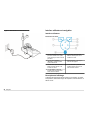
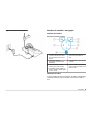
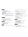
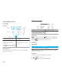
Keypad description
1 RETURN key: cancel or exit the
current menu screen to the
previous menu screen
5 DOWN key: scroll to other options,
change a value
2 MEASUREMENT key: confirm the
selected option
6 ON/OFF: turn on or turn off the
meter
3 UP key: scroll to other options,
change a value
7 LEFT key: change the measuring
unit, enter numbers and letters
4 RIGHT key: change the measuring
unit, enter numbers and letters
Display description
The meter display shows the concentration, units, temperature,
calibration status, operator ID, sample ID, date and time.
English 7

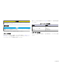
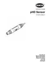
Figure 4 Single screen display
1 Sample ID 4 Sample temperature (ºC or ºF)
2 Measurement unit and value (pH,
ORP (mV))
5 Visual measurement timer
3 Measurement mode or time and
date
Navigation
Use the to return to the previous menu. Use the measure key to
take a sample measurement or to confirm options. Use the arrow keys
to scroll to other options or to change a value. To change the
parameters use the arrow keys and . Refer to each task for specific
instructions.
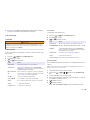
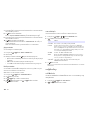
Start-up
Turn the meter on and off
N O T I C E
Make sure that the probe is connected to the meter before the meter is turned on.
Push to turn on or turn off the meter. If the meter does not turn on,
make sure that the AC power supply is properly connected to an
electrical outlet.
Change the language
The display language is selected when the meter is powered on for the
first time.
1. Use the
or to select a language from a list.
2. Confirm with . The measurement screen shows DATA OUTPUT.
3. Select Deactivated if no printer or PC is connected and confirm.
Refer to Select the data output on page 11 for more information
about Data Output.
Standard operation
Calibration
W A R N I N G
Chemical exposure hazard. Obey laboratory safety procedures and wear all of
the personal protective equipment appropriate to the chemicals that are handled.
Refer to the current material safety data sheets (MSDS) for safety protocols.
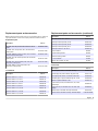
Calibration settings
The calibration settings contain Calibration type, Calibration frequency
and Display options.
1. From the main menu use the or to select CALIBRATION.
Confirm.
2. Use the to enter the calibration menu.
3. Use the or to select the following options:
Option Description
Stability C.: Criterion by stability—select Fast, Standard or Strict.
Calibration type Calibration type—select Technical buffers,
DIN19266 Buffers, User Buffers, To a X value, data
introduction or Theoretical calibration. Refer to
Calibration types for more information.
8 English

Option Description
Cal. frequency Calibration reminder—can be set between 0–7 days
(default daily). The display shows the remaining time to
the new calibration. Refer to Set the calibration reminder
on page 10 for more information.
Display mV Display mV—select YES or NO to show mV.
Standard 220 mV Standard 220 mV—calibrate with a 220 mV standard
solution
To a X value To a X value—use a specific standard solution. Adjust
the value during the calibration.
Data introduction Data introduction Compensation—enter the
compensation value
Factory adjust Factory adjust—enter the compensation value
Calibration types
Different calibration types can be selected.
1. From the main menu use the or to select CALIBRATION.
Confirm.
2. Use the to enter the calibration menu.
3. Use the or to select Calibration type.
Option Description
Technical buffers pH 2.00, 4.01, 7.00, 9.21 and 10.01 at 25 °C
(77 °F)
DIN19266 Buffers pH 1.679, 4.006, 6.865, 7.000, 9.180, 10.012 and
12.454
User Buffers Selected when the technical or DIN19266 buffers
are not used. Refer to Technical buffer solutions
(DIN 19267) on page 18 for pH values of
specific buffer sets at varying temperatures.
Calibration to a X value To adjust manually any scale value of the
measured pH.
Option Description
Data introduction Manual probe constant introduction.
Theoretical calibration The probe calibration data is replaced at 25 °C
(77 °F).
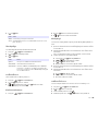
Calibration procedure
This procedure is for general use with liquid calibration solutions. Refer
to the documents that are included with each probe for additional
information.
Note: Solutions should be stirred during calibration. For more information about the
stirring settings, refer to Change the stirring settings on page 12.
1. Pour the buffers or calibration solutions into the labeled calibration
beakers.
2. From the main menu use the or and and to select the
CALIBRATION parameter. Confirm.
3. If required select the Operator ID (1 to 10) and confirm.
4. Rinse the probe with deionized water and put the probe into the first
calibration beaker. Be sure that there are no air bubbles in the
membrane.
5. Push to Start calibration.
6. Push to measure the first calibration solution.
The next calibration solution is shown.
7. Rinse the probe with deionized water and put the probe into the
second calibration beaker. Be sure that there are no air bubbles in
the membrane.
8. Push to measure the second calibration solution.
The next calibration solution is shown.
9. Rinse the probe with deionized water and put the probe into the third
calibration beaker. Be sure that there are no air bubbles in the
membrane.
10. Push to measure the third calibration solution.
When the calibration is good, the display briefly shows Calibration
OK and then returns to the main menu.
Note: When a printer is connected the print menu opens and the result can be
printed.
English 9

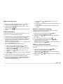
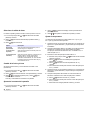
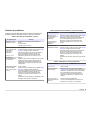
View the calibration data
Data from the most recent calibration can be shown.
1. From the main menu use the or to select DATA LOGGER.
Confirm.
2. Select Display data.
3. Select Calibration data and confirm with . The last calibration data
is shown.
• pH-the slope and offset values are shown alternating with the
deviation (in %) and calibration temperature.
•
ORP-the measured mV value and calibration temperature are
shown.
• Conductivity-the cell constant and calibration temperature for each
standard are shown.
Set the calibration reminder
The calibration reminder can be set between 0 to 23 hours or 1-7 days
(default 1 day). The display shows the remaining time to the new
calibration.
Note: When 0 days is selected, the calibration reminder is turned off.
1. From the main menu use the
or to select CALIBRATION.
Confirm.
2. Use the to enter the calibration menu.
3. Use the or to select Cal. frequency and confirm.
4. Use the and to advance to the next step and use the or to
change a value. Confirm.
Push to start the calibration.
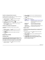
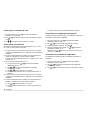
Sample measurements
Each probe has specific preparation steps and procedures for taking
sample measurements.
1. From the main menu use the or and and to select
MEASURE. Confirm.
2. Use the to change the following settings. Confirm every entry.
Option Description
Resolution Select the resolution: 1, 0.1, 0.01 (default) or 0.001
Measure Stability—select By stability Criterion: Fast (variation <
0.02 pH in 6 s), Standard (variation < 0.01 pH in 6 s) or Strict
(variation < 0.002 pH in 6 s). In continuous—enter the time
interval for the In continuous Acquis. interval (data storage or
printing data). By time—enter the time interval for data storage
or printing data.
Display mV Display mV—select YES or NO to show mV.
Limits Limits—select YES or NO. YES: Enter the upper and lower
limits. An acoustic warning appears when the measurement is
out of limit. The report output shows an A next to the
measured value when the measurement was out of limit.
Isopotential Isopotential—change the Isopotential pH value in Data
introduction. Select Calculate to calibrate the probe again.
3. Push to start the measurement.
Note: If the measurement is not stabilizing after 120 seconds, the meter turns
automatically into the continuous measurement mode.
Advanced operation
Use a sample ID
The sample ID tag is used to associate readings with a particular sample
location. If assigned, stored data will include this ID.
1. From the main menu use the or to select SYSTEM. Confirm.
2. Use the or to select Sample ID and confirm.
10 English

3. Use the or to select
Option Description
Automatic A consecutive number will be automatically assigned to every
sample.
Manual A keyboard or a barcode scanner is required to enter the
sample ID name before taking a measurement (maximum
15 characters).
Select the data output
Data can be stored or transferred to a printer or to a PC.
1. From the main menu use the or to select SYSTEM. Confirm.
2. Use the or to select Data Output and confirm.
3. Use the or to select
Option Description
Deactivated Select Deactivated if no printer or PC is connected.
For Printer Select Dot matrix printer or Thermal printer.
For Computer Select Terminal, LabCom or LabCom Easy. The LabCom
Software controls several modules, pH and conductivity
meters, automatic burettes, Samplers and so on from a
computer. The LabCom Easy software gets pH and
conductivity data from a PC.
Change the date and time
The date and time can be changed from the Date / Time menu.
1. From the main menu use the or to select SYSTEM. Confirm.
2. Use the or to select Date / Time and confirm.
3. Use the and to advance to the next step and use the or to
change a value. Confirm.
The current date and time will be shown on the display.
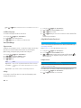
Adjust the display contrast
1. From the main menu use the or to select SYSTEM. Confirm.
2. Use the or to select Display contrast and confirm.
3. Use the and to adjust the contrast of the display and confirm.
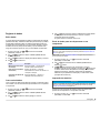
Adjust the temperature
The temperature measurement can be adjusted at 25 °C (77 °F) and/or
85 °C (185 °F) to increase accuracy.
1. Put the probe and a reference thermometer in a container of water at
approximately 25 °C and allow the temperature to stabilize.
2. Compare the temperature read by the meter with that of the
reference thermometer. The difference is the adjustment value for
the meter.
Example: reference thermometer: 24.5 °C; meter: 24.3 °C.
Adjustment value: 0.2 °C.
3. Enter the adjustment value for the 25 °C reading:
a. From the main menu use the or to select SYSTEM. Confirm.
b. Use the or to select Readjust temp. and confirm.
c. Use the or to select 25 °C and confirm.
d. Use the arrow keys to enter the adjustment value for 25 °C.
Confirm.
4. Put the probe and a reference thermometer in a container of water at
approximately 85 °C and allow the temperature to stabilize.
5. Compare the temperature from the meter with that of the reference
thermometer. The difference is the adjustment value for the meter.
a. Use the or to select 85 °C and confirm.
b. Use the arrow keys to enter the adjustment value for 85 °C.
Confirm.
c. Select Save changes and confirm.
English 11

Change the stirring settings
The magnetic stirrer can be turned on and the stirring speed can be
changed in the Stirring menu.
1. From the main menu use the or to select SYSTEM. Confirm.
2. Use the or to select Stirring and confirm.
3. To turn on/off the stirrer push .
4. When the stirrer is turned on, use the or to change the stirring
speed in %.
Note: Use the or to change the stirring speed during calibration and
during a measurement.
Change the temperature units
The temperature units can be changed to Celsius or Fahrenheit.
1. From the main menu use the or to select SYSTEM. Confirm.
2. Use the or to select Temperature units and confirm.
3. Use the or to select between Celsius or Fahrenheit and confirm.
Data logger
Display data
The Display data log contains Measurement data, Electrode report and
Calibration data. The stored data can be send to a printer or to a PC.
When the data log becomes full (400 data points), the oldest data point
is deleted when a new data point is added.
1. From the main menu use the or to select SYSTEM. Confirm.
2. Use the or to select DATA LOGGER and confirm.
3. Use the or to select Display data and confirm.
4. Use the or to select
Option Description
Measurement data Measurement data—stores automatically each time a
sample is measured
Electrode report Electrode report—stores automatically the electrode
history and measurement conditions
Calibration data Calibration data—stores automatically the current
calibration
Delete data
The entire measurement data or electrode report log can be deleted to
remove data that has already been sent to a printer or PC.
1. From the main menu use the or to select SYSTEM. Confirm.
2. Use the or to select DATA LOGGER and confirm.
3. Use the or to select Erase and confirm.
4. Use the or to select Measurement data or Electrode report and
confirm. Confirm again to delete the data.
The entire log is deleted at once.
Send data to a printer or to a computer
N O T I C E
The data output (printer or PC) needs to be selected first, so that the Print menu
is available (refer to Select the data output on page 11).
Note: Refer to Report output on page
13 to select the report output type.
1. From the main menu use the
or to select SYSTEM. Confirm.
2. Use the or to select DATA LOGGER and confirm.
3. Use the or to select Print and confirm. Select one of the
following options and confirm with to print the data: Measurement
data, Electrode data, Calibration data, Calibration report or
Instrument condit.
12 English

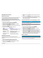
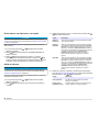
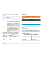
Report output
N O T I C E
The data output (printer or PC) needs to be selected first, so that the Type of
report menu is available (refer to Select the data output on page 11).
Different report output types can be selected when a printer or a PC is
connected.
1. From the main menu use the or to select SYSTEM. Confirm.
2. Use the or to select Type of report and confirm.
3. When a printer or a computer and Terminal is connected, use the
or to select
Option Description
Reduced Select Several or One sample as an output format
Standard Select Several or One sample as an output format. Select
several: Users: The user name appears on the printed report
(17 characters).
Header:The company name can be added as a
header (40 characters) and appears on the print report. Identify
sensor:The sensor model and the sensor serial number can be
added and appears on the print report.
GLP Select Several or One sample as an output format. Select
several: Users: The user name appears on the printed report
(17 characters). Header:The company name can be added as a
header (40 characters) and appears on the print report. Identify
sensor:The sensor model and the sensor serial number can be
added and appears on the print report.
4. When a computer is connected and LabCom Easy (refer to Select
the data output on page 11 for more information) is selected, use the
or to select
Option Description
Users The user name appears on the printed report
(17 characters).
Identify sensor The sensor model and the sensor serial number can be
added and appears on the print report.
Maintenance
W A R N I N G
Multiple hazards. Do not disassemble the instrument for maintenance or service.
If the internal components must be cleaned or repaired, contact the
manufacturer.
C A U T I O N
Personal injury hazard. Only qualified personnel should conduct the tasks
described in this section of the manual.
Clean the instrument
N O T I C E
Never use cleaning agents such as turpentine, acetone or similar products to
clean the instrument including the display and accessories.
Clean the exterior of the instrument with a moist cloth and a mild soap
solution.
Clean the probe
Clean the probe as needed. Refer to Troubleshooting on page 16 for
more information about cleaning. Refer to the probe documentation for
information about the probe maintenance.
Use the cleaning agents listed in Table 1 for contaminations on the pH
probe.
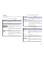
Table 1 Cleaning agents for the pH probe
Contamination Cleaning agent
Proteins Pepsin cleaning solution
Grease, oils, fats Electrode cleaning solution
Limescale 0.1 N HCl solution
English 13

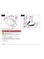
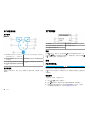
Replace the magnetic stirrer
If the magnetic stirrer does not start, follow the numbered steps to
replace the magnetic stirrer.
14 English
1 2
English 15

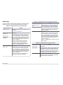
Troubleshooting
Refer to the following table for common problem messages or
symptoms, possible causes and corrective actions.
Table 2 Calibration warnings and errors
Error/Warning Solution
Asymmetry >
58 mV
Slope out of range (accepted values ± 58 mV).
Calibrate again.
Connect a new probe.
Buffer or electrode
in poor conditions.
Calibrate again.
Examine the probe: Clean the probe (refer to Clean the
probe on page 13 for more information); make sure that
there are no air bubbles in the membrane. Shake the probe
like a thermometer; Connect a different probe to verify if
problem is with probe or meter.
Examine the buffer solution: Make sure that the buffer used
matches the buffer specified in configuration; make sure of
the temperature specification in configuration; use new
buffer solution.
Sens. (a) < 70%
BUFFER NOT
RECOGNIZED
UNSTABLE
READING
Time t> 100 s
Calibrate again.
Examine the probe: Clean the probe (refer to Clean the
probe on page 13 for more information); make sure that
there are no air bubbles in the membrane. Shake the probe
like a thermometer; connect a different probe to verify if
problem is with probe or meter.
Make sure that the membrane and the diaphragm are
properly immersed in the sample.
Table 2 Calibration warnings and errors (continued)
Error/Warning Solution
Electrode in poor
conditions.
Examine the probe: Clean the probe (refer to Clean the
probe on page 13 for more information); make sure that
there are no air bubbles in the membrane. Shake the probe
like a thermometer; connect a different probe to verify if
problem is with probe or meter.
Check the
electrode
SAME BUFFERS Calibrate again.
Examine the probe: Clean the probe (refer to Clean the
probe on page 13 for more information); make sure that
there are no air bubbles in the membrane. Shake the probe
like a thermometer; connect a different probe to verify if
problem is with probe or meter.
Examine the buffer solution: Use new buffer solution.
Table 3 Measurement warnings and errors
Error/Warning Solution
pH 12.78 19°C Calibrate again
pH out of range Examine the probe: Clean the probe (refer to Clean the
probe on page 13 for more information); make sure that
there are no air bubbles in the membrane. Shake the
probe like a thermometer; connect a different probe to
verify if problem is with probe or meter.
Temp out of range
°C
Examine the temperature sensor.
Connect a different probe to verify if problem is with probe
or meter.
Time > 60 s Make sure that the membrane and the diaphragm are
properly immersed in the sample.
Examine the temperature.
Examine the probe: Clean the probe (refer to Clean the
probe on page 13 for more information); make sure that
there are no air bubbles in the membrane. Shake the
probe like a thermometer; connect a different probe to
verify if problem is with probe or meter.
Time > 150 s
Time > 300 s
16 English

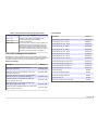
Replacement parts and accessories
Note: Product and Article numbers may vary for some selling regions. Contact the
appropriate distributor or refer to the company website for contact information.
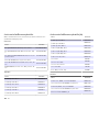
Replacement parts
Description Item no.
sensION+ PH3 Lab pH-meter with accessories, without
probe
LPV2000.97.0002
sensION+ PH31 Lab pH-meter, GLP, with accessories,
without probe
LPV2100.97.0002
sensION+ MM340 Lab pH & Ion-meter, GLP, 2 channels,
with accessories, without probe
LPV2200.97.0002
sensION+ EC7 Lab conductivity meter, with accessories,
without probe
LPV3010.97.0002
sensION+ EC71 Lab conductivity meter, GLP, with
accessories, without probe
LPV3110.97.0002
sensION+ MM374, 2 channel Lab meter, GLP,
accessories, without probes
LPV4110.97.0002
Consumables
Description Item no.
pH buffer solution 4.01, 125 mL LZW9460.99
pH buffer solution 7.00, 125 mL LZW9461.97
pH buffer solution 10.01, 125 mL LZW9470.99
pH buffer solution 4.01, 250 mL LZW9463.99
pH buffer solution 7.00, 250 mL LZW9464.97
pH buffer solution 10.01, 250 mL LZW9471.99
pH buffer solution 4.01, 1000 mL LZW9466.99
pH buffer solution 7.00, 1000 mL LZW9467.97
Replacement parts and accessories (continued)
Description Item no.
pH buffer solution 10.01, 1000 mL LZW9472.99
Electrolytic solution (KCl 3M), 125 mL LZW9510.99
Electrolytic solution (KCl 3M), 250 mL LZW9500.99
Electrolytic solution (KCl 3M), 50 mL LZW9509.99
Electrolytic solution 0.1 M, 125 mL LZW9901.99
Enzyme solution 2964349
Pepsin Cleaning Solution 2964349
Electrode cleaning solution 2965249
0.1 N HCl solution 1481253
Ethanol, 95% (Grease, oils, fats) 2378900
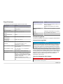
Accessories
Description Item no.
Thermal printer, RS232, for sensION+ benchtop LZW8201.99
Thermal paper for printer LZW8201, bag with 5 rolls LZW9117.99
Dot-impact printer, RS232, for sensION+ instruments LZW8200.99
Standard paper for printer LZW8200, bag with 10 rolls LZW9000.99
Ribbon for printer LZW8200, 3 units LZW9001.99
LabCom Easy PC SW, for sensION+ GLP, CD, cable,
USB adapter
LZW8997.99
LabCom PC SW, for sensION+ GLP, CD, cable, USB
adapter
LZW8999.99
RS232 cable, for sensION+ benchtop instruments LZW9135.99
RS232 cable for sensION+ benchtop, with USB adapter LZW9135USB.99
English 17

Replacement parts and accessories (continued)
Description Item no.
Magnetic stirrer with sensor holder, for sensION+ MM
benchtop
LZW9319.99
3x50 mL printed beakers for benchtop pH calibration LZW9110.97
Three-sensor holder, for sensION+ benchtop instruments LZW9321.99
Holder and clamp for three sensors LZW9155.99
Pyrex glass chamber, continuous flow measurements LZW9118.99
PP protector, electrode storage LZW9161.99
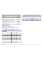
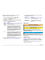
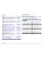
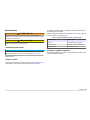
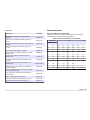
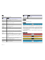
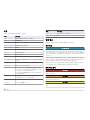
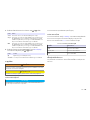
Standard solutions
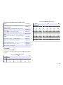
Technical buffer solutions (DIN 19267)
Refer to Table 4 pH and ORP (mV) values of specific buffer sets at
varying temperatures.
Table 4 pH, ORP (mV) and temperature values
Temperature pH mV
°C °F
0 32 2.01 4.01 7.12 9.52 10.30 —
10 50 2.01 4.00 7.06 9.38 10.17 245
20 68 2.00 4.00 7.02 9.26 10.06 228
25 77 2.00 4.01 7.00 9.21 10.01 220
30 86 2.00 4.01 6.99 9.16 9.96 212
40 104 2.00 4.03 6.97 9.06 9.88 195
50 122 2.00 4.06 6.97 8.99 9.82 178
60 140 2.00 4.10 6.98 8.93 9.76 160
70 158 2.01 4.16 7.00 8.88 — —
Table 4 pH, ORP (mV) and temperature values (continued)
Temperature pH mV
°C °F
80 176 2.01 4.22 7.04 8.83 — —
90 194 2.01 4.30 7.09 8.79 — —
18 English

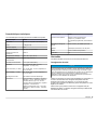
Caractéristiques techniques
Les caractéristiques techniques peuvent être modifiées sans préavis.
Caractéristiques Détails
Dimensions 35 x 20 x 11 cm (13,78 x 7,87 x 4,33 po)
Poids 1 100 g (2,43 lb)
Boîtier de l'appareil IP42
Alimentation (externe) 100–240 V, 0,4 A, 47-63 Hz
Classe de protection de
l'instrument
Classe II
Température de stockage –15 à +65 °C (5 à +149 °F)
Température de
fonctionnement
0 à 40 °C (41 à 104 °F)
Humidité de fonctionnement < 80 % (sans condensation)
Résolution pH : 0,1/0,01/0,001, ORP : 0,1/1 mV,
température : 0,1 ºC (0,18 ºF)
Erreur de mesure (± 1 chiffre) pH : ≤ 0,002, ORP : ≤ 0,2 mV, température : ≤
0,2 ºC (≤ 0,36 ºF)
Reproductibilité (± 1 chiffre) pH : ± 0,001, ORP : ± 0,1 mV, température : ±
0,1 ºC (± 0,18 ºF)
Stockage des données 330 résultats et 9 derniers étalonnages
Connexions Sonde d'indicateur ou combinée : connecteur
BNC (imp. > 10
12
Ω) ; électrode de référence :
connecteur banane ; type A.T.C. Pt 1000 :
connecteur banane ou téléphonique ; agitateur
magnétique : connecteur RCA
RS232C pour imprimante ou PC : connecteur
téléphonique ; clavier PC externe : connecteur
mini-DIN
Caractéristiques Détails
Correction de température Manuelle, sonde de température Pt
1000 (A.T.C.), sonde NTC 10 kΩ
pH isopotentiel programmable, valeur standard
7,00
Verrouillage d'affichage de
mesure
Mesure continue, par stabilité et par durée
Afficheur Cristal liquide, rétroéclairé, 128 x 64 points
Clavier PET avec traitement de protection
Certification CE
Généralités
Les éditions révisées se trouvent sur le site Internet du fabricant.
Consignes de sécurité
A V I S
Le fabricant décline toute responsabilité quant aux dégâts liés à une application
ou un usage inappropriés de ce produit, y compris, sans toutefois s'y limiter, des
dommages directs ou indirects, ainsi que des dommages consécutifs, et rejette
toute responsabilité quant à ces dommages dans la mesure où la loi applicable le
permet. L'utilisateur est seul responsable de la vérification des risques
d'application critiques et de la mise en place de mécanismes de protection des
processus en cas de défaillance de l'équipement.
Veuillez lire l'ensemble du manuel avant le déballage, la configuration ou
la mise en fonctionnement de cet appareil. Respectez toutes les
déclarations de prudence et d'attention. Le non-respect de cette
procédure peut conduire à des blessures graves de l'opérateur ou à des
dégâts sur le matériel.
Assurez-vous que la protection fournie avec cet appareil n'est pas
défaillante. N'utilisez ni n'installez cet appareil d'une façon différente de
celle décrite dans ce manuel.
Français 19

Interprétation des indications de risques
D A N G E R
Indique une situation de danger potentiel ou imminent qui, si elle n'est pas évitée,
entraîne des blessures graves, voire mortelles.
A V E R T I S S E M E N T
Indique une situation de danger potentiel ou imminent qui, si elle n'est pas évitée,
peut entraîner des blessures graves, voire mortelles.
A T T E N T I O N
Indique une situation de danger potentiel qui peut entraîner des blessures
mineures ou légères.
A V I S
Indique une situation qui, si elle n'est pas évitée, peut occasionner
l'endommagement du matériel. Informations nécessitant une attention
particulière.
Etiquettes de mise en garde
Lire toutes les informations et toutes les étiquettes apposées sur
l’appareil. Des personnes peuvent se blesser et le matériel peut être
endommagé si ces instructions ne sont pas respectées. Si un symbole
‘danger’ ou ‘attention’ se trouve sur l’instrument, une explication est
indiquée dans le manuel.
Si l'appareil comporte ce symbole, reportez-vous au manuel
d'utilisation pour consulter les informations de fonctionnement et de
sécurité.
En Europe, depuis le 12 août 2005, les appareils électriques
comportant ce symbole ne doivent pas être jetés avec les autres
déchets. Conformément à la réglementation nationale et européenne
(Directive 2002/98/CE), les appareils électriques doivent désormais
être, à la fin de leur service, renvoyés par les utilisateurs au fabricant,
qui se chargera de les éliminer à ses frais.
Remarque : Pour le retour à des fins de recyclage, veuillez contactez le fabricant
ou le fournisseur d'équipement afin d'obtenir les instructions sur la façon de
renvoyer l'équipement usé, les accessoires électriques fournis par le fabricant, et
tous les articles auxiliaires pour une mise au rebut appropriée.
Présentation du produit
Les appareils de mesure de la série ION
™
+ s'utilisent avec des sondes
pour mesurer différents paramètres dans l'eau.
L'appareil de mesure sensION
™
+ PH31 mesure le pH, l'ORP (mV) et la
température. Les données de mesure peuvent être enregistrées et
transférées vers une imprimante ou un PC.
Composants du produit
Consultez la Figure 1 pour vous assurer que tous les éléments ont bien
été reçus. Si des éléments manquent ou sont endommagés, contactez
immédiatement le fabricant ou un représentant commercial.
20 Français
A página está carregando ...
A página está carregando ...
A página está carregando ...
A página está carregando ...
A página está carregando ...
A página está carregando ...
A página está carregando ...
A página está carregando ...
A página está carregando ...
A página está carregando ...
A página está carregando ...
A página está carregando ...
A página está carregando ...
A página está carregando ...
A página está carregando ...
A página está carregando ...
A página está carregando ...
A página está carregando ...
A página está carregando ...
A página está carregando ...
A página está carregando ...
A página está carregando ...
A página está carregando ...
A página está carregando ...
A página está carregando ...
A página está carregando ...
A página está carregando ...
A página está carregando ...
A página está carregando ...
A página está carregando ...
A página está carregando ...
A página está carregando ...
A página está carregando ...
A página está carregando ...
A página está carregando ...
A página está carregando ...
A página está carregando ...
A página está carregando ...
A página está carregando ...
A página está carregando ...
A página está carregando ...
A página está carregando ...
A página está carregando ...
A página está carregando ...
A página está carregando ...
A página está carregando ...
A página está carregando ...
A página está carregando ...
A página está carregando ...
A página está carregando ...
A página está carregando ...
A página está carregando ...
A página está carregando ...
A página está carregando ...
A página está carregando ...
A página está carregando ...
A página está carregando ...
A página está carregando ...
A página está carregando ...
A página está carregando ...
A página está carregando ...
A página está carregando ...
A página está carregando ...
A página está carregando ...
A página está carregando ...
A página está carregando ...
A página está carregando ...
A página está carregando ...
A página está carregando ...
A página está carregando ...
A página está carregando ...
A página está carregando ...
A página está carregando ...
A página está carregando ...
A página está carregando ...
A página está carregando ...
A página está carregando ...
A página está carregando ...
A página está carregando ...
A página está carregando ...
A página está carregando ...
A página está carregando ...
A página está carregando ...
A página está carregando ...
A página está carregando ...
A página está carregando ...
A página está carregando ...
A página está carregando ...
A página está carregando ...
A página está carregando ...
A página está carregando ...
A página está carregando ...
A página está carregando ...
A página está carregando ...
A página está carregando ...
A página está carregando ...
A página está carregando ...
A página está carregando ...
A página está carregando ...
A página está carregando ...
A página está carregando ...
A página está carregando ...
A página está carregando ...
A página está carregando ...
A página está carregando ...
A página está carregando ...
A página está carregando ...
A página está carregando ...
A página está carregando ...
A página está carregando ...
A página está carregando ...
A página está carregando ...
A página está carregando ...
A página está carregando ...
-
 1
1
-
 2
2
-
 3
3
-
 4
4
-
 5
5
-
 6
6
-
 7
7
-
 8
8
-
 9
9
-
 10
10
-
 11
11
-
 12
12
-
 13
13
-
 14
14
-
 15
15
-
 16
16
-
 17
17
-
 18
18
-
 19
19
-
 20
20
-
 21
21
-
 22
22
-
 23
23
-
 24
24
-
 25
25
-
 26
26
-
 27
27
-
 28
28
-
 29
29
-
 30
30
-
 31
31
-
 32
32
-
 33
33
-
 34
34
-
 35
35
-
 36
36
-
 37
37
-
 38
38
-
 39
39
-
 40
40
-
 41
41
-
 42
42
-
 43
43
-
 44
44
-
 45
45
-
 46
46
-
 47
47
-
 48
48
-
 49
49
-
 50
50
-
 51
51
-
 52
52
-
 53
53
-
 54
54
-
 55
55
-
 56
56
-
 57
57
-
 58
58
-
 59
59
-
 60
60
-
 61
61
-
 62
62
-
 63
63
-
 64
64
-
 65
65
-
 66
66
-
 67
67
-
 68
68
-
 69
69
-
 70
70
-
 71
71
-
 72
72
-
 73
73
-
 74
74
-
 75
75
-
 76
76
-
 77
77
-
 78
78
-
 79
79
-
 80
80
-
 81
81
-
 82
82
-
 83
83
-
 84
84
-
 85
85
-
 86
86
-
 87
87
-
 88
88
-
 89
89
-
 90
90
-
 91
91
-
 92
92
-
 93
93
-
 94
94
-
 95
95
-
 96
96
-
 97
97
-
 98
98
-
 99
99
-
 100
100
-
 101
101
-
 102
102
-
 103
103
-
 104
104
-
 105
105
-
 106
106
-
 107
107
-
 108
108
-
 109
109
-
 110
110
-
 111
111
-
 112
112
-
 113
113
-
 114
114
-
 115
115
-
 116
116
-
 117
117
-
 118
118
-
 119
119
-
 120
120
-
 121
121
-
 122
122
-
 123
123
-
 124
124
-
 125
125
-
 126
126
-
 127
127
-
 128
128
-
 129
129
-
 130
130
-
 131
131
-
 132
132
-
 133
133
-
 134
134


em outros idiomas
- español: Hach sensIONTM+ pH31 Manual de usuario
- français: Hach sensIONTM+ pH31 Manuel utilisateur
- English: Hach sensIONTM+ pH31 User manual
- 日本語: Hach sensIONTM+ pH31 ユーザーマニュアル
Artigos relacionados
-
 Hach sensION MM340 Manual do usuário
-
 Hach sensION+ pH3 Manual do usuário
-
 Hach sensION+ MM374 Manual do usuário
-
 Hach sensION+ EC71 Manual do usuário
-
 Hach sensION+ EC7 Manual do usuário
-
 Hach pHD Sensor Manual do usuário
-
Hach sensION+ EC5 Manual do usuário
-
 Hach Polymetron 9582sc Basic User Manual
-
 Hach pHD Sensor Manual do usuário
-
 Hach sensION+ pH1 Manual do usuário


