Yamaha LS9 Manual do usuário
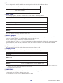
- Categoria
- Equalizadores de áudio
- Tipo
- Manual do usuário
Este manual também é adequado para

LS9 Editor Owner’s Manual
1
Special Notices
•The software and this owner’s manual are the exclu-
sive copyrights of Yamaha Corporation.
•Copying of the software or reproduction of this
manual in whole or in part by any means is expressly
forbidden without the written consent of the manu-
facturer.
•Copying of the commercially available music
sequence data and/or digital audio files is strictly
prohibited except for your personal use.
•Yamaha makes no representations or warranties
with regard to the use of the software and documen-
tation and cannot be held responsible for the results
of the use of this manual and the software.
•The screen displays as illustrated in this owner’s
manual are for instructional purposes, and may
appear somewhat different from the screens which
appear on your computer.
•Future upgrades of application and system software
and any changes in specifications and functions will
be announced separately.
•Windows is a registered trademark of Microsoft
Corporation in the U.S. and other countries.
•Apple, Mac and Macintosh are trademarks of Apple
Inc., registered in the U.S. and other countries.
•The company names and product names in this
Owner’s Manual are the trademarks or registered
trademarks of their respective companies.
❏
Yamaha Pro Audio Global Site
http://www.yamahaproaudio.com/
Contents
Getting Started ......................................... 2
Master window ....................................... 10
Overview window ................................... 13
Custom Fader Layer window .................. 24
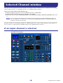
Selected Channel window....................... 26
Library window ....................................... 45
Patch Editor window............................... 48
Rack window ........................................... 52
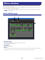
Meter window ......................................... 61
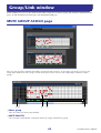
Group/Link window ................................ 64
Scene window ......................................... 67
Custom Fader Layer Setup window ........ 74
User Defined Keys Setup window........... 75
Keyboard Shortcuts................................. 76
Appendix ................................................. 77
*Specifications and descriptions in this owner’s manual are
for information purposes only. Yamaha Corp. reserves the
right to change or modify products or specifications at any
time without prior notice.
LS9 Editor
LS9 Editor
LS9 Editor
Owner’s Manual
Owner’s Manual
Owner’s Manual
Description of menus and buttons
In the event that menu and button names on a Windows
system are different from those on a Mac, this manual
uses the Windows menu and button names followed by the
Mac menu and button names in parentheses.

LS9 Editor Owner’s Manual
2
Overview of LS9 Editor
LS9 Editor enables you to remotely control the Yamaha LS9 mixing console and to save the parameter settings on
your computer. To use LS9 Editor, you must first perform the following operations:
1 Start and configure Studio Manager.
2 Start and configure LS9 Editor.
3 Synchronize LS9 Editor with your LS9 console (
➥
p.8).
For more information on using Studio Manager, refer to the Studio Manager Owner’s Manual.
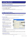
Configuring LS9 Editor
You must configure the following settings for each open Editor.
• Before you make the following settings, you must make settings for the DME-N Network Driver (Windows)
or the Network-MIDI Driver (Mac) and select the MIDI port in the Setup window of Studio Manager.
•To open an editor, double-click the icon for the desired editor in the Studio Manager window.
❏
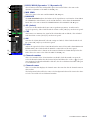
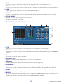
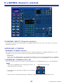
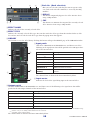
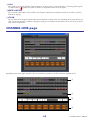
System Setup
To open the System Setup window, choose [System Setup] from the [File] menu.
Be sure to specify the Input port and Output port.
A
Input port/Output port
From the ports you specified in Studio Man-
ager, select the ports that the editor will use
to communicate with the LS9 console.
B
Fast Sync
This allows synchronization to be speed up,
reducing the time required. This check box
enables/disables this function. You should
disable this if synchronization errors occur
while this functions enabled.
C
Window Control from Console
Allows the LS9 Editor windows to be opened
and closed remotely using the USER
DEFINED KEYS of the LS9 console. The
check box enables/disables these operations.
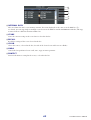
D
Level Meter
By disabling the meter function you can reduce the processing load caused by screen drawing and communica-
tion. This check box enables/disables the level meter function.
E
Confirmation
These check boxes specify whether a confirmation dialog box will be displayed when you store (Store Confirma-
tion), recall (Recall Confirmation), patch (Patch Confirmation), or patch in a way that would affect an existing
patch (Steal Patch Confirmation).
F
Administrator Password
Enter the Administrator password that was specified on the LS9 console. If this password is not entered correctly,
it will not be possible to synchronize from LS9 Editor to the LS9 console.
Getting Started
NOTE
NOTE
NOTE
2
5
6
3
4
1

LS9 Editor Owner’s Manual
3
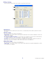
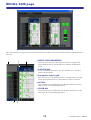
❏
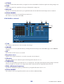
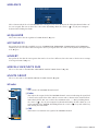
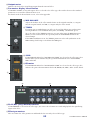
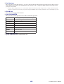
Mixer Setup
To open the Mixer Setup window, choose [Mixer Setup] from the [File] menu.
A
ModelSelect
Here you can specify the model of LS9 console. This is set automatically when the Editor synchronizes with the
LS9 console.
B
Mix Bus Setup
Here you can make settings relating to the MIX buses.
Signal Type:
This specifies whether each two adjacent odd-numbered/even-numbered MIX buses will be used
as MONO x2 or STEREO.
Bus Type/Pre Fader Send Point:
Specifies whether the Send Point of each two adjacent odd-numbered/
even-numbered MIX buses will be VARI (PRE EQ), VARI (PRE FADER), or FIXED.
Pan Link:
This is valid only when the Signal Type is STEREO and the BUS TYPE is VARI; when enabled, the
PAN setting sent to the stereo MIX bus will be linked with the PAN to the STEREO bus.
C
Matrix Bus Setup
Here you can make settings relating to the MATRIX buses.
Signal Type:
This specifies whether each two adjacent odd-numbered/even-numbered MATRIX buses will be
used as MONO x2 or STEREO.
1
2
3

LS9 Editor Owner’s Manual
4
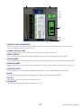
❏
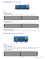
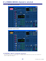
Creating a user key
To open the Create User Key window, choose [Create User Key] from the [File] menu.
This creates a user key (with “.L9U” file name extension) that can be read from a USB storage device by the LS9
console to automatically set user-specific parameters.
A
User Name
Specify the name of the user. You can enter up to eight single-byte characters of alphabet and numerals.
B
Comment
Enter a comment for each user. You can enter up to thirty-two single-byte alphanumeric characters.
C
Password
Enter a password that will be used when this user key is read by the LS9 console. You can enter up to eight single-
byte alphanumeric characters. Uppercase and lowercase are distinguished.
D
Re-Enter Password
Enter the password once again as a safeguard against mistaken entry.
E
POWER USER
Specify whether this user is a power user. Power users can use the LS9 console to create or edit a user authentica-
tion key with a specified user level.
F
Administrator Password
Enter the Administrator password that was specified on the LS9 console. This is not required if no Administrator
password has been specified on the LS9 console, but if this password is incorrect you will be asked to enter it when
the user key is read.
G
ACCESS PERMISSION
In this area, specify the parameters that this user will be allowed to operate.
2 465
1
3
7
8
9
J
K
L
N
O P
M

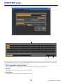
LS9 Editor Owner’s Manual
5
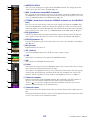
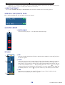
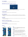
H
CH OPERATION
INPUT, ST IN, MIX, MATRIX, ST/MONO:
Select the channels whose parameters will be operable.
HA:
Change the operating privileges for the head amp gain and phantom power of the selected channels.
PROCESSING:
Change the operating privileges for overall signal processing parameters (except for fader
and [ON] key) of the selected channel. For the specific parameters included in PROCESSING, refer to the
appendix of the LS9 owner’s manual.
FADER/ON:
Change the operating privileges for the pan/balance, fader, channel on, send on/off, and send
level of the selected channels.
Set All:
Turn on HA, PROCESSING, and FADER/ON for all channels.
Clear All:
Turn off HA, PROCESSING, and FADER/ON for all channels.
Set by One Click:
If this button is on, HA, PROCESSING, and FADER/ON will all be turned on when you
select a channel. If all are already on, all will be turned off.
I
SCENE LIST
STORE/SORT:
Change the operating privileges for scene store and sort operations.
RECALL:
Change the operating privileges for scene recall operations.
J
LIBRARY LIST
STORE/CLEAR:
Change the operating privileges for library store and clear operations.
RECALL:
Change the operating privileges for library recall operations.
K
FILE LOAD
USER SETUP:
Change the operating privileges for loading user-defined keys and preferences when loading a
file.
SYSTEM SETUP MONITOR SETUP:
Change the operating privileges for loading system setup and moni-
tor setup settings when loading a file.
CURRENT SCENE:
Change the operating privileges for loading the current scene when loading a file.
SCENE LIST:
Change the operating privileges for loading the scene list when loading a file.
LIBRARY LIST:
Change the operating privileges for loading the library list when loading a file.
L
CURRENT SCENE
INPUT PATCH:
Change the operating privileges for input patch operations.
INPUT NAME:
Change the privileges for editing the input names.
OUTPUT PATCH:
Change the operating privileges for output patching.
OUTPUT NAME:
Change the privileges for editing the output names.
BUS SETUP:
Change the operating privileges for buses.
RACK:
Change the operating privileges for rack operations.
MUTE GROUP ASSIGN:
Change the privileges for assigning mute groups.
MUTE GROUP MASTER: Change the operating privileges for enabling/disabling mute groups.
M MONITOR SETUP
OSCILLATOR: Change the operating privileges for oscillator settings.
TALKBACK: Change the operating privileges for talkback settings.
N SYSTEM SETUP
MIXER SETUP: Change the privileges for making mixer setup settings.
OUTPORT SETUP: Change the privileges for making outport setup settings.
MIDI: Change the privileges for making MIDI settings.
O Create
Creates the user key.
P Cancel
Closes the window.

LS9 Editor Owner’s Manual
6
Working with Sessions
All of your console’s mix settings in LS9 Editor, including Scene and library data, are called Sessions.
The following table describes how to handle Sessions.
When you save a session in the window of an editor, the settings of only that editor will be saved in a file. Session files
saved by LS9 Editor have a filename extension of “.YSE”. Files in which only the LS9 console data is saved (filename
extension “.L9A”) can also be handled, allowing you to use a USB storage device to exchange data with the LS9 con-
sole.
If you save a Session in the Studio Manager window, all selected Editor settings are saved in a file with a file extension
of “.YSM.”
Undo/Redo Function
In LS9 Editor, you can cancel the latest operation (Undo) and also cancel the cancellation of the latest operation
(Redo). If you perform an Undo operation twice in a row, you can cancel the two most-recent operations. If you per-
form an Undo operation three times in a row, you can cancel the three most-recent operations. In this way, you can
cancel multiple recent operations. The following table describes how to use the Undo/Redo function.
Please note, however, that after you perform one of the following operations, you cannot successfully undo or redo
any previous operation:
•Operations on the LS9 console
• Quitting Studio Manager
•Synchronizing with the LS9 console
•Session operations
You cannot Undo or Redo the following operations:
• Edits in the Setup window
• Synchronization
• Opening and closing the windows
• Resizing or moving the windows
There are certain other operations that cannot be undone, depending on the function.
For library or scene operations, Undo/Redo applies only to the single most recent operation. You cannot
undo any operations prior to this. Undo/Redo in these windows is available only using the [UNDO] button
within the respective window. Even if you perform a scene recall from the Master window, you cannot use
a shortcut or menu operation to undo the recall.
Creating a new Session Choose [New Session] from the [File] menu.
Opening a previously saved Session Choose [Open Session] from the [File] menu.
Saving the current Session Choose [Save Session] from the [File] menu.
Saving the current Session with a new name Choose [Save Session As...] from the [File] menu.
Undo Choose [Undo] from the [Edit] menu.
Redo Choose [Redo] from the [Edit] menu.
NOTE
NOTE

LS9 Editor Owner’s Manual
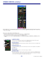
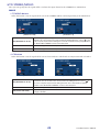
7
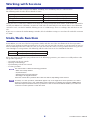
Window operations
You can select and open each window from the [Win-
dows] menu. For the Overview window and Rack win-
dow, use the sub-menu to select the channels or library
you want to see.
You can choose Tile or Cascade to arrange the windows within the editor.
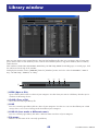
In the Library window or Scene window, click the tabs
located at the top of the window to switch between
pages.
● Cascade
● Tile

LS9 Editor Owner’s Manual
8
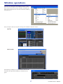
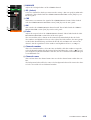
Synchronizing LS9 Editor
When LS9 Editor starts up, the parameter settings on the console and the parameter settings in LS9 Editor may be
different. Therefore, you must first match the parameter settings on the console with those in LS9 Editor. This oper-
ation is called “synchronization.” Follow the steps below to synchronize LS9 Editor.
1 Select [Synchronization], then [Re-synchronize].
The following window opens.
2 Select whether you want to transfer your settings to LS9 Edi-
tor, or vice versa.
At this time, the All Libs option determines whether or not Scene and
Library data is synchronized.
PC ➔ Console: Tr ansfers the current parameter settings in LS9 Editor to your console.
Console ➔ PC: Tr ansfers the current parameter settings of your console to the LS9 Editor.
3 Click [OK].
Do not operate the console while synchronization is in progress.
• If you use the “Total Recall” function in Studio Manager, all selected Editors in Studio Manager are synchronized
with the corresponding devices.
• If you synchronize using PC -> Console, and the console contains data that is set to “read-only,” a dialog box will ask
you whether you want to copy the read-only data to LS9 Editor.
If this data is not copied, console data that is set to read-only status will not be synchronized.
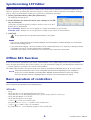
Offline Edit Function
If you do not want to synchronize your console with LS9 Editor, select [Offline Edit] from the [Synchronization]
menu. To apply your off-line edits to your console, select [Re-Synchronize] from the [Synchronization] with the PC
-> Console option to synchronize the console with LS9 Editor.
The Offline Edit function is also activated when you click the [ONLINE]/[OFFLINE] button in the Sync window.
Some effect parameters in the console change their displayed values depending on the sampling fre-
quency. If you switch LS9 Editor from OFFLINE to ONLINE, displayed parameter values may change
because LS9 Editor loads the sampling frequency from the console and updates the display.
Basic operation of controllers
You can operate the controllers in the following ways.
❏ Knobs
•Drag
•Click, and then use the up/down/left/right cursor keys
•Click, and then use the PageUp/PageDown keys (greater change than the cursor keys)
•Click, and then Home sets to far left
•Click, and then End sets to far right
• <Ctrl>(< >)+click sets to default value
For send knobs etc., sets to –∞ regardless of the default value.
• <Ctrl>(< >)+<Shift>+click sets to nominal
For send knobs etc., sets to nominal regardless of the default value.
NOTE
NOTE

LS9 Editor Owner’s Manual
9
❏ Faders
•Drag
•Click, and then use the up/down cursor keys (or left/right cursor keys for horizontal faders)
•Click, and then use the PageUp/PageDown keys (greater change than the cursor keys)
•Click, and then Home sets to maximum value
•Click, and then End sets to minimum value
• <Ctrl>(< >)+click sets to default value
For channel faders etc., sets to –∞ regardless of the default value.
• <Ctrl>(< >)+<Shift>+click sets to nominal
For channel faders etc.,sets to nominal regardless of the default value.
❏ Numerical displays only
•Click and drag up/down
•Click, and then use the up/down cursor keys
•Click, and then use the PageUp/PageDown keys (greater change than the cursor keys)
•Click, and then Home sets to maximum value
•Click, and then End sets to minimum value
• <Ctrl>(< >)+click sets to default value
❏ Bar graphs
•Drag
• <Ctrl>(< >)+click sets to –∞
• <Ctrl>(< >)+<Shift>+click sets to nominal

LS9 Editor Owner’s Manual
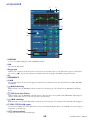
10
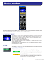
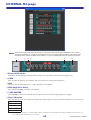
In the Master window you can synchronize settings with the LS9 console, recall scenes, and access the Overview win-
dow. To open this window, choose [Master] from the [Windows] menu, or assign [LS9 EDITOR CONTROL]-[MAS-
TER] to a USER DEFINED KEY on the LS9 console, and execute that function.
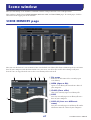
❏ CHANNEL SELECT
This indicates the number and name of the channel to which your operations will apply. To
switch channels, you can either click the [SELECT] button and choose from the list that
appears, or you can click the left/right arrow-shaped channel select buttons. You can use
the channel name text box to edit the name.
This is linked with the [SEL] keys on the LS9 itself.
You can change the icon by right-clicking (<control> key + clicking) it, or change the back-
ground color by left-clicking.
The background color you specify here will also be the background color for the channel
name in the Overview window.
❏ SYNC
This indicates the status of connection and synchronization between LS9 Editor and the LS9.
A [ONLINE]/[OFFLINE] button
The ONLINE/OFFLINE status will alternate each time you click this button.
This has the same function as [Synchronization] menu ➔[Offline Edit]. (➥ p.8)
This indicator is shown when LS9 Editor is correctly connected
to the LS9 itself. In this state, the parameters of LS9 Editor and
the LS9 itself are linked.
This indicator is shown when LS9 Editor and the LS9 itself are
not connected, or when there is a problem with the connection,
or when Offline Edit is selected. In this state, the parameters of
LS9 Editor and the LS9 itself are not linked.
Master window
1 2

LS9 Editor Owner’s Manual
11
B [RE SYNC] button
Clicking this button opens the Synchronization dialog box.
This has the same function as [Synchronization] menu ➔ [Re-Synchronize]. (➥ p.8)
❏ SCENE MEMORY
Here you can view the currently-recalled scene, and recall or store scenes.
A Scene number display
Indicates the number of the scene that is selected for store or recall.
BProtect indicator
A lock icon is shown for scene memories that are protected. Read-only scene memories
are indicated by “R” displayed.
CEdit indicator
The edit indicator will light when you edit the parameters after recalling a scene.
D [STORE] button
This button stores the current scene into the number shown by the scene number dis-
play (
1).
E [▲]/[▼] buttons
These buttons increment or decrement the number shown in the scene number display
(
1). The scene number display (1) will blink until you actually store or recall, and
while blinking will not match the scene number indicated on the LS9.
F [RECALL] button
This button recalls the scene of the number shown in the scene number display (1).
❏ Layer Keys
These keys open the respective Overview window.
These are not linked with the layer section on the LS9’s panel.
A [1-16] button
Opens the INPUT CH 1–16 window.
B [17-32] button
Opens the INPUT CH 17–32 window.
C [33-48] button
Opens the INPUT CH 33–48 window.
This is available only if you’re editing offline and have selected LS9-32 in the Model
Select field of the Mixer Setup screen, or if you’re editing online with the LS9-32 con-
nected.
D [49-64] button
Opens the INPUT CH 49–64 window.
This is available only if you’re editing offline and have selected LS9-32 in the Model
Select field of the Mixer Setup screen, or if you’re editing online with the LS9-32 con-
nected.
E [MIX] button
Opens the MIX window.
F [MATRIX] button
Opens the MATRIX window.
G [STEREO] button
Opens the STEREO/MONO window.
1
4
3
5
6
2
1
5
9
2
6
3
J K 8
477
NOTE

LS9 Editor Owner’s Manual
12
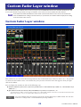
H [ST IN] button
Opens the STEREO IN window.
I [1-16] button
Opens the Custom Fader Layer (INPUT CH) CH 1–16 window.
J [17-32] button
Opens the Custom Fader Layer (INPUT CH) CH 17–32 window.
This is available only if you’re editing offline and have selected LS9-32 in the Model
Select field of the Mixer Setup screen, or if you’e editing online with the LS9-32 con-
nected.
K [ST IN] button
Opens the Custom Fader Layer (ST IN) window.

LS9 Editor Owner’s Manual
13
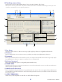
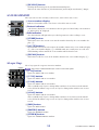
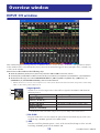
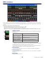
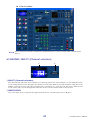
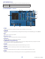
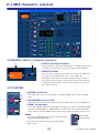
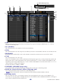
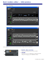
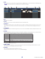
INPUT CH window
This window displays the mix parameters of INPUT CH 1–16, 17–32, 33–48
(*),
or 49–64
(*).
The parameters shown
in the window can be selected from the [View] menu or the menu that appears when you right-click (<control> key
+ click) in the window.
You can access this window in the following ways.
● From the [Windows] menu, choose [Overview] and select CH1-16/CH17-32/33-48
(*)
/49-64
(*)
●
Use the layer keys in the Master window to turn on the [1-16] button / [17-32] button / [33-48] button
(*)
/ [49-64] button
(*)
●
On the LS9 itself, assign one of the USER DEFINED KEYS to [CH1-16]/[CH17-32]/[CH33-48]
(*)
/[CH49-64]
(*)
in
[OVERVIEW] of [LS9 EDITOR CONTROL], and execute the function
(*)
INPUT CH 33-48, 49-64 can be viewed only if LS9-32 is selected in the Model Select field of the Mixer Setup window when editing
offline, or when editing online with the LS9-32.
A Input patch
Click here to select the input source that will be assigned to the INPUT CH, from the
following choices.
(*)
INPUT jacks 17-32 and slot 2 can be viewed only if you’re editing offline and have selected LS9-32 in
the Model Select field of the Mixer Setup screen, or if you’re editing online with the LS9-32.
B HA GAIN
Drag the knob in the screen to adjust the gain of the internal head amp or of the exter-
nal head amp (AD8HR) patched to the INPUT CH.
C 48V
Switches on/off the phantom power (+48V) of the internal head amp or of the external
head amp (AD8HR) patched to the INPUT CH.
NONE No assignment
IN 1–IN32
(*)
INPUT jacks 1–32
(*)
SLOT1-1...SLOT1-16,
SLOT2-1
(*)
...SLOT2-16
(*)
Input channels of an I/O card installed in a slot
2TR IN L, 2TR IN R L/R channels of the 2TR DIN jack
PB OUT L, PB OUT R L/R channels of USB memory recorder output
RACK1A, RACK1B...
RACK5L(A)...RACK8R(B)
L/R outputs of Rack 1–8
Overview window
1
2
3

LS9 Editor Owner’s Manual
14
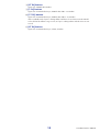
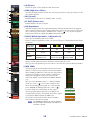
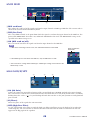
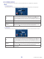
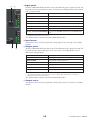
D Ø (Phase)
Inverts the phase of the signal after AD conversion.
E HPF (High Pass Filter)
Switches the high pass filter on/off. You can drag the numeric value up or down to edit
the cutoff frequency.
F INS (Insert)
Enables/disables the insert-in. (INPUT CH 1–32 only)
G D. OUT (Direct out)
Enables/disables the direct output.
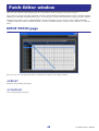
H EQ (Equalizer)
Switches the EQ on/off. The graph immediately below the button shows the approxi-
mate response of the EQ. You can drag within the graph to edit the response of the EQ.
To reset the EQ to flat response, hold down the <Ctrl>(< >) key of your computer
keyboard and click the graph (The HPF setting will remain).
I DYN1/DYN2 (Dynamics 1/Dynamics 2)
Turns the two dynamics processors on/off.
If Gate is assigned (Dynamics 1 only), the status of the gate is shown immediately below
the button.
If something other than Gate is assigned, a GR meter is shown immediately below the
button, and the amount of gain reduction is shown while this is on.
The type for each dynamics processor can be selected in the Selected Channel window.
J MIX SEND
The bar graphs located immediately below the button
show the send level of the signals sent from the INPUT
CH to VARI type MIX buses. You can also drag the bar
graph to left or right to set the send level. While you
drag the bar graph, the send level is shown in the
numerical display area for PAN/TO STEREO MONO
(
K).
You can set the minimum value (–∞ dB) by holding
down the <Ctrl>(< >) key of your computer key-
board and clicking the bar graph, or set the nominal
value (0.00 dB) by holding down the <Ctrl>(< >)
key and <Shift> key and clicking the bar graph.
The bar graph display will change according to the
send position (pre/post) and on/off status of the signal
sent from the INPUT CH to the MIX buses.
To switch a send on/off, click the channel number
located at the left of the bar graph.
For FIXED-type MIX buses, the bar graph is
fixed at nominal level (0 dB), and only the on/
off status is shown.
Gate status
indication
On/off status On On On Off
Open/closed
status
Closed Open Open —
Remarks
Gain reduction amount
is 30 dB or more
Gain reduction
amount is 0–30 dB
Gain reduction
amount is 0 dB
—
L
M
N
P
O
Q
K
J
4
6
7
8
5
9
• Pre/on (green)
• Pre/off (green)
• Post/on (yellow)
• Post/off (yellow)
NOTE

LS9 Editor Owner’s Manual
15
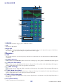
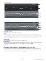
K PAN/TO STEREO MONO
The PAN knob adjusts the panning of the signal that is sent from the INPUT CH to the
STEREO bus L/R channels (or the L/C/R channels). You can set this to the center value
by holding down the <Ctrl>(< >) key of your computer keyboard and clicking this
knob.
The [ST] button is an on/off switch for the signal that is sent from the INPUT CH to
the STEREO bus.
The [M(C)] button is an on/off switch for the signal that is sent from the INPUT CH to
the MONO bus.
If LCR MODE is selected in the Selected Channel window, the [LCR] button will appear
instead of the [ST] button and [M(C)] button, and the [LCR] button will be an on/off
switch for the signal that is sent from the INPUT CH to the LCR bus.
L SEL (Select)
Selects the INPUT CH for which you want to perform operations. This is linked with
the INPUT section [SEL] keys on the LS9’s panel.
M CUE
This button cue-monitors the signal of the INPUT CH. This is linked with the INPUT
section [CUE] keys on the LS9’s panel.
N ON
Switches the INPUT CH on/off. This is linked with the INPUT section [ON] keys on
the LS9’s panel.
O Fader
Adjusts the input level of the INPUT CH. When the LS9 itself is in other than SENDS
ON FADER mode, this is linked with the INPUT section faders of the LS9’s panel.
The current fader value is shown in the numerical box located immediately below the
fader.
You can set this to the minimum value (–∞ dB) by holding down the <Ctrl>(< >) key
of your computer keyboard and clicking the fader knob, or set it to the nominal value
(0.00 dB) by holding down the <Ctrl>(< >) key and <Shift> key and clicking the
fader knob.
The numbers and alpha-
betical letters at the right
of the fader indicate the
mute groups to which
that channel belongs, and
show the Recall Safe and
Mute Safe status of the
channel.
P Channel number
This is the number of the INPUT CH. You can open the Selected Channel window for
this channel by double-clicking this number. If you hold down the <Ctrl>(< >) key
of your computer keyboard and double-click this, the Selected Channel window will
open as an additional view.
Q Channel name
This is a text box that displays the channel name. You can also edit the channel name in
this text box.
The background color will be the same as the background color of the icon in the chan-
nel select area of the Selected Channel window.
L
M
N
P
O
Q
K
The numbers of mute groups to which this
channel belongs are shown in red.
If this channel is set to Recall Safe, the R
character is shown in green.
If this channel is set to Mute Safe, the M char-
acter is shown in green.

LS9 Editor Owner’s Manual
16
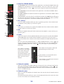
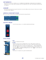
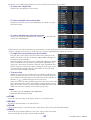
ST IN window
In this window you can view and edit the mix parameters of ST IN CH 1–4. The parameters shown in the window
can be selected from the [View] menu or the menu that appears when you right-click (<control> key + click) in the
window.
You can access this window in the following ways.
● From the [Windows] menu, choose [Overview] and then choose “ST IN”
● Use the layer keys in the Master window to turn on the [ST IN] button
● On the LS9 console, assign a USER DEFINED KEY to [LS9 EDITOR CONTROL]-[OVERVIEW]-[ST IN], and execute it
A INPUT PATCH
This selects the input source assigned to the ST IN CH. The input sources that can be
selected are the same as the INPUT CH.
B HA GAIN
Drag the knob in the screen to adjust the gain of the internal head amp or of the exter-
nal head amp (AD8HR) patched to the ST IN CH.
C 48V
Switches on/off the phantom power (+48V) of the internal head amp or of the external
head amp (AD8HR) patched to the ST IN CH.
D Ø (Phase)
Inverts the phase of the signal after AD conversion.
E HPF (High Pass Filter)
Switches the high pass filter on/off. You can drag the numeric value up or down to edit
the cutoff frequency.
F EQ (Equalizer)
Switches the EQ on/off (the L/R settings are linked). This is the same as the equalizer for
INPUT CH (➥ p.14).
6
1
2
5
3
4

LS9 Editor Owner’s Manual
17
G DYN1/DYN2 (Dynamics 1//Dynamics 2)
These buttons switch the two dynamics processors on/off. This is the same as the
dynamics 1/dynamics 2 for INPUT CH (➥ p.14).
H MIX SEND
This is the same as the mix send for INPUT CH (➥ p.14).
I BALANCE
The BALANCE knob adjusts the balance of the signal that is sent from the ST IN CH to
the STEREO bus L/R channels (or the L/C/R channels). Other than the BALANCE
knob, this is the same as PAN/TO STEREO MONO for an INPUT CH (➥ p.15).
J SEL (Select)
Selects the ST IN CH for which you want to perform operations. (L and R can be
selected separately.) This is linked with the ST IN section [SEL] keys on the LS9’s panel.
K CUE
This button cue-monitors the signal of the ST IN CH (L/R are linked). This is linked
with the ST IN section [CUE] keys on the LS9’s panel.
L ON
Switches the ST IN CH on/off (the L/R settings are linked). This is linked with the ST
IN section CH [ON] keys on the LS9’s panel.
M Fader
Adjusts the input level of the ST IN CH. When the LS9 itself is in other than SENDS ON
FADER mode, this is linked with the INPUT section faders of the LS9’s panel.
The current fader value is shown in the numerical box located immediately below the
fader. This is the same as the fader for INPUT CH (➥ p.15).
N Channel number
This is the number of the ST IN CH. You can double-click this number to open the
Selected Channel window for this channel. If you hold down the <Ctrl>(< >) key of
your computer keyboard and double-click this, the Selected Channel window will open
as an additional view.
O Channel name
This is a text box that displays the channel name. You can also edit the channel name in
this text box.
The background color will be the same as the background color of the icon in the chan-
nel select area of the Selected Channel window.
J
K
L
7
8
9
N
M
O

LS9 Editor Owner’s Manual
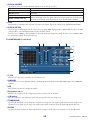
18
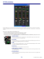
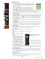
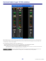
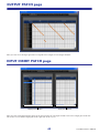
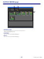
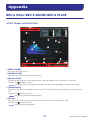
MIX window
In this window you can view and edit the parameters of MIX channels 1–16. The parameters shown in the window
can be selected from the [View] menu or the menu that appears when you right-click (<control> key + click) in the
window.
You can access this window in the following ways.
● From the [Windows] menu, choose [Overview] and then choose “MIX”
● Use the layer keys in the Master window to turn on the [MIX] button
● On the LS9 console, assign a USER DEFINED KEY to [LS9 EDITOR CONTROL]-[OVERVIEW]-[MIX], and execute it
A OUTPUT PATCH
Click here to select the output port that will be assigned to the MIX channel, from the
following choices.
(*) OMNI jacks 9–16 and SLOT2 can be viewed only if you’re editing offline and have selected LS9-32 in
the Model Select field of the Mixer Setup screen, or if you’re editing online with the LS9-32 connected.
If multiple patches have been made, only the first port is shown.
If you change the patching in this window, the port that had been assigned until then
will be cancelled, and only the newly selected port will be assigned.
B EQ (Equalizer)
Switches the EQ on/off. This is the same as the equalizer for INPUT CH (➥ p.14).
C DYN1(Dynamics 1)
Switches the dynamics processor on/off. This is the same as the dynamics 2 for INPUT
CH (➥ p.14).
D INS (Insert)
Enables/disables the insert-in.
OMNI1–OMNI16
(*)
OMNI jacks 1–16
(*)
SLOT1-1...SLOT1-16,
SLOT2-1
(*)
...SLOT2-16
(*)
Output channels of an I/O card installed in a slot
RACK1A, RACK1B...
RACK5L(A)...RACK8R(B)
L/R outputs of Rack 1–8
2TR OUT L, 2TR OUT R L/R channels of the 2TR OUT DIGITAL jack
REC IN L, REC IN R L/R channels of the USB memory recorder input
1
2
3
4

LS9 Editor Owner’s Manual
19
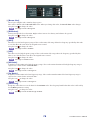
E MATRIX SEND
These bar graphs indicate the send levels of the signals sent from the
MIX channel to MATRIX 1–8 bus. You can also adjust the send lev-
els by dragging a bar graph to left or right. While you drag the bar
graph, the send level is shown in the numerical display area for
PAN/BALANCE (
6).
You can set the minimum value (–∞ dB) by holding down the
<Ctrl>(< >) key of your computer keyboard and clicking the bar
graph, or set the nominal value (0.00 dB) by holding down the
<Ctrl>(< >) key and <Shift> key and clicking the bar graph.
The bar graph display will change as follows according to the send position (pre/post)
and on/off status of the signal sent from the MIX channel to the MATRIX buses.
To switch a send on/off, click the channel number located at the left of the bar graph.
F PAN/BALANCE
The PAN knob adjusts the panning of the signal that is sent from the mix channel to the
STEREO bus L/R channels (or the L/C/R channels). You can set this to the center value
by holding down the <Ctrl>(< >) key of your computer keyboard and clicking this
knob. If assigned as a stereo bus, this adjusts the balance of the odd-numbered channel
and even-numbered channel. The stereo bus setting can be made in Mix Bus Setup of
the Mixer Setup screen.
The [ST] button is an on/off switch for the signal that is sent from the mix channel to
the STEREO bus.
The [MONO] button is an on/off switch for the signal that is sent from the mix channel
to the MONO bus.
If LCR MODE is selected in the Selected Channel window, the [LCR] button will
appear instead of the [ST] button and [MONO] button, and the [LCR] button will be
an on/off switch for the signal that is sent from the mix channel to the LCR bus.
G VARI/FIXED
Indicates the type (VARI or FIXED) of the currently selected MIX bus. This parameter
can be switched in Mix Bus Setup of the Mixer Setup screen.
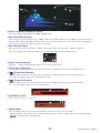
H SEL (Select)
Selects the MIX channel for which you want to make settings.
I CUE
This button cue-monitors the signal of the MIX channel.
J ON
Switches the MIX channel on/off.
K Fader
Adjusts the output level of the
MIX channel. The current fader
value is shown in the numeric box
immediately below the fader. You
can set this to the minimum value
(–∞ dB) by holding down the
<Ctrl>(< >) key of your com-
puter keyboard and clicking the
fader knob, or set it to the nominal
value (0.00 dB) by holding down
the <Ctrl>(< >) key and <Shift>
key and clicking the fader knob.
The numbers and alphabetical letters at the right of the fader indicate the mute groups to
which that channel belongs, and show the Recall Safe and Mute Safe status of the channel.
L Channel number
Indicates the number of the MIX channel. You can double-click this number to open
the Selected Channel window for this channel. If you hold down the <Ctrl>(< >) key
of your computer keyboard and double-click this, the Selected Channel window will
open as an additional view.
M Channel name
This is a text box that displays the channel name. You can also edit the channel name in
this text box.
The background color will be the same as the background color of the icon in the chan-
nel select area of the Selected Channel window.
6
5
8
9
J
L
M
7
K
• Pre/on (green))
• Pre/off (green)
• Post/on (yellow)
• Post/off (yellow)
The numbers of mute groups to
which this channel belongs are
shown in red.
If this channel is set to Recall Safe,
the R character is shown in green.
If this channel is set to Mute Safe,
the M character is shown in green.

LS9 Editor Owner’s Manual
20
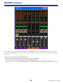
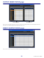
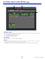
MATRIX window
In this window you can view and edit the parameters of MATRIX channels 1–8. The parameters shown in the win-
dow can be selected from the [View] menu or the menu that appears when you right-click (<control> key + click) in
the window.
You can access this window in the following ways.
● From the [Windows] menu, choose [Overview] and then choose “MATRIX”
● Use the layer keys in the Master window to turn on the [MTRX] button
● On the LS9 console, assign a USER DEFINED KEY to [LS9 EDITOR CONTROL]-[OVERVIEW]-[MATRIX], and execute
it
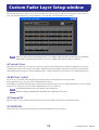
A página está carregando ...
A página está carregando ...
A página está carregando ...
A página está carregando ...
A página está carregando ...
A página está carregando ...
A página está carregando ...
A página está carregando ...
A página está carregando ...
A página está carregando ...
A página está carregando ...
A página está carregando ...
A página está carregando ...
A página está carregando ...
A página está carregando ...
A página está carregando ...
A página está carregando ...
A página está carregando ...
A página está carregando ...
A página está carregando ...
A página está carregando ...
A página está carregando ...
A página está carregando ...
A página está carregando ...
A página está carregando ...
A página está carregando ...
A página está carregando ...
A página está carregando ...
A página está carregando ...
A página está carregando ...
A página está carregando ...
A página está carregando ...
A página está carregando ...
A página está carregando ...
A página está carregando ...
A página está carregando ...
A página está carregando ...
A página está carregando ...
A página está carregando ...
A página está carregando ...
A página está carregando ...
A página está carregando ...
A página está carregando ...
A página está carregando ...
A página está carregando ...
A página está carregando ...
A página está carregando ...
A página está carregando ...
A página está carregando ...
A página está carregando ...
A página está carregando ...
A página está carregando ...
A página está carregando ...
A página está carregando ...
A página está carregando ...
A página está carregando ...
A página está carregando ...
A página está carregando ...
A página está carregando ...
A página está carregando ...
-
 1
1
-
 2
2
-
 3
3
-
 4
4
-
 5
5
-
 6
6
-
 7
7
-
 8
8
-
 9
9
-
 10
10
-
 11
11
-
 12
12
-
 13
13
-
 14
14
-
 15
15
-
 16
16
-
 17
17
-
 18
18
-
 19
19
-
 20
20
-
 21
21
-
 22
22
-
 23
23
-
 24
24
-
 25
25
-
 26
26
-
 27
27
-
 28
28
-
 29
29
-
 30
30
-
 31
31
-
 32
32
-
 33
33
-
 34
34
-
 35
35
-
 36
36
-
 37
37
-
 38
38
-
 39
39
-
 40
40
-
 41
41
-
 42
42
-
 43
43
-
 44
44
-
 45
45
-
 46
46
-
 47
47
-
 48
48
-
 49
49
-
 50
50
-
 51
51
-
 52
52
-
 53
53
-
 54
54
-
 55
55
-
 56
56
-
 57
57
-
 58
58
-
 59
59
-
 60
60
-
 61
61
-
 62
62
-
 63
63
-
 64
64
-
 65
65
-
 66
66
-
 67
67
-
 68
68
-
 69
69
-
 70
70
-
 71
71
-
 72
72
-
 73
73
-
 74
74
-
 75
75
-
 76
76
-
 77
77
-
 78
78
-
 79
79
-
 80
80


Yamaha LS9 Manual do usuário
- Categoria
- Equalizadores de áudio
- Tipo
- Manual do usuário
- Este manual também é adequado para
em outros idiomas
- español: Yamaha LS9 Manual de usuario
- français: Yamaha LS9 Manuel utilisateur
- italiano: Yamaha LS9 Manuale utente
- English: Yamaha LS9 User manual
- русский: Yamaha LS9 Руководство пользователя
- Nederlands: Yamaha LS9 Handleiding
- Deutsch: Yamaha LS9 Benutzerhandbuch
- dansk: Yamaha LS9 Brugermanual
- čeština: Yamaha LS9 Uživatelský manuál
- svenska: Yamaha LS9 Användarmanual
- polski: Yamaha LS9 Instrukcja obsługi
- Türkçe: Yamaha LS9 Kullanım kılavuzu
- suomi: Yamaha LS9 Ohjekirja
- română: Yamaha LS9 Manual de utilizare
Artigos relacionados
-
Yamaha Rev-X Manual do proprietário
-
Yamaha LS9 Manual do proprietário
-
-
Yamaha V5 Guia de usuario
-
-
Yamaha LS9 Editor Guia de instalação
-
Yamaha V3 Manual do proprietário
-
-
-