MO-EL GIROSOLE 769T - 769NS - 769N Manual do proprietário
- Tipo
- Manual do proprietário

MO-EL S.p.a.
Via Galvani, 18
42027 Montecchio Emilia (RE)
ITALY
tel +39 (0522) 868011
fax +39 (0522) 864223
www.mo-el.com - [email protected]
USO E MANUTENZIONE
USE AND MAINTENANCE
EMPLOI ET ENTRETIEN
GEBRAUCH UND WARTUNG
USO Y MANTENIMIENTO
USO E MANUTENÇAO
GIROSOLE
RISCALDATORE A RAGGI INFRAROSSI
CON LAMPADE ALOGENE AL QUARZO
HALOGEN QUARTZ INFRARED HEATER
GIROSOLE
Cod. 769
GIROSOLE A SOFFITTO
(Girosole suspended version)
Cod. 769S

2
1. ISTRUZIONI IMPORTANTI PER LA SICUREZZA
Leggere attentamente le istruzioni prima di installare il prodotto e
conservarle per future consultazioni. Il manuale deve essere conser-
vato e trasmesso al nuovo utente in caso di cessione dell’apparec-
chio.
1. L’ apparecchio è destinato esclusivamente all’impiego per il quale
è stato progettato, ovvero il raggiungimento ed il mantenimento
di un certo comfort termico per le persone tramite irraggiamento
su loro diretto. Il prodotto può anche essere usato per riscaldare
ambienti interni ma sono nella versione con sufsso ED ovvero
quella nella quale il prodotto viene abbinato al dispositivo di con-
trollo 9006ED. Il Costruttore non può essere considerato respon-
sabile per danni eventualmente provocati da un uso inadeguato.
2. Dopo aver disimballato il prodotto vericarne la completezza e
assicurarsi che non presenti segni di rotture, danneggiamenti o
manomissioni.
3. Tenere il materiale d’imballaggio lontano dai bambini, perché può
essere fonte di pericolo.
4. L’apparecchio può essere utilizzato da bambini di almeno 8 anni
(come pure da persone con ridotte capacità siche, sensoriali
o mentali, o prive di esperienza o della necessaria conoscenza)
purché essi siano sotto sorveglianza, oppure dopo che abbiano
ricevuto istruzioni relative all’uso sicuro e abbiano compreso i po-
tenziali pericoli. I bambini non devono giocare con l’apparecchio.
La pulizia e la manutenzione devono essere fatte dall’utilizzatore
e non da bambini privi di sorveglianza.
5. I bambini di età inferiore ai 3 anni dovrebbero essere tenuti a di-
stanza se non continuamente sorvegliati.
6. I bambini di età compresa tra i 3 e gli 8 anni devono solamente
accendere/spegnere l’apparecchio purché sia stato posto o in-
stallato nella sua normale posizione di funzionamento e che essi
ricevano sorveglianza o istruzioni riguardanti l’utilizzo dell’appa-
recchio in sicurezza e ne capiscano i pericoli.
7. I bambini di età compresa tra i 3 e gli 8 anni non devono inserire
la spina, regolare o pulire l’apparecchio né eseguire la manuten-
IT USO E MANUTENZIONE

3
zione a cura dell’utilizzatore.
8. Quando si utilizza il riscaldatore, è necessario seguire alcune re-
gole fondamentali (applicabili a tutti gli apparecchi elettrici):
•Non toccare l’apparecchio con le mani bagnate.
•Non maneggiare l’apparecchio con i piedi nudi.
•Non tirare mai il cavo di alimentazione per scollegare l’apparecchio
dalla presa di corrente; agire direttamente sulla spina.
9. L’apparecchio non deve essere installato in aree in cui possono
essere presenti gas inammabili o vapori pericolosi.
10. Evitare l’uso di prolunghe, perché può aversi pericolo di incendio.
11. Non apportare modiche che compromettano la sicurezza.
12. Mantenere le connessioni asciutte.
13. Se il cavo di alimentazione è danneggiato evitare di utilizzarlo, ma
farlo sostituire dal Costruttore o da un Servizio Assistenza Tecni-
ca autorizzato o comunque da una persona con qualica similare,
in modo da prevenire ogni rischio.
14. Scollegare l’apparecchio dall’alimentazione se non lo si utilizza
per lunghi periodi.
15. Il riscaldatore è fornito di una griglia di sicurezza che ha il compito
di proteggere le lampade dall’eventuale collisione con grossi cor-
pi estranei. Non rimuovere la griglia e non utilizzare l’apparecchio
se ne è sprovvisto.
ATTENZIONE — Alcune parti del presente prodotto possono
diventare molto calde e provocare ustioni. Bisogna prestare
particolare attenzione laddove sono presenti bambini e per-
sone vulnerabili.
2. INSTALLAZIONE ELETTRICA (MOD. 769 E 769S)
L’installazione dell’apparecchio deve essere effettuata da personale
competente e qualicato, in accordo con la norma CEI 64-8 che re-
gola gli impianti elettrici ed al regolamento UE 2015/1188. Prima di
effettuare il collegamento alla rete elettrica assicurarsi che l’impian-
to abbia un sistema di messa a terra efciente. Per il collegamento
utilizzare un cavo in gomma siliconica H07RN-F opportunamente di-
mensionato.
L’apparecchio è in classe I e ha grado di protezione IP65, che con-
sente generalmente anche l’installazione all’aperto. Per mantenere

4
questo grado di protezione alla polvere e all’acqua, il collegamento
all’alimentazione deve essere fatto con un sistema che sia almeno
IP65, secondo la normativa italiana CEI 64-8.
E’ necessario interporre a monte della linea di alimentazione un
dispositivo di sezionamento omnipolare di categoria di sovra-
tensione III, con distanza di apertura dei contatti di almeno 3 mm.
Assicurarsi che l’impianto sia protetto da un interruttore differ-
enziale magnetotermico con corrente d’intervento non superi-
ore a 30mA.
Assicurarsi che il cavo di alimentazione non possa andare in contatto
con i riflettori dell’apparecchio e che non entri nell’area di azione del
flusso luminoso.
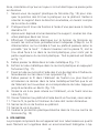
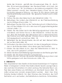
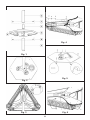
Sequenza delle operazioni
1. Svitare le 9 viti del coperchio che riporta l’etichetta dati targa (g. 4).
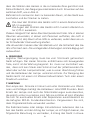
2. L’apparecchio è già predisposto per essere allacciato alla rete
elettrica sia con un collegamento monofase che con un collega-
mento trifase (3 fasi + neutro + terra):
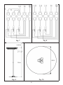
•Per realizzare un collegamento monofase, collegare i conduttori
di fase, neutro e terra rispettivamente nei poli della morsettiera
contrassegnati da L1- N - (g. 7). Utilizzare un cavo H07RN-F
3x2.5 mm2.
•Per realizzare un collegamento trifase, occorre eliminare i cavet-
ti A e collegare le 3 fasi, il neutro e la terra rispettivamente nei
poli della morsettiera contrassegnati da L3-L2-L1-N- (g. 8).
Utilizzare un cavo H07RN-F 5x1 mm2.
3. Il cavo di alimentazione può arrivare all’apparecchio in due modi:
•Dall’alto (mod. 769 e 769S) passando dall’apertura indicata e
dentro il passacavo di gomma (g. 4).
•Dal basso (mod. 769) nel modo seguente: svitare le 6 viti di bloc-
caggio della base, fare passare il cavo dentro la base di plastica,
far passare il cavo attraverso il palo no alla testata dell’apparec-
chio ed effettuare il cablaggio come sopra. Fissare le viti della
base avendo cura che il cavo di alimentazione venga bloccato
nell’apertura indicata (g. 5).

5
Tutti i riscaldatori ad irraggiamento sono volti a raggiungere e man-
tenere un certo confort termico alle persone che ne necessitano sia
all’esterno che in ambienti interni. E’ quindi molto importate studiare
con cura la zona in cui soggiornano le persone e di conseguenza
orientare l’irraggiamento verso di esse.
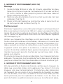
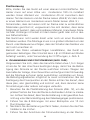
3. ASSEMBLAGGIO E POSIZIONAMENTO (MOD. 769)
Assemblaggio
1. Inlare il tavolino (E) nel tubo (A). Poi assemblare i due tubi (A) e
(G) per mezzo del giunto (C) e delle viti (B) e (F). Inne portare il
tavolino all’altezza della giunzione dei due pali e stringere i pomel-
li (D) (g. 1).
2. Inlare il tubo nella base e serrare la vite no a quando il tubo
rimane saldamente ssato (g. 2).
3. Inlare la testata dell’apparecchio sulla sommità del tubo e serra-
re le 3 viti no a quando il tubo rimane saldamente ssato (g. 3).
Posizionamento
Posizionare l’apparecchio su supercie piana e regolare. le lampade
devono trovarsi ad una altezza minima di 180 cm. Lasciare una distan-
za libera minima di 40 cm tra la parte più alta del riscaldatore e il softto
(g. 9). Lasciare libera l’area antistante per una distanza minima di
almeno un metro (g. 9).
Assicurarsi che il riscaldatore non sia orientato verso il softto o ver-
so materiali inammabili e che non ci sia la possibilità che materiale
inammabile, tende o materiali combustibili vengano a contatto col
riscaldatore o si trovino nelle sue vicinanze.
L’apparecchio non deve essere posizionato immediatamente sotto
una presa di corrente, nè di fronte ad essa. Installarlo in modo da im-
pedire che gli interruttori o i comandi vengano toccati da chi si trova
nella vasca da bagno o nella doccia.
Se c’è il rischio di cadute accidentali, ssare l’apparecchio in modo
opportuno. Ad esempio, si può ancorare la base al pavimento con
tasselli mediante i tre appositi fori come in g. 5.

6
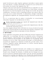
4. ASSEMBLAGGIO E POSIZIONAMENTO (MOD. 769S)
Assicurarsi che il cavo da utilizzare abbia una lunghezza di circa 1.5
m maggiore rispetto a quella utile per il collegamento, per consentire
le operazioni di ssaggio del Girosole. A causa dell’ingombro dell’ap-
parecchio, del suo peso e della necessità di lavorare appoggiandsi su
una scala, è consigliabile che le operazioni di ssaggio vengano ese-
guite da due persone. Nello stabilire il punto di ssaggio sul softto,
fare attenzione che la supercie sia piana, regolare, solida e che non
passino sotto di essa condutture elettriche o tubature.
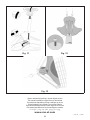
1. Utilizzare il supporto di plastica del Girosole (g. 12) per stabilire
la posizione dei 6 fori da praticare sul softto. Fare attenzione
ad orientare il supporto nella direzione voluta, in considerazione
dell’uscita del cavo.
2. Fare i 6 fori di ssaggio utilizzando un trapano con punta di dia-
metro 10.
3. Dopo aver riposto momentaneamente il supporto, inlare nei fori
i tasselli di plastica.
4. Eseguire l’installazione elettrica sulla morsettiera del Girosole se-
condo le istruzioni riportate precedentemente (Cap.2). Il cavo di
alimentazione nel modello a softto passerà secondo la modalità
“dall’alto”. Dovrà attraversare sia il passacavo, sia il foro posto
di fronte ad esso nel raccordo di plastica, per uscire inne dalla
parte superiore del raccordo in plastica. L’intero percorso è mo-
strato in g. 11
5. Far passare il cavo attraverso il tubo metallico (g. 11)
6. Inlare il tubo metallico nel raccordo di palstica, premendo con
forza (g. 11).
7. Fissare il tubo al raccordo con utilizzando le 2 viti di diametro
3.5x6 autolettanti sui due fori contrapposti (g. 11).
8. Far passare il cavo dentro l’elemento di ssaggio (visto preceden-
temente) ed inlare questultimo nel tubo metallico. Fare attenzio-
ne che la vite dell’elemento si trovi in corrispondenza del tubo.
Premere no a che si sente uno scatto (g. 12).
9. Avvitare la vite a brugola che si trova sull’elemento, ssandolo in
questo modo al tubo (g. 12).
10. Avvitare l’elemento al softto utilizzando le 6 viti in dotazione,
senza stringere.

7
11. Tirare il cavo, in modo che la parte dentro al tubo resti distesa.
12. Stringere le 6 viti di ssaggio al softto.
13. Stringere la vite a brugola.
14. Inserire il coperchietto di plastica bianca nel foro al centro del
Girosole (g. 13)
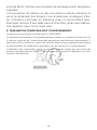
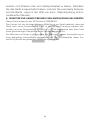
5. UTILIZZO
L’elemento principale dell’apparecchio è la lampada lineare di quarzo
con lamento in tungsteno in ambiente alogeno. L’apparecchio la-
vora a piena potenza già qualche secondo dopo l’accensione. L’area
riscaldata ha un diametro di 4-6 metri intorno all’apparecchio (g. 10).
Ogni lampada può essere accesa singolarmente agendo sul proprio
interruttore (g. 6). Prima di premere l’interruttore, afferrare salda-
mente l’impugnatura evitando di toccare le parti metalliche.
Assicurarsi che il riscaldatore rivolga i suoi raggi nella zona che si vuo-
le riscaldare. Se necessario, cambiare l’angolo di inclinazione agendo
sull’impugnatura, come mostrato in g. 6.
Se non c’è nessuno nel locale da riscaldare, si raccomanda di spe-
gnere l’apparecchio e di staccare la spina.
Evitare di esporre la cute ai raggi dell’apparecchio per distanze
inferiori a 50 cm.
Evitare di esporre gli occhi ai raggi dell’apparecchio per distanze
inferiori a 2,70 m.
Non utilizzare in stanze piccole occupate da persone incapaci di uscire da
sole solo se esse non sono poste sotto costante sorveglianza a meno che
non si tratti del prodotto con suffisso ED. In questo caso l’apparecchio di
riscaldamento è dotato di un dispositivo esterno i controllo della tempera-
tura ambientale.
Tutti gli utilizzatori devono essere informati riguardo tutti gli aspetti
del funzionamento e della sicurezza relativi all’apparecchio. Queste
istruzioni devono essere conservate come riferimento.

8
6. PULIZIA
Qualsiasi operazione di manutenzione deve essere effettuata ad ap-
parecchio scollegato dalla rete elettrica. Il riscaldatore Girosole non
contiene parti in movimento, quindi la manutenzione è limitata. Oc-
corre solo vericare che non vi sia polvere o sporcizia sulle parabo-
le riettenti o sulle lampade, poichè potrebbero provocare dei surri-
scaldamenti che ridurrebbero la vita delle lampade stesse. Per pulire
l’apparecchio, stronarlo leggermente con un panno inumidito con
acqua o con uno spolverino.
7. MANUTENZIONE
Le lampade del Girosole sono robuste, e, se si evitano vibrazioni e
colpi, la loro durata è di circa 5000 ore. Assieme alle lampade devono
essere cambiati anche i supporti in silicone, che comunque devono
essere sostituiti ancor prima se presentano segni di invecchiamento.
Per le sostituzioni o le eventuali riparazioni, rivolgersi esclusivamen-
te a Centri di Assistenza Tecnica autorizzati Mo-El. Assicurarsi che i
ricambi siano originali.
L’accumulo di calcare o incrostazioni saline riducono la vita e il rendi-
mento delle lampade; si consiglia pertanto di evitare l’utilizzo prolun-
gato in presenza di acqua o nebbia salina. Eventuali residui di acqua
salata dovranno essere rimossi prima dell’uso, ad apparecchio scolle-
gato, con risciacqui di acqua dolce.
8. SMALTIMENTO AMBIENTALMENTE COMPATIBILE
Questo prodotto è conforme alla Direttiva EU 2002/96/EC.
Il simbolo del cestino barrato riportato sull’apparecchio indica che il prodotto, alla ne della propria vita
utile, dovendo essere trattato separatamente dai riuti domestici, deve essere conferito in un centro di
raccolta differenziata per apparecchiature elettriche ed elettroniche oppure riconsegnato al rivenditore
al momento dell’acquisto di una nuova apparecchiatura equivalente.
L’utente è responsabile del conferimento dell’apparecchio a ne vita alle appropriate strutture di raccol-
ta, pena le sanzioni previste dalla vigente legislazione sui riuti.
L’adeguata raccolta differenziata per l’avvio successivo dell’apparecchio dismesso al riciclaggio, al trat-
tamento e allo smaltimento ambientalmente compatibile contribuisce ad evitare possibili effetti negativi
sull’ambiente e sulla salute e favorisce il riciclo dei materiali di cui è composto il prodotto.
Per informazioni più dettagliate inerenti i sistemi di raccolta disponibili, rivolgersi al servizio locale di
smaltimento riuti o al negozio in cui è stato effettuato l’acquisto.
I produttori e gli importatori ottemperano alla loro responsabilità per il riciclaggio, il trattamento, lo
smaltimento ambientalmente compatibile sia direttamente sia partecipando ad un sistema collettivo.

9
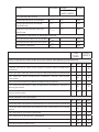
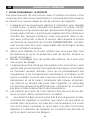
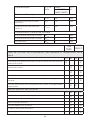
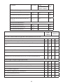
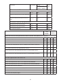
Dato Simbolo Valore Unità
769-769S
769ED-769SED
Potenza termica
Potenza termica nominale Pnom 3.6 kW
Potenza termica minima
(indicativa)
Pmin 1.2 kW
Massima potenza termica
continua
Pmax c 3.6 kW
Consumo ausiliario di energia elettrica
Alla potenza termica normale elmax 0 kW
Alla potenza termica minima elmin 0 kW
In modo StandBy elSB 0 kW
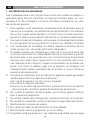
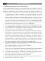
769
769S
769ED
769SED
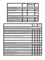
Tipo di potenza termica/controllo della temperatura ambiente
SI NO SI NO
Potenza termica a fase unica senza controllo della temperatura
ambiente X X
Due o più fasi manuali senza controllo della temperatura ambiente X X
Con controllo della temperatura ambiente tramite termostato
meccanico X X
Con controllo elettronico della temperatura ambiente X X
Con controllo elettronico della temperatura ambiente e temporiz-
zatore giornaliero X X
Con controllo elettronico della temperatura ambiente e temporiz-
zatore settimanale X X
Altre opzioni di controllo
SI NO SI NO
Controllo della temperatura ambiente con rilevamento di presenza X X
Controllo della temperatura ambiente con rilevamento di nestre
aperte X X
Con opzione di controllo a distanza X X
Con controllo di avviamento adattabile X X
Con limitazione del tempo di funzionamento X X
Con termometro globo nero X X

10
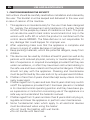
1. CAUTION REGARDING THE SECURITY
Instructions should be carefully read before installation and retained by
the user. The booklet must be keeped and delivered to the new user
in case of cession of the machine.
1. This appliance is intended solely for the use it has been designed
for, namely the achievement and maintance of a ertain thermal
comfort for the people by means of irradiation on them. The prod-
uct can also be used to heat indoor environments but only in the
version with sufx ED in which the product is combinet with the
control device 9005ED. The Manufacturer is not responsible for
any damage that could happen for improper use.
2. After unpacking make sure that the appliance is complete and
shows no signs of visible damage or tampering.
3. Keep packing materials, which are potential dangers, away from
children.
4. The device can be used by children at least 8 years (as well as by
persons with reduced physical, sensory or mental capabilities, or
lack of experience or required knowledge) provided that they are
under surveillance, or after they have been instructed relating to
the safe use and have understood the potential dangers. Children
should not play with the appliance. Cleaning and maintenance
must be performed by the user and not by unsupervised children.
5. Children of less than 3 years should be kept away unless continu-
ously supervised.
6. Children aged from 3 years and less than 8 years shall only switch
on/off the appliance provided that it has been placed or installed
in its intended normal operating position and they have been giv-
en supervision or instruction concerning use of the appliance in a
safe way and understand the hazards involved.
7. Children aged from 3 years and less than 8 years shall not plug in,
regulate and clean the appliance or perform user maintenance.
8. Some fundamental rules which apply to all electrical devices
must be observed when using the heater:
•Do not touch the heather with wet hands.
•Do not handle with bare feet.
EN USE AND MAINTENANCE

11
•Do not pull the electric cord or the device itself to unplug it from
the socket; pull the plug directly.
9. Heaters should not be installed in areas where hazardous vapours
may be present.
10. Avoid the use of an extension cord with this product, because
the extension cord may overheat and cause a risk of re.
11. Do not apply any modication to the product that could compro-
mise the safety.
12. Keep connections dry.
13. If the power supply cord is damaged, avoid to use the appliance.
For power cord replacing, please contact the manufacturer or the
technical service or a person with similar qualication, in order to
avoid any risk.
14. If the appliance is not used for a long period, disconnect it from
the power supply.
15. The heaters are tted with safety guards. These are intended
only to stop large objects from hitting the emitters. On no ac-
count should the heater be operated with the guard removed.
CAUTION — Some parts of this product can become very hot
and cause burns. Particular attention has to be given where
children and vulnerable people are present.
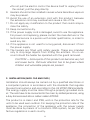
2. INSTALLATION (MOD. 769 AND 769S)
Installation should always be carried out by a qualied electrician or
a competent person in accordance with the standards that regulate
the electrical systems and according to the UE 2015/1188 standards.
The energy supply must be done through a properly grounded sock-
et. The sets have to be connected to the main by skilled personnel, using
a duly dimensioned silicon rubber cable H07RN-F.
The product is in class I and IP65, wich is the protection rate for the
units to be used even outdoor. For keeping the protection rate of the
appliance, the connection of the appliance with the power supply
must be done by means of a minimum IP65 system, as per the ef-
fective regulations in each country.

12
An overvoltage category III Combined Circuit breaker and Re-
sidual Current Device (RCD) with rated earth leakage operation
not exceeding 30mA must be fitted upstream on the supply
line. The circuit breaker must have a contact opening distance of at
least 3 mm.
Ensure that the supply cable is well mounted and that it does not
come into contact with the reflector of the heater or that it does not
trail into the heated area.
Sequence
1. Unscrew the 9 screws of the cover that have the data label (g. 4).
2. The set is already arranged to be connected to the main both by
single phase and three phase connection (3 phase + neutral +
ground):
•To carry out a single phase connection, connect the phase leads,
neutral and ground to the poles of the terminal as respectively
marked L1-N- (g. 7). Use a cable H07RN-F 3x2.5 mm2.
•To carry out a three phase connection, eliminate the wires A and
connect the 3 phases, neutral and ground to the poles of the
terminal as respectively marked L3-L2-L1-N- (g. 8). Use a
cable H07RN-F 5x1 mm2.
3. The power cord can reach the appliance in two ways:
•From the top (mod. 769 and 769S) and through the opening and
the rubber cable-carrier (see g. 4).
•From the bottom (mod. 769) in the following way: unscrew the
6 screws of the base, pass the power cord through the plastic
base and through the pole until the head of the appliance and
connect the power cord as above. Tight the screw of the base
being careful that the pwer cord is locked into the opening like
in g. 5.
All irradiation heaters are designed to achieve and maintain a certain
thermal comfort to the people who need it both outside and inside. It
is therefore very important to carefully study the area where people
stay and consequently direct the radiation towards them.

13
3. ASSEMBLY AND FIXING (MODEL 769)
Assembling
1. Insert the table (E) into the pipe (A). Then assemble the two pipes
(A) and (G) by means of the coupling (C) and the screws (B) and
(F). Finally, bring the table up to the junction of the two pipes and
tighten the knobs (D) (g. 1).
2. Insert the assembled pipes into the base and tight the screw until
the pipes are xed into one pole (g. 2).
3. Insert the head of the appliance at the top of the pole and tight
the 3 screws until the pole is xed (g. 3).
Placement
Place the appliance upon a plain and regular surface. The lamps
should be mounted at a minimum of 180 cm above ground level. A
minimum air gap of 40 cm should always be allowed between the
top of the heater and a ceiling or roof (g. 9). A safety distance of not
less than 100 cm should always be left in front of the appliance or
too near.
Be sure that the heater is not facing the ceiling or inammable sub-
stances; ensure that there is no possibility of inammable material,
combustible material or curtains coming into contact with the heater,
or lie near the heater.
The appliance must not be located neither directly below, nor in
front of a socket-outlet. It must be installed so as to prevent that the
switches can be touched from those who are in the shower.
If there is the risk of accidental falling down of the appliance, x it to
the in a proper way. For example, the base could be fastened to the
ground with dowels by means of the 3 holes in the base (g. 5).
4. ASSEMBLY AND FIXING (MODEL 769S)
Ensure that the cable to be used is about 1.5 m longer than required
for connection, so as to enable the xing operations of the Girosole
to be carried out. Because of the size and weight of the equipment
and of the need to work standing on a ladder, it is advisable that x-
ing operations be carried out by two persons. When determining the

14
xing point on the ceiling, ensure that the surface is at, level and
solid, and that no electric cables or pipes run beneath it.
1. Use the plastic housing of the Girosole (g. 12) to determine the
position of the 6 holes in the ceiling. Take care to position the
housing in the desired direction, relative to the exit point of the
cable.
2. Make the 6 xing holes using a no. 10 diameter drill.
3. Temporarily set aside the housing and push the plastic rawlplugs
into the holes.
4. Carry out electrical installation on the terminal panel of the Giro-
sole according to previous instructions (Ch.2). The power cable
of the ceiling mounted model passes “from above”. It must pass
through the cable carrier and also the hole in front of it in the
plastic connector, so as to exit from the upper part of the plastic
connector. The complete process is shown in g. 11.
5. Insert the cable through the metal tube (g. 11).
6. Firmly push the metal tube into the plastic connector (g. 11).
7. Fix the tube to the connector by screwing the two 3.5 x 6 self-
tapping screws into the two opposing holes (g. 11).
8. Insert the cable into the xing unit (as shown previously) and
insert this into the metal tube. Ensure that the screw on the unit
is aligned with the tube. Press until a click is heard (g. 12).
9. Use the Allen screw on the unit to x it to the tube (g. 12).
10. Fit the unit to the ceiling by means of the 6 screws supplied,
without tightening.
11. Pull the cable so as to straighten it inside the tube.
12. Tighten the 6 xing screws into the ceiling.
13. Tighten the Allen screw.
14. Insert the white plastic cover into the hole in the centre of the
Girosole (g. 13).
5. USE
The essential element of the heater is the halogen lled quartz linear
lamp with a tungsten element. The heater operates at full output
almost immediately. The heating reaches a distance of about 4-6 me-
ters around the appliance (g. 10).
Every lamp can be switched on with its switch (g. 6). Before press-
ing the switch, seize rmly the grip and avoid to touch the metal

15
parts. Ensure that the heater is aiming its warmth into the target area
by adjusting heater angles as necessary by using the adjustment de-
vice on the bracket (g. 6).
In unoccupied premises it is recommended that the heating system
is switched off and isolated from the electrical supply.
Avoid exposing skin to the rays of the appliance for distances
less than 50 cm.
Avoid exposing eyes to the rays of the appliance for distances
less than 2.70 m.
Do not use it in small rooms used by people who are unable to leave
such rooms on their own unless they are under constant surveillance
or unless the product is in the version with the suffix ED. In this case
the heating appliance does feature an external device to control am-
bient temperature.
All users should be made aware of all aspects of operation and safety
and these instructions should be retained for reference.
6. CLEANNESS
Every mainteinance operation should be done when the appliance
is disconnected from the power supply. Mo-El Girosole heaters con-
tain no moving parts and therefore very little maintenance is required
other than to ensure that there is no excessive build-up of dust/dirt
on the reectors or emitters as this can cause overheating and pre-
mature emitter failure. To clean the appliance, wipe off with a damp
cloth.
7. MAINTENANCE
The lamps used in the Girosole are robust and if knocks and shock
vibrations are avoided, they will last for around 5000 hours. When
changing the lamps, also the silicon bumpers connected with each
lamp must be substituted. They should be substituted even before
if there are signs of aging. Due to the special sealing and anti-shock
design of the heater, the emitters are not intended to be user re-
placeable. Please ensure that all emitters are replaced via the Mo-El
service network.
The accumulation of limestone or incrustations reduces the life and

16
the efciency of the lamps; it is suggested therefore to avoid the
continued use in presence of water or salt fog. Eventual leavings of
salt water will have to be removed before the use, after having dis-
connected the appliance, by means of soak in sweet water.
8. ENVIRONMENTALLY COMPATIBLE DISPOSAL OF THE APPLIANCE
This product conforms to EU Directive 2002/96/EC.
This appliance bears the symbol of the barred waste bin. This indicates that, at the end of its
useful life, it must not be disposed of as domestic waste, but must be taken to a collection
centre for waste electrical and electronic equipment, or returned to a retailer on purchase
of a replacement.
It is the user’s responsibility to dispose of this appliance through the appropriate channels
at the end of its useful life. Failure to do so may incur the penalties established by laws
governing waste disposal.
Proper differential collection, and the subsequent recycling, processing and environmentally
compatible disposal of waste equipment avoids unnecessary damage to the environment
and possible related health risks, and also promotes recycling of the materials used in the
appliance.
For further information on waste collection and disposal, contact your local waste disposal
service, or the shop from which you purchased the appliance.
Manufacturers and importers full their responsibilities for recycling, processing and en-
vironmentally compatible disposal either directly or by participating in collective systems.

17
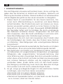
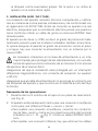
769
769S
769ED
769SED
Type of heat output/room temperature control
YES NO YES NO
Single stage heat output, no room temperature control X X
Two or more manual stages, no room temperature control X X
With mechanic thermostat room temperature control X X
With electronic room temperature control X X
With electronic room temperature control plus day timer X X
With electronic room temperature control plus week timer X X
Other control options
YES NO YES NO
Room temperature control, with presence detection X X
Room temperature control, with open window detection X X
With distance control option X X
With adaptive start control X X
With working time limitation X X
With black bulb sensor X X
Data Symbol Value Unit
769-769S
769ED-769SED
Thermal power
Nominal thermal power Pnom 3.6 kW
Minimum thermal
power(indicative)
Pmin 1.2 kW
Maximum continuous ther-
mal power
Pmax c 3.6 kW
Auxiliary consumption of electricity
At normal thermal power elmax 0 kW
At minimum thermal power elmin 0 kW
StandBy mode elSB 0 kW

18
1. NOTES CONCERNANT LA SÉCURITÉ
Lire attentivement les instructions avant d’installer le produit et les
conserver pour de futures consultations. Le manuel doit etre conserve
et transmis au nouvel usager en cas de cession de l’appareil.
1. L’appareil est exclusivement destiné à l’utilisation pour laquelle
il a été conçu, à savoir atteindre et maintenir un certain confort
thermique pour les personnes par rayonnement dirigé sur les per-
sonnes elles-mêmes. Le produit peut également être utilisé pour
chauffer des espaces intérieurs, mais uniquement dans la ver-
sion avec sufxe ED, à savoir la version dans laquelle le produit
est associé au dispositif de contrôle 9006ED/9005ED. Le Fabri-
cant ne peut être tenu pour responsable des dommages causés
par une utilisation impropre.
2. Après avoir déballer le produit vériez que vous avez bien tous
les éléments et qu’ils ne présentent pas de rayures, bosses ou
autres dommages.
3. Gardez l’emballage hors de portée des enfants, car il peut être
une source de danger.
4. L’appareil peut être utilisé par des enfants d’au moins 8 ans, ainsi
que par des personnes dont les capacités physiques, sensorielles
ou mentales seraient réduites, voire qui ne posséderaient pas
l’expérience ni les connaissances nécessaires, à condition qu’ils
soient surveillés ou qu’ils aient reçu les instructions d’utilisation
nécessaires et qu’ils soient conscients des risques potentiels.
Les enfants ne doivent pas jouer avec l’appareil. Le nettoyage
et l’entretien doivent être effectués par l’utilisateur et ne doivent
pas être conés à des enfants sans surveillance.
5. Les enfants de moins de 3 ans doivent être tenus à bonne dis-
tance à moins d’être constamment surveillés.
6. Les enfants d’âge compris entre 3 et 8 ans ne peuvent qu’allu-
mer/éteindre l’appareil à condition que celui-ci ait été placé ou
installé dans sa position normale de fonctionnement et à condi-
tion qu’ils soient surveillés ou qu’ils aient reçu des instructions
relatives à l’utilisation de l’appareil en conditions de sécurité et
qu’ils en aient compris les dangers.
FR UTILISATION ET ENTRETIEN

19
7. Les enfants d’âge compris entre 3 et 8 ans ne doivent en aucun
cas brancher la che d’alimentation, régler l’appareil, le nettoyer
ni en effectuer l’entretien qui incombe à l’utilisateur.
8. Les règles fondamentales applicables à tous les appareils élec-
triques sont à suivre quand vous utilisez votre parasol chauffant:
•Ne pas toucher l’appareil avec les mains mouillées.
•Ne pas déplacer l’appareil avec les pieds nus.
•Ne jamais tirer le câble d’alimentation pour débrancher l’appareil
; agir directement sur la che.
9. L’appareil ne doit pas être installé dans des locaux où sont sus-
ceptibles d’ être présents des gaz inammables ou des vapeurs
représentant un risque.
10. Eviter l’utilisation de rallonges, il pourrait y avoir un incendie.
11. Maintenir les connexions sèches.
12. Ne pas apporter de modications au produit.
13. Si le cable d’alimentation est endommagé, éviter de l’utiliser,
Fait lui substituer du constructeur ou de son service d’assistence
technique ou de toute façon d’une personne avec une qualica-
tion similaire, pour prévenir chaque risque.
14. Débrancher l’appareil lorsqu’il n’est pas utilisé.
15. L’appareil est équipé d’une grille de sécurité qui sert à protéger
les tubes des chocs en tout genre. Ne pas la retirer et ne jamais
utiliser l’appareil si cette grille venait à manquer.
2. INSTALLATION (MOD. 769 ET 769S)
L’installation de l’appareil doit être effectuée par un personnel quali-
é et compétent, conformément à la norme relative aux installations
électriques et conformément au règlement UE 2015/1188. Avant de
brancher votre appareil, au réseau électrique, assurez-vous que votre
installation électrique comporte bien un système de mise à la terre.
Pour le réseau utiliser un câble en caoutchouc siliconé (H07 RN-F)
dimensionné en mode appropriée.
Le produit appartient à la classe I et IP65, qui correspond au niveau
de protection généralement prévu pour des appareils susceptibles
d’être installés en plein air. Si vous voulez maintenir le niveau de pro-
tection de l’appareil contre la poussière et l’eau, le branchement de
celui-ci doit se faire au minimum avec un système IP65.

20
Un disjoncteur de surtension de catégorie III et un dispositif
de courant résiduel(RCD) avec protection contre les courants
de fuite à la terre ne dépassant pas 30mA doit être installé en
amont du circuit électrique. Le disjoncteur doit avoir une distance
d’ouverture des contacts d’au moins 3 mm.
S’assurer que le câble d’alimentation ne puisse entrer en contact avec
les réflecteurs de l’appareil et qu’il ne se trouve pas dans le rayon d’ac-
tion du flux lumineux.
Séquence des opérations
1. Dévisser les 9 vis du couvercle portant la plaquette d’indication
des données (g. 4).
2. L’appareil est déjà prévu pour être relié au réseau électrique soit
avec un branchement monophasée, soit avec un branchement
triphasée (3 phases + neutre + terre).
•Pour réaliser un branchement monophasée, relier les conduc-
teurs de phase, neutre et terre respectivement dans les poles
du bornier marqué par L1- N - (g. 7). Usez un cable H07RN-
F 3x2.5 mm2.
•Pour réaliser un branchement triphasée, il faut éliminer les
câbles A et relier les 3 phases, le neutre et la terre respective-
ment dans les poles du bornier marqué par L3-L2-L1-N- (g.
8). Usez un cable H07RN-F 5x1 mm2.
3. Le câble d’alimentation peut arriver à l’appareil de deux manières:
•Par le haut (mod. 769 et 769S) en passant par l’ouverture et par le
passe l de caoutchouc (g. 4).
•Par le bas (mod. 769) de la façon suivante: dévisser les 6 vis
bloquant la base, faire coulisser le câble à l’intérieur de la base
en plastique, puis à travers le pied jusqu’à la tête de l’appareil et
effectuer le câblage comme indiqué ci-dessus. Fixer les vis de
la base en faisant attention à ce que le câble d’alimentation ne
reste pas coincé dans l’embrasure indiquée sur la g. 5.
Tous les radiateurs à rayonnement sont conçus pour atteindre et
maintenir un certain confort thermique pour les personnes, aussi
bien en intérieur qu’en extérieur. Aussi, il est très important de bien
tenir compte de la zone où les personnes séjournent et d’orienter le
rayonnement en conséquence.
A página está carregando...
A página está carregando...
A página está carregando...
A página está carregando...
A página está carregando...
A página está carregando...
A página está carregando...
A página está carregando...
A página está carregando...
A página está carregando...
A página está carregando...
A página está carregando...
A página está carregando...
A página está carregando...
A página está carregando...
A página está carregando...
A página está carregando...
A página está carregando...
A página está carregando...
A página está carregando...
A página está carregando...
A página está carregando...
A página está carregando...
A página está carregando...
A página está carregando...
A página está carregando...
A página está carregando...
A página está carregando...
A página está carregando...
A página está carregando...
A página está carregando...
A página está carregando...
-
 1
1
-
 2
2
-
 3
3
-
 4
4
-
 5
5
-
 6
6
-
 7
7
-
 8
8
-
 9
9
-
 10
10
-
 11
11
-
 12
12
-
 13
13
-
 14
14
-
 15
15
-
 16
16
-
 17
17
-
 18
18
-
 19
19
-
 20
20
-
 21
21
-
 22
22
-
 23
23
-
 24
24
-
 25
25
-
 26
26
-
 27
27
-
 28
28
-
 29
29
-
 30
30
-
 31
31
-
 32
32
-
 33
33
-
 34
34
-
 35
35
-
 36
36
-
 37
37
-
 38
38
-
 39
39
-
 40
40
-
 41
41
-
 42
42
-
 43
43
-
 44
44
-
 45
45
-
 46
46
-
 47
47
-
 48
48
-
 49
49
-
 50
50
-
 51
51
-
 52
52


MO-EL GIROSOLE 769T - 769NS - 769N Manual do proprietário
- Tipo
- Manual do proprietário
em outras línguas
- español: MO-EL GIROSOLE 769T - 769NS - 769N El manual del propietario
- français: MO-EL GIROSOLE 769T - 769NS - 769N Le manuel du propriétaire
- italiano: MO-EL GIROSOLE 769T - 769NS - 769N Manuale del proprietario
- English: MO-EL GIROSOLE 769T - 769NS - 769N Owner's manual
- Deutsch: MO-EL GIROSOLE 769T - 769NS - 769N Bedienungsanleitung
Artigos relacionados
-
 MO-EL HATHOR 79104 - 79204 - 79304 - 791N - 79204N - 79304N - 791LGW - 792LGW - 793LGW Manual do proprietário
-
 MO-EL IRIS 866NP - 866N - 866NRC - 867NP - 867N - 867NRC Manual do proprietário
-
 MO-EL FIORE 766N - 767N Manual do proprietário
-
 MO-EL PETALO 722CP - 722CRC - 728CP - 728CRC Manual do proprietário
-
 MO-EL AAREN INCASSO 9011 Manual do proprietário
-
 MO-EL TRIPODE 2473 Manual do proprietário
-
 MO-EL PALO ELEGANCE 4464 Manual do proprietário
-
 MO-EL HOT-TOP 9824SD Manual do proprietário


Outros documentos
-
Emmeti X-REVO XX19W-21 Manual do proprietário
-
Master COFFEE 12-18 005229 E16R2 Manual do proprietário
-
-
Vonroc PH513AC Manual do usuário
-
-
S&P HED-1800 Installation Manual And Operating Instructions
-
 Olimpia Splendid Unico Twin S1 Manual do usuário
-
HTW CONJUNTO SUELO TECHO TWIN ADMIRA Manual do usuário
