
701 S. RIDGE AVENUE
TROY, OHIO 45373
937 332-3000
www.hobartcorp.com
4732 & 4732A CHOPPERS
MODEL
4732 ML-18887 (PAINTED, NON-REMOVABLE PAN)
ML-19282 (SST, NON-REMOVABLE PAN)
ML-19809 (SST, NON-REMOVABLE PAN)
4732A ML-19689 (PAINTED, REMOVABLE PAN)
ML-19690 (SST, REMOVABLE PAN)
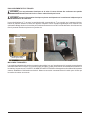
MODEL 4732 CHOPPER
FORM 34747 Rev. C (April 2023)

– 2 –
Installation, Operation and Care of
4732 & 4732A Choppers
SAVE THESE INSTRUCTIONS
GENERAL
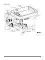
The 4732 and 4732A Choppers are equipped with a 3 HP motor that rotates the worm at 151 RPM. The
4732 and 4732A are designed to use a #32 size knife and plate. Includes Stay-Sharp knife and 1/8” diameter
grind plate. Additional grind plate sizes can be purchased separately.
The stainless steel feed pan on the 4732 is not removable and must be cleaned in place. Model 4732A
has a removable stainless steel feed pan and an interlock that requires the feed pan to be in place before
the machine can be turned on. On both models, a cast aluminum guard is permanently mounted to the
front and sides of the feed pan. Dimensions on the feed pan are 34" long x 21" wide x 5" deep. The motor
and switch housing is available in painted steel or stainless steel. The table models use 53/8" high legs
that provide 8" clearance between the table and the lowest point on the adjusting ring. Leg sets of other
heights (18" or 21") are available to convert the 4732 or 4732A into a oor model. Sausage stuers for
hog or sheep casings are available accessories.
The chopper can grind 35 to 40 pounds of boneless beef per minute, rst cut, through a 1/8" plate. The
second cut grind rate is 25 to 30 pounds per minute through a 1/8" plate. Frozen meat must be tempered
to 24°F or higher before grinding and can be in either ake or stick form.
INSTALLATION
UNPACKING
The chopper was inspected before leaving the factory. The carrier assumes full responsibility for the safe
delivery upon acceptance of the shipment. Check for possible shipping damage immediately after receipt.
If the chopper is found to be damaged, complete the following steps;
1. Carrier must be notied within ve business days of receipt.
2. Carrier's local terminal must be notied immediately upon discovery (note time, date, and who was
spoken to), and follow up and conrm with written or electronic communication.
3. All original packing materials must be kept for inspection purposes.
4. The chopper cannot have been moved, installed, or modied.
5. Notify Hobart customer care at (800) 333-7447.
Remove the carton from around the machine. Remove the four bolts holding the machine to the skid.
Unpack the feed stomper.
Prior to installation, verify that the electrical service agrees with the specications on the machine data plate.
Use the spanner wrench to loosen the adjusting ring. Unscrew and remove the adjusting ring using both
hands. Remove and discard the retaining washer and rubber pad used at the front of the worm where the
knife and plate are to be installed.
The chopper must be thoroughly cleaned and sanitized after installation and before operation. Refer to
CLEANING (page 7).
© HOBART, 2023

– 3 –
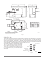
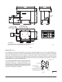
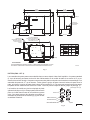
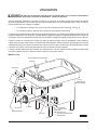
LEGS (FIGS. 1 & 2)
The four leg assemblies are packed in a separate carton for shipment. The standard legs (53/8" high) allow
the rim of the feed pan on the table model to be 27" above the table surface. These legs have neoprene
feet and require assembly. To assemble 53/8" high legs: Slide the Leg Stud through the Leg End Cap and
the Leg; then thread the Leg Stud into the base of the machine (Fig. 2). Do not overtighten; the legs need
only be hand-tight. Thread the Neoprene Foot into the Leg Stud (Fig. 2).
Floor model choppers are equipped with optional
18" or 21" legs. Each Leg is one piece and threads
into the base of the machine at the four corners.
These Legs can be adjusted by threading the Feet
in or out as necessary (Fig. 2) to level and stabilize
the chopper.
Fig. 1
Fig. 2
PL-56170
LEG (18" or 21")
LEG
LEG END CAP
LEG STUD
NEOPRENE FOOT FOOT
34"
INSIDE
5"
8-1/2"
4-3/8"
33-5/16"
DIM "B"
DIM "C"
DIM "A"
15-1/4"
4-1/16"
21"
INSIDE
17-3/8" 1-3/8"
20-1/8"
12-1/2"
1-5/16"
MACHINE HEIGHT FOR LEG OPTIONS
LEGS DIM "A"DIM "B"DIM "C"MODEL
5-3/8"
STD 10-3/4" 5-3/8" 4732
4732A
18"
OPT 23-3/8"18" 4732
4732A
21"
OPT 26-3/8"21" 4732
4732A
00-088182
ACCESS FOR
ELECTRICAL
POWER CONNECTION
WARNING
ELECTRICA
L & GROUNDING CONNECTIONS MUST COMPLY WITH
THE
APPLICABLE PORTIONS OF THE NATIONAL ELECTRICAL
CODE AND/OR OTHER LOCAL ELECTRICAL CODES.
(1-1/16 DIA HOLE)
FOR 3/4" TRADE SIZE CONDUIT
ELECTRICAL CONNECTION HOLE
ON/OFF SWITCH MAY BE
MOUNTED FOR RIGH HAND
OR LEFT HAND OPERATION
27"
27-3/8"
39-5/8"
40"
42-5/8"
43"

– 4 –
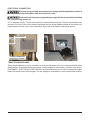
ELECTRICAL CONNECTION
Electrical and grounding connections must comply with the applicable portions of
the national electrical code and/or other local electrical codes.
Disconnect electrical power supply and place a tag at the disconnect switch indicating
the circuit is being worked on.
A 11/16" diameter hole for 3/4" trade size conduit is located in the bottom panel. Remove access panel from
the back of the unit. Refer to the machine data plate and the wiring diagram located on the machine for
proper sizing of branch circuit. Upon completion, fasten the access panel in place with screws.
THREE PHASE MACHINES
Three phase machines must be connected so that the attachment drive runs counterclockwise when
facing the hub. To check the direction of rotation, turn the chopper on momentarily. If rotation is not correct,
DISCONNECT ELECTRICAL POWER SUPPLY and interchange any two of the incoming power supply
leads. Reconnect power to the chopper. Turn the chopper on momentarily to verify correct motor rotation.
ACCESS PANEL
CONDUIT CONNECTOR
(Supplied by customer)

– 5 –
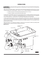
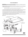
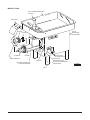
Fig. 3
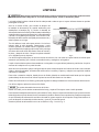
OPERATION
Do not operate without guard over feed opening. Do not put hands into feed opening.
Use feed stomper.
After cleaning, assemble chopper Cylinder, Worm, Knife, Plate and Adjusting Ring (and Feed Pan on model
4732A) as discussed in cleaning, page 7, and Fig. 3 or Fig. 4. Place the Deector over the Adjusting Ring.
• To start the chopper, pull the Start-Stop Switch Knob (Fig. 3 or Fig. 4).
• To stop the chopper, push the Start-Stop Switch Knob.
The neness of cut depends on the hole size of the chopper's Plate. The Knife and Plate must be kept clean
and sharp for a ne cut. The tightness of the Adjusting Ring does not regulate neness of cut; therefore
only moderate tightness is recommended. The Adjusting Ring should be only hand-tight.
Cut the meat into chunks about the size of a st and place in the Feed Pan. Feed meat under the guard
and into the Feed Pan opening. Use the Feed Stomper to dislodge over-sized pieces or to dislodge meat
which may become stuck in the Feed Pan opening or the cylinder opening. It is not necessary to force
meat through the chopper.
When the product is run through the chopper a second time, more speed is attained by feeding small
quantities at a time. Allow the machine to feed at its own rate.
MODEL 4732
PL-56289
FEED STOMPER
MACHINE DATA
PLATE
DEFLECTOR
CYLINDER
WORM
ADJUSTING RING
PLATE
KNIFE
PLUG BUTTON
OIL DRAIN PLUG
NON-REMOVABLE
FEED PAN
OIL-FILL PLUG
START - STOP
SWITCH KNOB

– 6 –
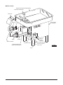
MODEL 4732A
Fig. 4
PL-56290
MACHINE DATA
PLATE
PLUG BUTTON
OIL DRAIN PLUG
OIL-FILL PLUG
FEED PAN
LOCKING KNOB START - STOP
SWITCH KNOB
FEED STOMPER
DEFLECTOR
CYLINDER
WORM
ADJUSTING RING
PLATE
KNIFE
REMOVABLE
FEED PAN

– 7 –
CLEANING
Disconnect electrical power supply and place a tag at the disconnect switch indicating
the circuit is being worked on before cleaning, servicing or removing parts.
The chopper should be thoroughly cleaned at the end of each day or any time it is not to be used for an
extended period of time.
On model 4732A only, rotate the Feed Pan Lock Knob
counterclockwise to unlock the pan (Fig. 5). Slide the
Feed Pan toward the chopping attachment until the
pan is free of the alignment brackets. Lift o the Feed
Pan and take it to a sink for cleaning. On model 4732,
the Feed Pan is permanently attached and must be
cleaned in place.
Pull the Deector straight up to remove it. Using the
spanner wrench, loosen the Adjusting Ring. Unscrew
and remove the Adjusting Ring with both hands. Hook
the spanner wrench around the Worm stud and pull the
Worm end out of the Cylinder. Remove the Knife and
Plate and then the Worm. Place the removed parts in
a sink for cleaning.
Using the spanner wrench, loosen but do not remove the cylinder nuts. With one hand on bottom of
Cylinder for support (it is heavy), turn the Cylinder clockwise and remove to a sink.
Thoroughly clean all removed parts in a sink using hot soapy water and sanitize them. Wipe machine
housing with a damp cloth.
Prior to reassembly, apply a light coating of tasteless mineral oil to the inside of the Cylinder, the threads
on the Cylinder and the Adjusting Ring, the Worm edges, the Knife and Plate and any other exposed
(non-plated) metal surfaces.
To reassemble the machine, rst install the Cylinder by rotating it counterclockwise until the ears are under
the cylinder nuts. Tighten the cylinder nuts nger-tight.
Slide the Worm into the Cylinder and rotate it to engage the square shank with the attachment drive.
With the spanner wrench, tighten the cylinder nuts.
Do not over-tighten the cylinder nuts.
Install the Knife (cutting edges out) and the Plate. Screw the Adjusting Ring on hand-tight.
To install the Feed Pan (model 4732A only), slide the alignment bracket (on the bottom of the pan) onto
the alignment foot on the chopper housing. Make a visual check to make sure the Feed Pan is squarely
on top of the machine. Push the Feed Pan Locking Knob in and rotate it 90o clockwise.
Store the Feed Stomper as shown in Fig. 3 or Fig. 4.
PL-41632-1
FEED PAN LOCK KNOB
Fig. 5

– 8 –
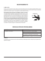
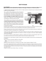
MAINTENANCE
LUBRICATION
During normal operation, gear case oil may require changing due to condensate mixing with the oil. Gear
case oil that has mixed with condensate water will have a milky brown color. If this is present, the oil
should be replaced.
To change the gear case oil, place a suitable catch pan under the
machine and remove the Drain Plug (Fig. 3 or Fig. 4). When old oil
is completely drained, replace the Drain Plug. Fill the gear case with
21 uid ounces of Mobil Spartan EP 460 as follows: Remove the Plug
Button (Fig. 3 or Fig. 4); then remove the Plastic Oil-Fill Plug (Fig.
6). Pour the proper amount of Mobil Spartan EP 460 into the elbow.
The gear case is full when the oil is at the bottom thread level of the
elbow (Fig. 6). Thread the Plastic Oil-Fill Plug back into the elbow,
nger-tight. Press the Plug Button back into the hole of the chopper
housing. The chopper requires no other lubrication maintenance.
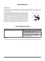
TROUBLESHOOTING
SYMPTOM POSSIBLE CAUSE
Chopper will not operate. Electrical power not connected.
Circuit Breaker tripped or fuse blown.
On model 4732A, removable pan is not
assembled properly; interlock is not engaged.
If the above suggestions do not remedy the
situation, contact Service.
SERVICE
Contact your local Hobart-authorized Service Oce for any repairs or adjustments needed on this equipment.
FORM 34747 Rev. C (April 2023) PRINTED IN U.S.A.
Fig. 6
PL-56171
PLASTIC OIL-FILL PLUG
FULL LINE

701 S. RIDGE AVENUE
TROY, OHIO 45373
937 332-3000
www.hobartcorp.com
PICADORAS 4732 Y 4732A
MODELO
4732 ML-18887 (PINTADO, BANDEJA NO DESMONTABLE)
ML-19282 (SST, BANDEJA NO DESMONTABLE)
ML-19809 (SST, BANDEJA NO DESMONTABLE)
4732A ML-19689 (PINTADO, BANDEJA DESMONTABLE)
ML-19690 (SST, BANDEJA DESMONTABLE)
PICADORA MODELO 4732
FORMULARIO 34747 Rev. C (Abril 2023)

– 2 –
Instalación, funcionamiento y cuidado de las
picadoras 4732 y 4732A
CONSERVE ESTAS INSTRUCCIONES
GENERAL
Las picadoras 4732 y 4732A están equipadas con un motor de 3 CV que hace girar el tornillo sinfín a 151 RPM. Los
modelos 4732 y 4732A están diseñados para utilizar una cuchilla y una placa del tamaño n.º 32. Incluyen cuchilla
Stay-Sharp y placa de molido de 1/8 pulg. de diámetro. Se pueden adquirir por separado otros tamaños de placas
de molido.
La bandeja de alimentación en acero inoxidable de la picadora 4732 no es desmontable y debe limpiarse in situ. El
modelo 4732A tiene una bandeja de alimentación desmontable en acero inoxidable y un interbloqueo que requiere
que la bandeja esté en su sitio antes de poder encender la máquina. En ambos modelos, hay un protector de
aluminio fundido montado permanentemente en la parte delantera y en los laterales de la bandeja de alimentación.
Las dimensiones de la bandeja de alimentación son 34 pulg. de largo x 21 pulg. de ancho x 5 pulg. de profundidad.
La carcasa del motor y del interruptor está disponible en acero pintado o en acero inoxidable. Los modelos de mesa
utilizan patas de 53/8 pulg. de altura que proporcionan una holgura de 8 pulg. entre la mesa y el punto más bajo del
anillo ajustador. Hay disponibles juegos de patas de otras alturas (18 o 21 pulg.) para convertir la picadora 4732 o
4732A en un modelo de suelo. Los embutidores para tripas de cerdo u oveja son accesorios disponibles.
La picadora puede triturar de 35 a 40 libras de carne de vacuno deshuesada por minuto, primer corte, mediante
una placa de 1/8 pulg. El rendimiento de molido del segundo corte es de 25 a 30 libras por minuto mediante una
placa de 1/8 pulg. La carne congelada debe atemperarse a 24 °F o más antes de molerla y puede estar en forma de
escamas o bastones.
INSTALACIÓN
DESEMBALAJE
La picadora fue inspeccionada antes de salir de la fábrica. El transportista asume total responsabilidad por la entrega
segura una vez aceptado el cargamento. Compruebe que no haya daños al cargamento inmediatamente después
de recibirlo.
Si la picadora está dañada, siga estos pasos:
1. Noticaraltransportistadentrodeloscincodíashábilessiguientesalafechaderecepción.
2. Noticardeinmediatoalaterminallocaldeltransportistatraseldescubrimiento(anotarlahora,lafechay
lapersonaconquiensehabló)yhacerunseguimientoyconrmaciónmediantecomunicacionesescritaso
electrónicas.
3. Conservar todos los materiales originales del embalaje por motivos de inspección.
4. Lapicadoranodebemoverse,instalarsenimodicarse.
5. NoticaralServiciodeAtenciónalClientedeHobartal(800)333-7447.
Retire el cartón de alrededor de la máquina. Retire los cuatro pernos que sujetan la máquina al patín. Desembale
el pisador de alimentación.
Antesdelainstalación,veriquequeelservicioeléctricocoincideconlasespecicacionesdelaplacadedatosde
la máquina.
Utilicelallaveinglesaparaaojarelanilloajustador.Desenrosqueyretireelanilloajustadorconambasmanos.
Retire y deseche la arandela de retención y la almohadilla de goma utilizadas en la parte delantera del tornillo sinfín,
donde se instalarán la cuchilla y la placa.
La picadora se debe limpiar y sanitizar completamente después de la instalación y antes de su uso. Consulte
LIMPIEZA (página 7).
© HOBART, 2023

– 3 –
PATAS (FIG. 1 Y 2)
Los conjuntos de cuatro patas se embalan en una caja de cartón separada para su envío. Las patas estándar (53/8
pulg.dealtura)permitenqueelbordedelabandejadealimentaciónquedea27pulg.porencimadelasupercie
de la mesa. Estas patas tienen pies de neopreno y requieren montaje. Para montar patas de 53/8 pulg. de altura:
Deslice el perno de la pata a través de la tapa del extremo y de la pata; a continuación, enrosque el perno en la base
de la máquina (Fig. 2). No apriete demasiado; las patas solo tienen que estar apretadas con la mano. Enrosque el
pie de neopreno en el perno de la pata (Fig. 2).
Los modelos de picadoras de suelo están equipados con
patas opcionales de 18 o 21 pulg. Cada pata es de una
sola pieza y se enrosca en la base de la máquina en las
cuatro esquinas. Estas patas pueden ajustarse enroscando
o desenroscando los pies según sea necesario (Fig. 2)
para nivelar y estabilizar la picadora.
Fig. 1
Fig. 2
PL-56170
PATA (18" o 21")
PATA
TAPA DE EXTREMO
DE LA PATA
PERNO DE LA PATA
PIE DE NEOPRENO PIE
34"
INTERIOR
5"
8-1/2"
4-3/8"
33-5/16"
DIM. "B" DIM. "C"
DIM. "A"
15-1/4"
4-1/16"
21"
INTERIOR
17-3/8" 1-3/8"
20-1/8"
12-1/2"
1-5/16"
ALTURA DE LA MÁQUINA PARA OPCIONES DE PATAS
PATAS DIM. "A" DIM. "B" DIM. "C"
MODELO
5-3/8" 10-3/4" 5-3/8" 4732
4732A
18" 23-3/8" 18" 4732
4732A
21" 26-3/8" 21" 4732
4732A
00-088182
ACCESO PARA
CONEXIÓN
ELÉCTRICA
ADVERTENCIA
LAS CONEXIONES ELÉCTRICAS Y A TIERRA DEBEN CUMPLIR CON LAS PARTES APLICABLES DEL
CÓDIGO ELÉCTRICO NACIONAL Y/O DE OTROS CÓDIGOS ELÉCTRICOS LOCALES.
ORIFICIO DE CONEXIÓN
ELÉCTRICA PARA CONDUCTO
DE TAMAÑO COMERCIAL 3/4"
(ORIFICIO DE 1-1/16 DE DIÁ.)
EL INTERRUPTOR DE
ENCENDIDO/APAGADO SE
PUEDE MONTAR PARA QUE
FUNCIONE A DERECHA O
IZQUIERDA
27"
27-3/8"
39-5/8"
40"
42-5/8"
43"
STD
OPC.
OPC.

– 4 –
CONEXIONES ELÉCTRICAS
ADVERTENCIA
Las conexiones eléctricas y a tierra deben cumplir con la parte correspondiente del Código
Eléctrico Nacional o de otros códigos eléctricos locales.
ADVERTENCIA
Desconecte la fuente de alimentación eléctrica y coloque una etiqueta en el interruptor de
desconexión para indicar que se están realizando trabajos en el circuito.
Enelpanelinferiorhayunoriciode11/16 pulg. de diámetro para conductos de 3/4 pulg. de tamaño comercial. Retire
el panel de acceso de la parte posterior de la unidad. Consulte la placa de datos de la máquina y el diagrama de
cableadosituadoenlamáquinaparadimensionarcorrectamenteelcircuitoderivado.Unavezterminado,jeel
panel de acceso en su sitio con tornillos.
MÁQUINAS TRIFÁSICAS
Las máquinas trifásicas deben conectarse de modo que el accionamiento del implemento gire en sentido antihorario
cuando esté orientado hacia el cubo. Para comprobar el sentido de giro, encienda la picadora momentáneamente. Si
la rotación no es correcta, DESCONECTE LA FUENTE DE ALIMENTACIÓN ELÉCTRICA e intercambie dos cables
cualesquiera de la fuente de alimentación de entrada. Vuelva a conectar la alimentación a la picadora. Encienda
momentáneamentelapicadoraparavericarlacorrectarotacióndelmotor.
PANEL DE ACCESO
CONECTOR DE CONDUCTOS
(Suministrado por el cliente)

– 5 –
Fig. 3
FUNCIONAMIENTO
ADVERTENCIA
No opere sin el protector sobre la abertura de alimentación. No introduzca las manos en
el oricio de alimentación. Utilice el pisador de alimentación.
Después de la limpieza, monte el cilindro picador, el tornillo sinfín, la cuchilla, la placa y el anillo ajustador (y la
bandeja de alimentación en el modelo 4732A) como se explica en Limpieza, página 7, y en la Fig. 3 o Fig. 4. Coloque
eldeectorsobreelanilloajustador.
- Para arrancar la picadora, tire de la perilla del interruptor de arranque-parada (Fig. 3 o Fig. 4).
- Para detener la picadora, presione el mando del interruptor de arranque-parada.
Lanuradelcortedependedeltamañodelosoriciosenlaplacadelapicadora.Lacuchillaylaplacadeben
mantenerselimpiasyaladasparaobteneruncorteno.Apretarelanilloajustadornoregulalanuradelcorte,por
lo que solo se recomienda un apriete moderado. El anillo ajustador solo debe apretarse con la mano.
Corte la carne en trozos del tamaño de un puño y coloque los trozos en la bandeja de alimentación. Introduzca la
carne por debajo del protector y en la abertura de la bandeja. Utilice el pisador de alimentación para rechazar piezas
de carne demasiado grandes o carne que pueda quedar atascada en la abertura de la bandeja de alimentación o
en la abertura del cilindro. No es necesario forzar la carne a través de la picadora.
Cuando el producto pasa por la picadora una segunda vez, se consigue más velocidad alimentando pequeñas
cantidades cada vez. Deje que la máquina avance a su propio ritmo.
MODELO 4732
PL-56289
PISADOR DE ALIMENTACIÓN
PLACA DE DATOS
DE LA MÁQUINA
DEFLECTOR
CILINDRO
SINFÍN
ANILLO AJUSTADOR
PLACA
CUCHILLA
BOTÓN DEL TAPÓN
TAPÓN DE
VACIADO DE
ACEITE
BANDEJA DE ALIMENTACIÓN NO DESMONTABLE
TAPÓN DE LLENADO DE ACEITE
PERILLA DE CONTROL START - STOP

– 6 –
MODELO 4732A
Fig. 4
PL-56290
PLACA DE DATOS
DE LA MÁQUINA
BOTÓN DEL TAPÓN
TAPÓN DE
VACIADO
DE ACEITE
TAPÓN DE LLENADO DE ACEITE
POMO DE BLOQUEO DE LA
BANDEJA DE ALIMENTACIÓN
PERILLA DE CONTROL
START - STOP
PISADOR DE ALIMENTACIÓN
DEFLECTOR
CILINDRO
SINFÍN
ANILLO AJUSTADOR
PLACA
CUCHILLA
BANDEJA DE ALIMENTACIÓN DESMONTABLE

– 7 –
LIMPIEZA
ADVERTENCIA
Desconecte la alimentación eléctrica y coloque una etiqueta en el interruptor de desconexión
indicando que se está trabajando en el circuito antes de limpiar, revisar o desmontar piezas.
Lapicadoradebelimpiarseafondoalnaldecadajornadaocadavezquenovayaautilizarseduranteunperiodo
prolongado de tiempo.
Solo en el modelo 4732A, gire el botón de bloqueo de
la bandeja de alimentación en sentido antihorario para
desbloquear la bandeja (Fig. 5). Deslice la bandeja de
alimentación hacia el accesorio picador hasta que la bandeja
quede libre de los soportes de alineación. Levante la bandeja
y llévela a un fregadero para limpiarla. En el modelo 4732,
labandejadealimentaciónestájadapermanentementey
debe limpiarse en su lugar.
Tiredeldeector hacia arribapara retirarlo. Conlallave
inglesa, aoje el anillo ajustador. Desenrosque y retire
el anillo ajustador con ambas manos. Enganche la llave
inglesa alrededor del espárrago del tornillo sinfín y extraiga
el extremo del tornillo sinfín del cilindro. Retire la cuchilla y
la placa, y después el sinfín. Coloque las piezas retiradas
en un fregadero para su limpieza.
Conlallaveinglesa,aojeperonoretirelastuercasdelcilindro.Conunamanoenlaparteinferiordelcilindropara
sostenerlo (es pesado), gire el cilindro en sentido horario y extráigalo a un fregadero.
Limpie a fondo todas las piezas desmontadas en un fregadero con agua caliente jabonosa y sanitícelas. Limpie la
carcasa de la máquina con un paño húmedo.
Antes de volver a montarlo, aplique una ligera capa de aceite mineral insípido en el interior del cilindro, las roscas del
cilindroydelanilloajustador,losbordesdeltornillosinfín,lacuchillaylaplaca,ycualquierotrasuperciemetálica
expuesta (no chapada).
Para volver a montar la máquina, instale primero el cilindro girándolo en sentido antihorario hasta que las orejetas
queden debajo de las tuercas del cilindro. Apriete las tuercas del cilindro con los dedos.
Deslice el tornillo sinfín en el cilindro y gírelo para engranar el vástago cuadrado con el accionamiento del accesorio.
Con la llave inglesa, apriete las tuercas del cilindro.
AVISO
No apriete demasiado las tuercas del cilindro.
Instale la cuchilla (con los bordes cortantes hacia fuera) y la placa. Enrosque a mano el anillo ajustador.
Para instalar la bandeja de alimentación (solo modelo 4732A), deslice el soporte de alineación (en la parte inferior de
la bandeja) sobre el pie de alineación de la carcasa de la picadora. Realice una comprobación visual para asegurarse
de que la bandeja de alimentación está bien colocada en la parte superior de la máquina. Empuje hacia dentro el
pomo de bloqueo de la bandeja de alimentación y gírelo 90o en sentido horario.
Guarde el pisador de alimentación como se muestra en la Fig. 3 o en la Fig. 4.
PL-41632-1
POMO DE BLOQUEO DE LA BANDEJA DE ALIMENTACIÓN
Fig. 5

– 8 –
MANTENIMIENTO
LUBRICACIÓN
Durante el funcionamiento normal, puede ser necesario cambiar el aceite de la caja de engranajes debido a que el
condensado se mezcla con el aceite. El aceite de la caja de engranajes que se haya mezclado con agua condensada
tendrá un color marrón lechoso. Si está presente, debe sustituirse el aceite.
Para cambiar el aceite de la caja de engranajes, coloque un recipiente
adecuado debajo de la máquina y retire el tapón de vaciado (Fig. 3 o Fig.
4). Cuando el aceite usado esté completamente drenado, vuelva a colocar
el tapón de vaciado. Llene la caja de engranajes con 21 onzas líquidas de
Mobil Spartan EP 460 como se indica a continuación: Retire el botón del
tapón (Fig. 3 o Fig. 4); a continuación, retire el tapón de plástico de llenado
de aceite (Fig. 6). Vierta la cantidad adecuada de Mobil Spartan EP 460 en
el codo. La caja de engranajes está llena cuando el aceite está al nivel de
la rosca inferior del codo (Fig. 6). Vuelva a enroscar el tapón de plástico
para llenado de aceite en el codo, apretándolo con los dedos. Vuelva a
introducirelbotóndeltapóneneloriciodelacarcasa delapicadora.
La picadora no requiere ningún otro mantenimiento de lubricación.
RESOLUCIÓN DE PROBLEMAS
PROBLEMA CAUSA POSIBLE
La picadora no funcionará. El cable de alimentación no está conectado.
El disyuntor se disparó o el fusible se quemó.
En el modelo 4732A, la bandeja desmontable no está
bien instalada; el interbloqueo no está activado.
Si las sugerencias anteriores no solucionan el
problema, póngase en contacto con el servicio técnico.
SERVICIO
ComuníqueseconlaocinadeserviciolocalautorizadaporHobartparasolicitarcualquiertipodereparacioneso
ajustes a su equipo.
FORMULARIO 34747 Rev. C (abril de 2023) IMPRESO EN EE. UU.
Fig. 6
PL-56171
LÍNEA
COMPLETA
TAPÓN DE PLÁSTICO
DE LLENADO DE ACEITE

701 S. RIDGE AVENUE
TROY, OHIO 45373
937 332-3000
www.hobartcorp.com
HACHOIRS 4732 ET 4732A
MODÈLE
4732 ML-18887 (BAC PEINT, NON AMOVIBLE)
ML-19282 (SST, BAC NON AMOVIBLE)
ML-19809 (SST, BAC NON AMOVIBLE)
4732A ML-19689 (BAC PEINT, AMOVIBLE)
ML-19690 (SST, BAC AMOVIBLE)
HACHOIR MODÈLE 4732
FORMULAIRE 34747 Rév. C (avril 2023)

– 2 –
Installation, utilisation et entretien des
Hachoirs 4732 et 4732A
CONSERVEZ CES INSTRUCTIONS
RENSEIGNEMENTS GÉNÉRAUX
Les hachoirs 4732 et 4732A sont équipés d’un moteur de 3 HP qui fait tourner la vis sans n à 151 tr/min. Les
modèles 4732 et 4732A sont conçus pour utiliser un couteau et une plaque de taille nº 32. Comprend un couteau
Stay-Sharp et une plaque de hachage de diamètre de 1/8 po. Des plaques de hachage supplémentaires de diverses
tailles peuvent être achetées séparément.
Le bac d’alimentation en acier inoxydable du modèle 4732 n’est pas amovible et doit être nettoyé sur place. Le
modèle 4732A est doté d’un bac d’alimentation amovible en acier inoxydable et d’un dispositif de verrouillage
qui nécessite que le bac d’alimentation soit en place avant que la machine puisse être mise en marche. Sur les
deux modèles, un protège-main en fonte d’aluminium est monté en permanence à l’avant et sur les côtés du bac
d’alimentation. Les dimensions du bac d’alimentation sont : 34 po x 21 po x 5 po (long. x larg. x prof.). Le boîtier du
moteur et de l’interrupteur est disponible en acier peint ou en acier inoxydable. Les modèles de table comprennent
des pattes de 5 3/8 po en hauteur ce qui orent un dégagement de 8 po entre la table et le point le plus bas de la
bague de réglage. Des ensembles de pattes d’autres hauteurs (18 po ou 21 po) sont disponibles pour convertir le
modèle 4732 ou le modèle 4732A en un modèle sur pied. Des poussoirs à saucisses pour boyaux de porc ou de
mouton sont des accessoires disponibles.
Le hachoir peut broyer 35 à 40 livres de bœuf désossé par minute, première coupe, au moyen d’une plaque de 1/8
po. Le taux de broyage de la deuxième coupe est de 25 à 30 livres par minute au moyen d’une plaque de 1/8 po.
La viande congelée doit être décongelée à une température de 24 °F ou supérieure avant d’eectuer le broyage et
peut être sous forme de miettes ou de bâtonnets.
INSTALLATION
DÉBALLAGE
Ce hachoir a été inspecté avant de quitter l’usine. La société de transport assume l’entière responsabilité de la
livraison en bon état du fait de l’acceptation de l’expédition. Inspectez la scie à viande dès sa réception pour des
bris dus au transport.
Si vous constatez que le hachoir est endommagé, procédez comme suit :
1. La société de transport doit être notiée dans les cinq jours ouvrables suivant la réception du robot culinaire.
2. La société de transport doit être notiée immédiatement une fois le dommage constaté (notez l’heure, la date
et la personne de contact), et faites un suivi de la notication et conrmez-la au moyen de communication
écrite ou électronique.
3. Tous les matériaux d’emballage originaux doivent être conservés aux ns d’inspection.
4. La hachoir ne peut pas avoir été déplacé, installé ou modié.
5. Communiquez avec le service à la clientèle de Hobart au 800 333-7447.
Retirez le carton autour de la machine. Retirez les quatre boulons retenant la machine au patin. Déballez le poussoir.
Avant d’installer le batteur-mélangeur, vériez que le service électrique est conforme aux spécications sur la plaque
signalétique de l’appareil.
Utilisez la clé à molette pour desserrer la bague de réglage. Dévissez et retirez la bague de réglage à deux mains.
Retirez et jetez la rondelle de retenue et le tampon en caoutchouc utilisés à l’avant de la vis sans n où le couteau
et la plaque doivent être installés.
La hachoir doit être soigneusement nettoyé et désinfecté après l’installation et avant d’être utilisé. Reportez-vous à
la section NETTOYAGE (page 7).
© HOBART, 2023

– 3 –
PATTES (FIGS. 1 ET 2).
Les ensembles de quatre pattes sont emballés dans un carton séparé à des ns d’expédition. Les pattes standard
(5 3/8 po de hauteur) permettent au bord du bac d’alimentation sur le modèle de table de se trouver à 27 po au-
dessus de la surface du table. Ces pattes comprennent des pieds en néoprène et nécessitent un assemblage. Pour
assembler les pattes de 5 3/8 po en hauteur : Faites glisser le goujon de patte à travers l’embout de patte et sur la
patte; puis vissez le goujon de patte dans la base de la machine (g. 2). Ne serrez pas excessivement les pattes;
les pattes doivent seulement être serrées à la main. Vissez le pied en néoprène dans le goujon de patte (g. 2).
Les hachoirs de modèle sur pied sont équipés de pieds
optionnels de 18 po ou 21 po. Chaque patte est d’une seule
pièce et s’enle dans la base de la machine aux quatre
coins. Ces pattes peuvent être ajustées en enlant ou
dévissant les pieds selon les besoins (g. 2) pour niveler
et stabiliser le hachoir.
Fig. 1
Fig. 2
PL-56170
PATTE (18 po ou 21 po)
PATTE
EMBOUT DE PATTE
GOUJON DE PATTE
PIED EN NÉOPRÈNE PIED
34 po
INTÉRIEUR
5 po
8 1/2 po
4 3/8 po
33 5/16 po
DIM « B » DIM « C »
DIM « A »
15 1/4 po
4 1/16 po
21 po
INTÉRIEUR
17 3/8 po 1 3/8 po
20 1/8 po
12 1/2 po
1 5/16 po
HAUTEUR DE LA MACHINE POUR LES OPTIONS DE PATTES
PATTES DIM « A » DIM « B » DIM « C »
MODÈLE
5 3/8 po 10 3/4 po 5 3/8 po 4732
4732A
18 po 23 3/8 po 18 po 4732
4732A
21 po 26 3/8 po 21 po 4732
4732A
00-088182
ACCÈS POUR
RACCORDEMENT
ÉLECTRIQUE
AVERTISSEMENT
LES RACCORDEMENTS ÉLECTRIQUES ET DE MISE À LA TERRE DOIVENT ÊTRE CONFORMES À LA PARTIE
APPLICABLE DU CODE NATIONAL DE L’ÉLECTRICITÉ OU DES AUTRES CODES ÉLECTRIQUES LOCAUX.
TROU DE RACCORDEMENT
ÉLECTRIQUE POUR CONDUIT DE
TAILLE COMMERCIALE 3/4 po
(TROU DE DIA. DE 1 1/16 po)
L’INTERRUPTEUR
MARCHE/ARRÊT PEUT ÊTRE
MONTÉ POUR UNE MAIN
DROITE OU UNE MAIN
GAUCHE
27 po
27 3/8 po
39 5/8 po
40 po
42 5/8 po
43 po
STD
OPT
OPT

– 4 –
RACCORDEMENTS ÉLECTRIQUES
AVERTISSEMENT
Les raccordements électriques et de mise à la terre doivent être conformes aux parties
pertinentes du National Electrical Code ou autres codes électriques locaux.
AVERTISSEMENT
Coupez l’alimentation électrique et placez une étiquette sur le sectionneur indiquant que le
circuit est en cours de traitement.
Un trou de diamètre de 1/16 po pour la conduite de taille commerciale de 3/4 po est situé sur le panneau inférieur.
Retirez le panneau d’accès à l’arrière de l’appareil. Reportez-vous à la plaque signalétique de la machine et au
schéma de câblage situés sur la machine pour le dimensionnement correct du circuit de dérivation. Une fois terminé,
xez le panneau d’accès en place au moyen des vis.
MACHINES TRIPHASÉES
Les machines triphasées doivent être connectées de manière à ce que l’entraînement de l’accessoire tourne dans le
sens antihoraire face au moyeu. Pour vérier le sens de rotation, mettez sous tension momentanément le hachoir. Si
la rotation n’est pas correcte, COUPEZ L’ALIMENTATION ÉLECTRIQUE et échangez deux des câbles d’alimentation
entrants. Rétablissez l’alimentation au hachoir. Mettez sous tension momentanément le hachoir pour vérier que
la rotation du moteur est correcte.
PANNEAU D’ACCÈS
RACCORD DE CONDUITE
(Fourni par le client)
A página está carregando...
A página está carregando...
A página está carregando...
A página está carregando...
-
 1
1
-
 2
2
-
 3
3
-
 4
4
-
 5
5
-
 6
6
-
 7
7
-
 8
8
-
 9
9
-
 10
10
-
 11
11
-
 12
12
-
 13
13
-
 14
14
-
 15
15
-
 16
16
-
 17
17
-
 18
18
-
 19
19
-
 20
20
-
 21
21
-
 22
22
-
 23
23
-
 24
24


em outras línguas
- español: Hobart 4732(A) Chopper Manual de usuario
- français: Hobart 4732(A) Chopper Manuel utilisateur
- English: Hobart 4732(A) Chopper User manual
Artigos relacionados
Outros documentos
-
Mega Spartan IV Battle Pack - 97208 Building Instructions
-
Moulinex HV8 ME683832 Manual do usuário
-
Tefal FP413DAE Manual do usuário
-
Kenwood FP910 Manual do proprietário
-
-
-
Bodum 11514 Manual do usuário
-