Danfoss VLT Compressor Drive CDS 803 Guia de usuario
- Tipo
- Guia de usuario

Operating Guide
VLT® Compressor Drive CDS 803
drives.danfoss.com


1
1.1
1.2
1.3
1.4
1.5
1.6
2
2.1
2.2
2.3
2.4
3
3.1
3.1.1
3.1.2
3.1.3
3.2
3.2.1
3.2.2
3.2.3
3.2.3.1
3.2.3.2
3.2.3.3
3.2.3.4
3.2.4
3.2.4.1
3.2.4.2
3.2.4.3
3.2.4.4
3.2.4.5
3.2.5
3.2.6
3.2.6.1
3.2.6.2
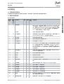
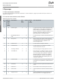
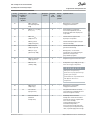
Contents
Introduction 5
Purpose of this Operating Guide 5
Trademarks 5
Additional Resources 5
Manual and Software Version 5
Type Approvals and Certications 5
Disposal 5
Safety 7
Safety Symbols 7
Qualied Personnel 7
Safety Precautions 7
Motor Thermal Protection 8
Installation 9
Mechanical Installation 9
Cooling Capacity 9
Side-by-side Installation 9
Drive Dimensions 10
Electrical Installation 11
Electrical Installation in General 11
IT Grid 11
Mains and Motor Connection 11
Introduction 11
Connecting to Mains and Motor 12
Relays and Terminals on Enclosure Sizes H3–H5 14
Relays and Terminals on Enclosure Size H6 15
Fuses and Circuit Breakers 15
Branch Circuit Protection 15
Short-circuit Protection 15
Overcurrent Protection 15
UL/Non-UL Compliance 15
Recommendation of Fuses 16
EMC-correct Electrical Installation 16
Control Terminals 18
Accessing the Control Terminals 18
Setting the Control Terminals to Run the Compressor 18
AQ32174876762701-000101/130R0627 | 3Danfoss A/S © 2019.12
Contents
VLT® Compressor Drive CDS 803
Operating Guide
American English

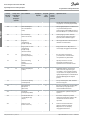
3.2.7
4
4.1
4.2
4.3
4.4
4.5
4.6
4.7
4.8
5
5.1
5.2
6
6.1
6.2
6.3
6.4
6.4.1
6.4.2
6.5
6.5.1
6.5.2
6.5.3
6.5.4
6.5.5
6.5.6
6.5.7
6.5.8
6.5.9
6.5.10
6.5.11
6.5.12
6.5.13
6.5.14
6.6
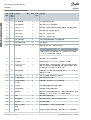
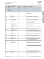
Electrical Wiring 19
Programming 20
Local Control Panel (LCP) 20
Start-up Quick Guide for Open-loop Applications 21
Start-up Quick Guide for Compressor Functions 23
Start-up Quick Guide for Compressor Closed-loop Applications 24
Changes Made 27
Changing Parameter Settings 27
Accessing All Parameter via the Main Menu 27
Main Menu Structure 28
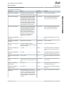
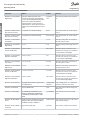
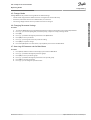
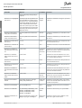
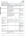
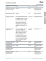
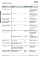
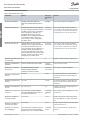
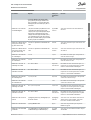
Troubleshooting 29
Acoustic Noise or Vibration 29
List of Warnings and Alarms 29
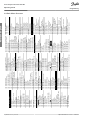
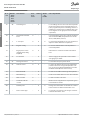
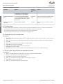
Specications 32
Mains Supply 3x200–240 V AC 32
Mains Supply 3x380–480 V AC 32
EMC Emission Test Results 33
Special Conditions 34
Derating for Ambient Temperature and Switching Frequency 34
Derating for Low Air Pressure and High Altitudes 34
General Technical Data 34
Protection and Features 34
Mains Supply (L1, L2, L3) 35
Compressor Output (U, V, W) 35
Cable Lengths and Cross-sections 35
Digital Inputs 35
Analog Inputs 35
Analog Outputs 36
Digital Outputs 36
Control Card, RS485 Serial Communication 36
Control Card, 24 V DC Output 36
Relay Outputs, Enclosure Sizes H3–H5 36
Relay Outputs, Enclosure Size H6 37
Control Card, 10 V DC Output 37
Ambient Conditions 37
Options for VLT® Compressor Drive CDS 803 38
AQ32174876762701-000101/130R06274 | Danfoss A/S © 2019.12
Contents
VLT® Compressor Drive CDS 803
Operating Guide
American English

•
•
•
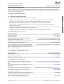
1 Introduction
1.1 Purpose of this Operating Guide
This operating guide provides information for safe installation and commissioning of the AC drive. It is intended for use by qualied
personnel. Read and follow the instructions to use the drive safely and professionally. Pay particular attention to the safety instruc-
tions and general warnings. Always keep this operating guide available with the drive.
1.2 Trademarks
VLT
®
is a registered trademark for Danfoss A/S.
1.3 Additional Resources
Other resources are available to understand advanced drive functions and programming.
The programming guide provides greater detail on working with parameters and shows many application examples.
The design guide provides detailed information about capabilities and functionality to design motor control systems.
Supplementary publications and manuals are available from Danfoss .
See www.danfoss.com for supplementary documentation.
VLT® Motion Control Tool MCT 10 software support
Download the software from the Service and Support download page on www.danfoss.com.
During the installation process of the software, enter CD-key 34544400 to activate the CDS 803 functionality. An activation key is
not required for using the CDS 803 functionality.
The latest software does not always contain the latest updates for the drive. Contact the local sales oce for the latest drive updates
(in the form of *.upd les), or download the drive updates from the Service and Support download page on www.danfoss.com.
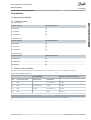
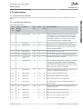
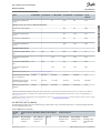
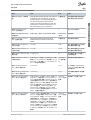
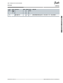
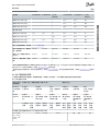
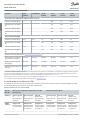
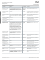
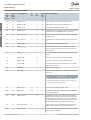
1.4 Manual and Software Version
This manual is regularly reviewed and updated. All suggestions for improvement are welcome.
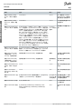
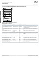
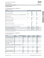
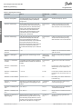
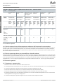
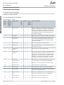
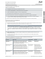
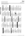
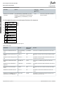
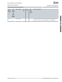
Table 1: Manual and Software Version
Edition
Remarks
Software version
AQ321748767627xx-xx0101
New power sizes added to product range.
6.0–10 kW (8–15 hp): Version 2.0
18–30 kW (25–40 hp): Version 1.00
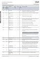
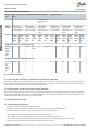
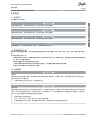
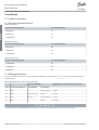
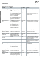
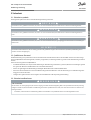
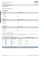
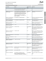
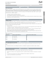
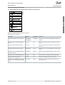
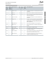
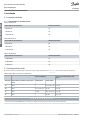
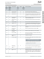
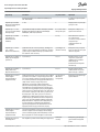
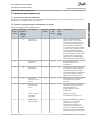
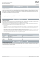
1.5 Type Approvals and Certications
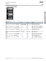
The following list is a selection of possible type approvals and certications for VLT® Compressor Drive CDS 803 drives:
Name of certication
Certication logo
IP20
EC Declaration of Conformity
✓
UL listed
✓
UL recognized (only valid for CDS 803 - S096)
✓
RCM
✓
EAC
✓
UkrSEPRO
089
✓
VLT® Compressor Drive CDS 803 drives having S096 in the type code (400 V AC, 18.5–30 kW (25–40 hp)) are certied to UL/EN/IEC
60730-1. The drive is also designed for systems that have to be compliant with UL/IEC/EN 60335.
For more information on UL 508C thermal memory retention requirements, refer to the section Motor Thermal Protection in the
product-specic design guide.
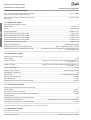
1.6 Disposal
Do not dispose of equipment containing electrical components together with domestic waste.
AQ32174876762701-000101 / 130R0627 | 5Danfoss A/S © 2019.12
Introduction
VLT® Compressor Drive CDS 803
Operating Guide
American English

Collect it separately in accordance with local and currently valid legislation.
AQ32174876762701-000101 / 130R06276 | Danfoss A/S © | 2019.12
Introduction
VLT® Compressor Drive CDS 803
Operating Guide
American English

•
•
•
•
-
-
-
-
2 Safety
2.1 Safety Symbols
The following symbols are used in this manual:
D A N G E R
Indicates a hazardous situation which, if not avoided, will result in death or serious injury.
W A R N I N G
Indicates a hazardous situation which, if not avoided, could result in death or serious injury.
C A U T I O N
Indicates a hazardous situation which, if not avoided, could result in minor or moderate injury.
N O T I C E
Indicates information considered important, but not hazard-related (for example, messages relating to property damage).
2.2 Qualied Personnel
To allow trouble-free and safe operation of the unit, only qualied personnel with proven skills are allowed to transport, store, as-
semble, install, program, commission, maintain, and decommission this equipment.
Persons with proven skills:
Are qualied electrical engineers, or persons who have received training from qualied electrical engineers and are suitably ex-
perienced to operate devices, systems, plant, and machinery in accordance with pertinent laws and regulations.
Are familiar with the basic regulations concerning health and safety/accident prevention.
Have read and understood the safety guidelines given in all manuals provided with the unit, especially the instructions given in
the Operating Guide.
Have good knowledge of the generic and specialist standards applicable to the specic application.
2.3 Safety Precautions
W A R N I N G
HIGH VOLTAGE
AC drives contain high voltage when connected to AC mains input, DC supply, or load sharing. Failure to perform installation,
start-up, and maintenance by qualied personnel can result in death or serious injury.
Only qualied personnel must perform installation, start-up, and maintenance.
W A R N I N G
UNINTENDED START
When the drive is connected to AC mains, DC supply, or load sharing, the motor may start at any time. Unintended start during
programming, service, or repair work can result in death, serious injury, or property damage. Start the motor with an external
switch, a eldbus command, an input reference signal from the local control panel (LCP), via remote operation using MCT 10 soft-
ware, or after a cleared fault condition.
Disconnect the drive from the mains.
Press [O/Reset] on the LCP before programming parameters.
Ensure that the drive is fully wired and assembled when it is connected to AC mains, DC supply, or load sharing.
AQ32174876762701-000101 / 130R0627 | 7Danfoss A/S © 2019.12
Safety
VLT® Compressor Drive CDS 803
Operating Guide
American English

1.
-
-
-
-
-
-
-
-
-
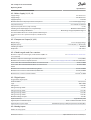
W A R N I N G
DISCHARGE TIME
The drive contains DC-link capacitors, which can remain charged even when the drive is not powered. High voltage can be
present even when the warning indicator lights are o.
Failure to wait the specied time after power has been removed before performing service or repair work could result in death or
serious injury.
Stop the motor.
Disconnect AC mains, permanent magnet type motors, and remote DC-link supplies, including battery back-ups, UPS, and
DC-link connections to other drives.
Wait for the capacitors to discharge fully. The minimum waiting time is specied in the table Discharge time and is also visible
on the nameplate on top of the drive.
Before performing any service or repair work, use an appropriate voltage measuring device to make sure that the capacitors
are fully discharged.
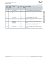
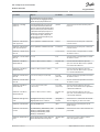
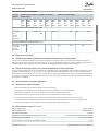
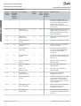
Table 2: Discharge Time
Voltage [V]
Power range [kW (hp)]
Minimum waiting time (minutes)
3x200
6.0–10 (8.0–15)
15
3x400
6.0–7.5 (8.0–10)
4
3x400
10–30 (15–40)
15
W A R N I N G
LEAKAGE CURRENT HAZARD
Leakage currents exceed 3.5 mA. Failure to ground the drive properly can result in death or serious injury.
Ensure the correct grounding of the equipment by a certied electrical installer.
W A R N I N G
EQUIPMENT HAZARD
Contact with rotating shafts and electrical equipment can result in death or serious injury.
Ensure that only trained and qualied personnel perform installation, start-up, and maintenance.
Ensure that electrical work conforms to national and local electrical codes.
Follow the procedures in this manual.
C A U T I O N
INTERNAL FAILURE HAZARD
An internal failure in the drive can result in serious injury when the drive is not properly closed.
Ensure that all safety covers are in place and securely fastened before applying power.
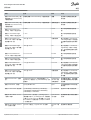
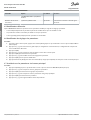
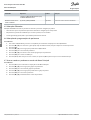
2.4 Motor Thermal Protection
This procedure is only valid for VLT® Compressor Drive CDS 803 - S096 (18.2–30 kW/VZH088–VZH170))
Procedure
Set parameter 1-90 Motor Thermal Protection to [4] ETR trip 1 to enable the motor thermal protection function.
AQ32174876762701-000101 / 130R06278 | Danfoss A/S © | 2019.12
Safety
VLT® Compressor Drive CDS 803
Operating Guide
American English

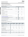
3 Installation
3.1 Mechanical Installation
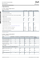
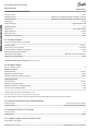
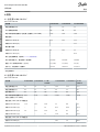
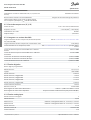
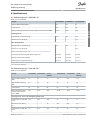
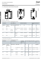
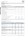
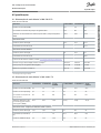
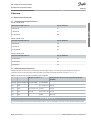
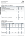
3.1.1 Cooling Capacity
Table 3: H3–H4, 400 V
Cooling capacity
400 V IP20 enclosure
4 TR/VZH028
H3
5 TR/VZH035
H3
6.5 TR/VZH044
H4
Table 4: H4–H5, 200 V
Cooling capacity
200 V IP20 enclosure
4 TR/VZH028
H4
5 TR/VZH035
H4
6.5 TR/VZH044
H5
Table 5: H5–H6, 400 V
Cooling capacity
400 V IP20 enclosure
13 TR/VZH088
H5
17 TR/VZH117
H5
26 TRVZH170
H6
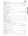
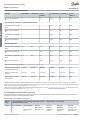
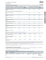
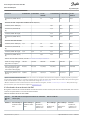
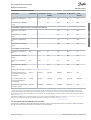
3.1.2 Side-by-side Installation
The drive can be mounted side by side but requires the clearance specied in Table 6 above and below for cooling.
Table 6: Clearance Required for Cooling
Power [kW (hp)]
Clearance above/below [mm (in)]
Size
IP protection rating
3x200–240 V
3x380–480 V
H3
IP20
–
6.0–7.5 (8.0–10)
100 (4)
H4
IP20
6.0–7.5 (8.0–10)
10 (15)
100 (4)
H5
IP20
10 (15)
18.5–22 (25–30)
100 (4)
H6
IP20
–
30(40)
200 (7.9)
N O T I C E
With IP21/NEMA Type1 option kit mounted, a distance of 50 mm (2 in) between the units is required.
AQ32174876762701-000101 / 130R0627 | 9Danfoss A/S © 2019.12
Installation
VLT® Compressor Drive CDS 803
Operating Guide
American English

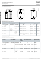
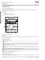
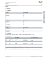
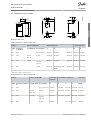
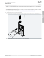
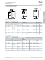
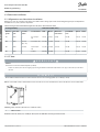
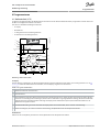
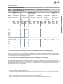
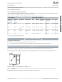
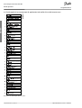
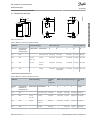
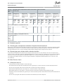
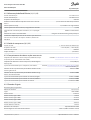
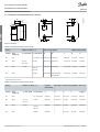
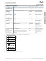
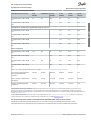
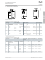
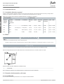
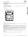
3.1.3 Drive Dimensions
e
f
a
e
e
f
a
d
e
A
a
b
B
C
D
e30bf984.10
Illustration 1: Dimensions
Table 7: Dimensions, Enclosure Sizes H3–H6
Enclosure
Power [kW (hp)]
Height [mm (in)]
Width [mm (in)]
Size
IP protection
rating
3x200–240 V
3x380–480 V
A
A
(1)
a
B
b
H3
IP20
–
6.0–7.5 (8.0–10)
255 (10.0)
329 (13.0)
240 (9.4)
100 (3.9)
74 (2.9)
H4
IP20
6.0–7.5
(8.0–10)
10 (15)
296 (11.7)
359 (14.1)
275 (10.8)
135 (5.3)
105 (4.1)
H5
IP20
10 (15)
18.5–22
(25–30)
334 (13.1)
402 (15.8)
314 (12.4)
150 (5.9)
120 (4.7)
H6
IP20
–
30 (40)
518 (20.4)
595 (23.4)/635 (25),
45 kW
495 (19.5)
239 (9.4)
200 (7.9)
1
Including decoupling plate.
Table 8: Dimensions, Enclosure Sizes H3–H6
Enclosure
Power [kW (hp)]
Depth
[mm (in)]
Mounting hole [mm (in)]
Maximum weight
Size
IP protection rat-
ing
3x200–240 V
3x380–480 V
C
d
e
f
kg (lb)
H3
IP20
–
6.0–7.5 (8.0–10)
206 (8.1)
11 (0.43)
5.5 (0.22)
8.1 (0.32)
4.5 (9.9)
H4
IP20
6.0–7.5
(8.0–10)
11 (15)
241 (9.5)
12.6 (0.50)
7 (0.28)
8.4 (0.33)
7.9 (17.4)
H5
IP20
11 (15)
18.5–22
(25–30)
255 (10)
12.6 (0.50)
7 (0.28)
8.5 (0.33)
9.5 (20.9)
H6
IP20
–
30 (40)
242 (9.5)
–
8.5 (0.33)
15 (0.6)
24.5 (54)
AQ32174876762701-000101 / 130R062710 | Danfoss A/S © | 2019.12
Installation
VLT® Compressor Drive CDS 803
Operating Guide
American English

-
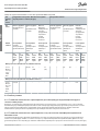
3.2 Electrical Installation
3.2.1 Electrical Installation in General
All cabling must comply with national and local regulations on cable cross-sections and ambient temperature. Copper conductors
are required. 75 °C (167 °F) is recommended.
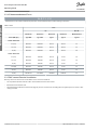
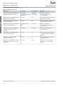
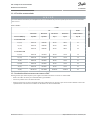
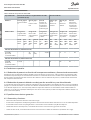
Table 9: Tightening Torques for Enclosure Sizes H3–H6, 3x200–240 V & 3x380–480 V
Power [kW (hp)]
Torque [Nm (in-lb)]
Enclo-
sure size
IP protec-
tion rating
3x200–240 V
3x380–480 V
Mains
Motor
DC connec-
tion
Control ter-
minals
Ground
Relay
H3
IP20
–
6.0–7.5 (8.0–10)
0.8 (7)
0.8 (7)
0.8 (7)
0.5 (4)
0.8 (7)
0.5 (4)
H4
IP20
6.0–7.5 (8.0–
10)
10–15 (15–20)
1.2 (11)
1.2 (11)
1.2 (11)
0.5 (4)
0.8 (7)
0.5 (4)
H5
IP20
10 (15)
18.5–22 (25–30)
1.2 (11)
1.2 (11)
1.2 (11)
0.5 (4)
0.8 (7)
0.5 (4)
H6
IP20
–
30 (40)
4.5 (40)
4.5 (40)
–
0.5 (4)
3 (27)
0.5 (4)
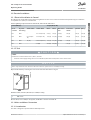
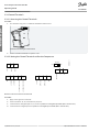
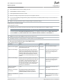
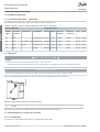
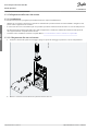
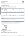
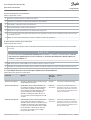
3.2.2 IT Grid
C A U T I O N
IT GRID
Installation on isolated mains source, that is, IT mains.
Ensure that the supply voltage does not exceed 440 V (3x380–480 V units) when connected to mains.
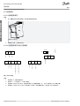
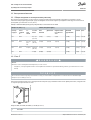
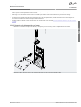
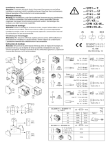
N O T I C E
This is only relevant for 200–240 V and 380–400 V drives in power sizes 6.0–10 kW (8.0–15 hp).
Open the RFI switch by removing the screw on the side of the drive when at IT grid.
e30bb612.10
1
Illustration 2: IP20, 200–240 V, 380–480 V, 6.0–10 kW (8.0–15 hp)
1
EMC screw
On 380–480 V, 18.5–30 kW (25–40 hp) units, the RFI lter cannot be switched o.
3.2.3 Mains and Motor Connection
3.2.3.1 Introduction
The drive is designed to operate Danfoss VZH Compressors.
AQ32174876762701-000101 / 130R0627 | 11Danfoss A/S © 2019.12
Installation
VLT® Compressor Drive CDS 803
Operating Guide
American English

•
•
•
•
1.
2.
Use a shielded/armored motor cable to comply with EMC emission specications and connect this cable to both the decoupling
plate and the motor.
Keep the motor cable as short as possible to reduce the noise level and leakage currents.
For further details on mounting the decoupling plate, see VLT® Compressor Drive CDS 803 Decoupling Plate Installation Instruc-
tion.
Also see EMC-correct Installation in the 1.3.2.5 EMC-correct Electrical Installation
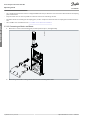
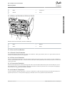
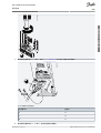
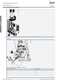
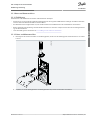
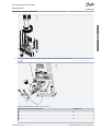
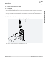
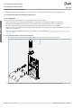
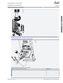
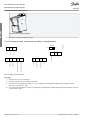
3.2.3.2 Connecting to Mains and Motor
Mount the 2 screws in the mounting plate, slide the plate into place, and tighten fully.
-DC+DC
BR- BR+ U
V
W
99
M A I N S
95
RELA
Y 1 RELA
Y 2
- L
C +
e30ba261.10
Mount the ground cables to the ground terminal before mounting other cables.
AQ32174876762701-000101 / 130R062712 | Danfoss A/S © | 2019.12
Installation
VLT® Compressor Drive CDS 803
Operating Guide
American English

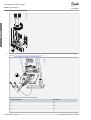
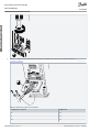
3.
e30ba262.10
M
I N S
+DC
BR-
BR+
U
V
W
RELA Y 1 RELA Y 2
95
Connect the compressor to terminals U, V, and W, and then tighten the screws according to the torques described in 1.3.2.1
Electrical Installation in General.
MO T OR
MO
T
OR
U
V
W
99
e30bt302.12
Table 10: Connection of Compressor to Terminals
Drive terminals
Compressor
U
T1
V
T2
W
T3
AQ32174876762701-000101 / 130R0627 | 13Danfoss A/S © 2019.12
Installation
VLT® Compressor Drive CDS 803
Operating Guide
American English

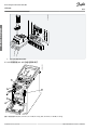
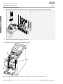
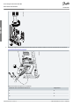
4.
5.
Connect the mains supply to terminals L1, L2, and L3, and then tighten the screws according to the torques.
e30ba263.10
95
M
A
INS
+DC
BR-
BR+
U
V
W
91
92
93
L1
L2
L3
RELA
Y 1 RELA
Y 2
Tighten support bracket on mains wires.
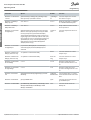
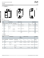
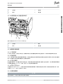
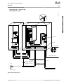
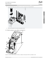
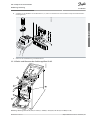
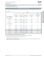
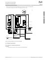
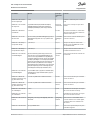
3.2.3.3 Relays and Terminals on Enclosure Sizes H3–H5
e30bb634.10
1
2
2
3
4
M
ot
or
U
V
W
-DC
+DC
M
AINS
Illustration 3: Enclosure Sizes H3–H5, IP20, 200–240 V, 6.0–10 kW (8.0–15 hp), IP20, 380–480 V, 6.0–22 kW (8.0–30 hp)
AQ32174876762701-000101 / 130R062714 | Danfoss A/S © | 2019.12
Installation
VLT® Compressor Drive CDS 803
Operating Guide
American English

1
Mains
2
Ground
3
Compressor
4
Relays
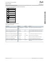
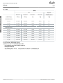
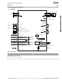
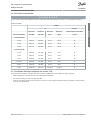
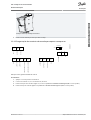
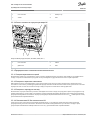
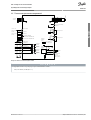
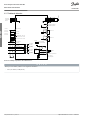
3.2.3.4 Relays and Terminals on Enclosure Size H6
1
95
99
L1 91 / L2 92 / L3 93
U 96 /
V 97 /
W 98
03 02 01
06 05 04
2
3
4
e30bb762.11
Illustration 4: Enclosure Size H6, IP20, 380–480 V, 30 kW (40 hp)
1
Mains
2
Motor
3
Ground
4
Relays
3.2.4 Fuses and Circuit Breakers
3.2.4.1 Branch Circuit Protection
To prevent re hazards, protect the branch circuits in an installation - switch gear, machines, and so on - against short circuits and
overcurrent. Follow national and local regulations.
3.2.4.2 Short-circuit Protection
Danfoss recommends using the fuses and circuit breakers listed in this chapter to protect service personnel or other equipment in
case of an internal failure in the unit or a short circuit on the DC link. The drive provides full short-circuit protection in case of a short
circuit on the motor.
3.2.4.3 Overcurrent Protection
Provide overload protection to avoid overheating of the cables in the installation. Overcurrent protection must always be carried
out according to local and national regulations. Design circuit breakers and fuses for protection in a circuit capable of supplying a
maximum of 100000 A
rms
(symmetrical), 480 V maximum.
3.2.4.4 UL/Non-UL Compliance
To ensure compliance with UL or IEC 61800-5-1, use the circuit breakers or fuses listed in this chapter. Circuit breakers must be de-
signed for protection in a circuit capable of supplying a maximum of 10000 A
rms
(symmetrical), 480 V maximum.
AQ32174876762701-000101 / 130R0627 | 15Danfoss A/S © 2019.12
Installation
VLT® Compressor Drive CDS 803
Operating Guide
American English

•
•
•
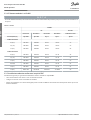
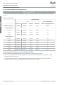
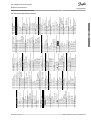
3.2.4.5 Recommendation of Fuses
N O T I C E
If malfunction occurs, failure to follow the protection recommendation may result in damage to the drive.
Table 11: Fuses
Fuse
UL
Non-UL
Bussmann
Bussmann
Bussmann
Bussmann
Maximum fuse
Power [kW (hp)]
Type RK5
Type RK1
Type J
Type T
Type G
3x200–240 V IP20
6.0 (8.0)
FRS-R-50
KTN-R50
JKS-50
JJN-50
50
7.5 (10)
FRS-R-50
KTN-R50
JKS-50
JJN-50
50
10 (15)
FRS-R-80
KTN-R80
JKS-80
JJN-80
65
3x380–480 V IP20
6.0 (8.0)
FRS-R-25
KTS-R25
JKS-25
JJS-25
25
7.5 (10)
FRS-R-25
KTS-R25
JKS-25
JJS-25
25
10 (15)
FRS-R-50
KTS-R50
JKS-50
JJS-50
50
18.5 (25)
FRS-R-80
KTS-R80
JKS-80
JJS-80
63
22 (30)
FRS-R-80
KTS-R80
JKS-80
JJS-80
63
30 (40)
FRS-R-125
KTS-R125
JKS-R125
JJS-R125
80
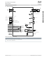
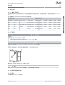
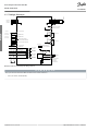
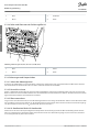
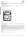
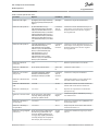
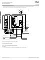
3.2.5 EMC-correct Electrical Installation
General points to be observed to ensure EMC-correct electrical installation:
Use only shielded/armored motor cables and shielded/armored control cables.
Ground the shield at both ends.
Avoid installation with twisted shield ends (pigtails), because it reduces the shielding eect at high frequencies. Use the cable
clamps provided.
AQ32174876762701-000101 / 130R062716 | Danfoss A/S © | 2019.12
Installation
VLT® Compressor Drive CDS 803
Operating Guide
American English

•
•
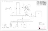
Ensure the same potential between the drive and the ground potential of PLC.
Use star washers and galvanically conductive installation plates.
B
a
c
k
OK
Com.
On
Warn.
Alarm
Hand
On
Reset
Auto
On
Menu
Status Quick
Menu
Main
Menu
L1
L2
L3
PE
Minimum 16 mm
2
equalizing cable
Control cables
All cable entries in
one side of panel
Grounding rail
Cable insula-
tion stripped
Output con-
tactor
Motor cable
Motor, 3 phases and
PLC
Panel
Mains-supply
Minimum 200 mm (7.87 in)
between control
cable, mains cable
and between mains
motor cable
PLC
protective earth
Reinforced protective earth
e30bb761.12
(6 AWG)
Illustration 5: EMC-correct Electrical Installation
AQ32174876762701-000101 / 130R0627 | 17Danfoss A/S © 2019.12
Installation
VLT® Compressor Drive CDS 803
Operating Guide
American English

1.
2.
1.
2.
3.
4.
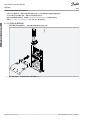
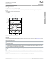
3.2.6 Control Terminals
3.2.6.1 Accessing the Control Terminals
Procedure
To activate the snap, place a screwdriver behind the terminal cover.
e30bb622.11
Illustration 6: Removing the Terminal Cover
Tilt the screwdriver outwards to open the cover.
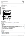
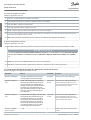
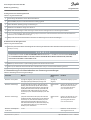
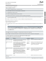
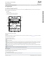
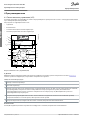
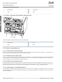
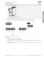
3.2.6.2 Setting the Control Terminals to Run the Compressor
e30bb625.11
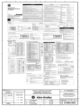
12 20 55
20
27
29 42 45
55
50 53 54
GND
GND
DIGI IN/OUT
DIGI IN/OUT
61
68
69
N
P
COMM. GND
+24 V
DIGI IN
DIGI IN
10 V/20 mA IN
10 V/20 mA IN
0/4-20m A A OUT/DIG OUT
0/4-20 mA A OUT/DIG OUT
10 V OUT
BUS TER.
OFF
ON
Illustration 7: Overview of the Control Terminals
Procedure
Apply a start signal on terminal 18.
Connect terminals 12, 27, and terminal 53, 54, or 55.
Set the functions of digital inputs 18, 19, and 27 in parameter 5-00 Digital Input Mode (PNP is default value).
Set the function of digital input 29 in parameter 5-03 Digital Input 29 Mode (PNP is default value).
AQ32174876762701-000101 / 130R062718 | Danfoss A/S © | 2019.12
Installation
VLT® Compressor Drive CDS 803
Operating Guide
American English
A página está carregando...
A página está carregando...
A página está carregando...
A página está carregando...
A página está carregando...
A página está carregando...
A página está carregando...
A página está carregando...
A página está carregando...
A página está carregando...
A página está carregando...
A página está carregando...
A página está carregando...
A página está carregando...
A página está carregando...
A página está carregando...
A página está carregando...
A página está carregando...
A página está carregando...
A página está carregando...
A página está carregando...
A página está carregando...
A página está carregando...
A página está carregando...
A página está carregando...
A página está carregando...
A página está carregando...
A página está carregando...
A página está carregando...
A página está carregando...
A página está carregando...
A página está carregando...
A página está carregando...
A página está carregando...
A página está carregando...
A página está carregando...
A página está carregando...
A página está carregando...
A página está carregando...
A página está carregando...
A página está carregando...
A página está carregando...
A página está carregando...
A página está carregando...
A página está carregando...
A página está carregando...
A página está carregando...
A página está carregando...
A página está carregando...
A página está carregando...
A página está carregando...
A página está carregando...
A página está carregando...
A página está carregando...
A página está carregando...
A página está carregando...
A página está carregando...
A página está carregando...
A página está carregando...
A página está carregando...
A página está carregando...
A página está carregando...
A página está carregando...
A página está carregando...
A página está carregando...
A página está carregando...
A página está carregando...
A página está carregando...
A página está carregando...
A página está carregando...
A página está carregando...
A página está carregando...
A página está carregando...
A página está carregando...
A página está carregando...
A página está carregando...
A página está carregando...
A página está carregando...
A página está carregando...
A página está carregando...
A página está carregando...
A página está carregando...
A página está carregando...
A página está carregando...
A página está carregando...
A página está carregando...
A página está carregando...
A página está carregando...
A página está carregando...
A página está carregando...
A página está carregando...
A página está carregando...
A página está carregando...
A página está carregando...
A página está carregando...
A página está carregando...
A página está carregando...
A página está carregando...
A página está carregando...
A página está carregando...
A página está carregando...
A página está carregando...
A página está carregando...
A página está carregando...
A página está carregando...
A página está carregando...
A página está carregando...
A página está carregando...
A página está carregando...
A página está carregando...
A página está carregando...
A página está carregando...
A página está carregando...
A página está carregando...
A página está carregando...
A página está carregando...
A página está carregando...
A página está carregando...
A página está carregando...
A página está carregando...
A página está carregando...
A página está carregando...
A página está carregando...
A página está carregando...
A página está carregando...
A página está carregando...
A página está carregando...
A página está carregando...
A página está carregando...
A página está carregando...
A página está carregando...
A página está carregando...
A página está carregando...
A página está carregando...
A página está carregando...
A página está carregando...
A página está carregando...
A página está carregando...
A página está carregando...
A página está carregando...
A página está carregando...
A página está carregando...
A página está carregando...
A página está carregando...
A página está carregando...
A página está carregando...
A página está carregando...
A página está carregando...
A página está carregando...
A página está carregando...
A página está carregando...
A página está carregando...
A página está carregando...
A página está carregando...
A página está carregando...
A página está carregando...
A página está carregando...
A página está carregando...
A página está carregando...
A página está carregando...
A página está carregando...
A página está carregando...
A página está carregando...
A página está carregando...
A página está carregando...
A página está carregando...
A página está carregando...
A página está carregando...
A página está carregando...
A página está carregando...
A página está carregando...
A página está carregando...
A página está carregando...
A página está carregando...
A página está carregando...
A página está carregando...
A página está carregando...
A página está carregando...
A página está carregando...
A página está carregando...
A página está carregando...
A página está carregando...
A página está carregando...
A página está carregando...
A página está carregando...
A página está carregando...
A página está carregando...
A página está carregando...
A página está carregando...
A página está carregando...
A página está carregando...
A página está carregando...
A página está carregando...
A página está carregando...
A página está carregando...
A página está carregando...
A página está carregando...
A página está carregando...
A página está carregando...
A página está carregando...
A página está carregando...
A página está carregando...
A página está carregando...
A página está carregando...
A página está carregando...
A página está carregando...
A página está carregando...
A página está carregando...
A página está carregando...
A página está carregando...
A página está carregando...
A página está carregando...
A página está carregando...
A página está carregando...
A página está carregando...
A página está carregando...
A página está carregando...
A página está carregando...
A página está carregando...
A página está carregando...
A página está carregando...
A página está carregando...
A página está carregando...
A página está carregando...
A página está carregando...
A página está carregando...
A página está carregando...
A página está carregando...
A página está carregando...
A página está carregando...
A página está carregando...
A página está carregando...
A página está carregando...
A página está carregando...
A página está carregando...
A página está carregando...
A página está carregando...
A página está carregando...
A página está carregando...
A página está carregando...
A página está carregando...
A página está carregando...
A página está carregando...
A página está carregando...
A página está carregando...
A página está carregando...
A página está carregando...
A página está carregando...
A página está carregando...
A página está carregando...
A página está carregando...
A página está carregando...
A página está carregando...
A página está carregando...
A página está carregando...
A página está carregando...
A página está carregando...
A página está carregando...
A página está carregando...
A página está carregando...
A página está carregando...
A página está carregando...
A página está carregando...
A página está carregando...
A página está carregando...
A página está carregando...
A página está carregando...
A página está carregando...
A página está carregando...
A página está carregando...
A página está carregando...
A página está carregando...
A página está carregando...
A página está carregando...
A página está carregando...
A página está carregando...
A página está carregando...
A página está carregando...
A página está carregando...
A página está carregando...
A página está carregando...
A página está carregando...
A página está carregando...
A página está carregando...
A página está carregando...
A página está carregando...
A página está carregando...
A página está carregando...
A página está carregando...
A página está carregando...
A página está carregando...
A página está carregando...
A página está carregando...
A página está carregando...
A página está carregando...
A página está carregando...
A página está carregando...
-
 1
1
-
 2
2
-
 3
3
-
 4
4
-
 5
5
-
 6
6
-
 7
7
-
 8
8
-
 9
9
-
 10
10
-
 11
11
-
 12
12
-
 13
13
-
 14
14
-
 15
15
-
 16
16
-
 17
17
-
 18
18
-
 19
19
-
 20
20
-
 21
21
-
 22
22
-
 23
23
-
 24
24
-
 25
25
-
 26
26
-
 27
27
-
 28
28
-
 29
29
-
 30
30
-
 31
31
-
 32
32
-
 33
33
-
 34
34
-
 35
35
-
 36
36
-
 37
37
-
 38
38
-
 39
39
-
 40
40
-
 41
41
-
 42
42
-
 43
43
-
 44
44
-
 45
45
-
 46
46
-
 47
47
-
 48
48
-
 49
49
-
 50
50
-
 51
51
-
 52
52
-
 53
53
-
 54
54
-
 55
55
-
 56
56
-
 57
57
-
 58
58
-
 59
59
-
 60
60
-
 61
61
-
 62
62
-
 63
63
-
 64
64
-
 65
65
-
 66
66
-
 67
67
-
 68
68
-
 69
69
-
 70
70
-
 71
71
-
 72
72
-
 73
73
-
 74
74
-
 75
75
-
 76
76
-
 77
77
-
 78
78
-
 79
79
-
 80
80
-
 81
81
-
 82
82
-
 83
83
-
 84
84
-
 85
85
-
 86
86
-
 87
87
-
 88
88
-
 89
89
-
 90
90
-
 91
91
-
 92
92
-
 93
93
-
 94
94
-
 95
95
-
 96
96
-
 97
97
-
 98
98
-
 99
99
-
 100
100
-
 101
101
-
 102
102
-
 103
103
-
 104
104
-
 105
105
-
 106
106
-
 107
107
-
 108
108
-
 109
109
-
 110
110
-
 111
111
-
 112
112
-
 113
113
-
 114
114
-
 115
115
-
 116
116
-
 117
117
-
 118
118
-
 119
119
-
 120
120
-
 121
121
-
 122
122
-
 123
123
-
 124
124
-
 125
125
-
 126
126
-
 127
127
-
 128
128
-
 129
129
-
 130
130
-
 131
131
-
 132
132
-
 133
133
-
 134
134
-
 135
135
-
 136
136
-
 137
137
-
 138
138
-
 139
139
-
 140
140
-
 141
141
-
 142
142
-
 143
143
-
 144
144
-
 145
145
-
 146
146
-
 147
147
-
 148
148
-
 149
149
-
 150
150
-
 151
151
-
 152
152
-
 153
153
-
 154
154
-
 155
155
-
 156
156
-
 157
157
-
 158
158
-
 159
159
-
 160
160
-
 161
161
-
 162
162
-
 163
163
-
 164
164
-
 165
165
-
 166
166
-
 167
167
-
 168
168
-
 169
169
-
 170
170
-
 171
171
-
 172
172
-
 173
173
-
 174
174
-
 175
175
-
 176
176
-
 177
177
-
 178
178
-
 179
179
-
 180
180
-
 181
181
-
 182
182
-
 183
183
-
 184
184
-
 185
185
-
 186
186
-
 187
187
-
 188
188
-
 189
189
-
 190
190
-
 191
191
-
 192
192
-
 193
193
-
 194
194
-
 195
195
-
 196
196
-
 197
197
-
 198
198
-
 199
199
-
 200
200
-
 201
201
-
 202
202
-
 203
203
-
 204
204
-
 205
205
-
 206
206
-
 207
207
-
 208
208
-
 209
209
-
 210
210
-
 211
211
-
 212
212
-
 213
213
-
 214
214
-
 215
215
-
 216
216
-
 217
217
-
 218
218
-
 219
219
-
 220
220
-
 221
221
-
 222
222
-
 223
223
-
 224
224
-
 225
225
-
 226
226
-
 227
227
-
 228
228
-
 229
229
-
 230
230
-
 231
231
-
 232
232
-
 233
233
-
 234
234
-
 235
235
-
 236
236
-
 237
237
-
 238
238
-
 239
239
-
 240
240
-
 241
241
-
 242
242
-
 243
243
-
 244
244
-
 245
245
-
 246
246
-
 247
247
-
 248
248
-
 249
249
-
 250
250
-
 251
251
-
 252
252
-
 253
253
-
 254
254
-
 255
255
-
 256
256
-
 257
257
-
 258
258
-
 259
259
-
 260
260
-
 261
261
-
 262
262
-
 263
263
-
 264
264
-
 265
265
-
 266
266
-
 267
267
-
 268
268
-
 269
269
-
 270
270
-
 271
271
-
 272
272
-
 273
273
-
 274
274
-
 275
275
-
 276
276
-
 277
277
-
 278
278
-
 279
279
-
 280
280
-
 281
281
-
 282
282
-
 283
283
-
 284
284
-
 285
285
-
 286
286
-
 287
287
-
 288
288
-
 289
289
-
 290
290
-
 291
291
-
 292
292
-
 293
293
-
 294
294
-
 295
295
-
 296
296
-
 297
297
-
 298
298
-
 299
299
-
 300
300
-
 301
301
-
 302
302
-
 303
303
-
 304
304
-
 305
305
-
 306
306
-
 307
307
-
 308
308
-
 309
309
-
 310
310
-
 311
311
-
 312
312
-
 313
313
-
 314
314
-
 315
315
-
 316
316
-
 317
317


Danfoss VLT Compressor Drive CDS 803 Guia de usuario
- Tipo
- Guia de usuario
em outras línguas
Artigos relacionados
-
Danfoss VLT OneGearDrive Guia de instalação
-
-
Danfoss VLT Micro Drive FC 51 M4 Guia de usuario
-
-
Danfoss PR-SC4K Guia de instalação
-
-
-
Danfoss 120H1426 Guia de instalação
-
Danfoss EKE 400 Guia de instalação
-
Outros documentos
-
Omron VS MINI J7 Manual do proprietário
-
 Rockwell Automation C09 Series Guia de instalação
-
EINHELL TC-LD 50 Manual do usuário
-
Televes RF Amplifier Ficha de dados
-
EINHELL TC-LD 25 Manual do usuário
-
 Allen-Bradley 22HIM-QR001 Guia de referência
-
 ElectriChef 24″ 220V Informação do produto
-
 Rockwell Automation Allen-Bradley 900-TC32 Manual do usuário
-
-
Hager EH010 Manual do usuário


