
UNDERCOUNTER ICE MACHINE
INSTALLATION GUIDE
SPECIFICATIONS, INSTALLATION, AND MORE

UNDERCOUNTER ICE MACHINE
Important Note
To ensure this product is installed and operated as safely
and efciently as possible, take note of the following types
of highlighted information throughout this guide:
IMPORTANT NOTE highlights information that is especially
important.
CAUTION indicates a situation where minor injury or product
damage may occur if instructions are not followed.
WARNING states a hazard that may cause serious injury or
death if precautions are not followed.
IMPORTANT NOTE: Throughout this guide, dimensions in
parentheses are millimeters unless otherwise specied.
IMPORTANT NOTE: Save these instructions for the local
electrical inspector.
2
|
Sub-Zero Customer Care 800.222.7820
Contents
3 Undercounter Ice Machine
4 Opening Dimensions
5 Electrical
6 Plumbing
7 Installation
10 Custom Panel
11 Completion
Features and specications are subject to change at any
time without notice. Visit subzero.com/specs for the most
up-to-date information.

subzero.com
|
3
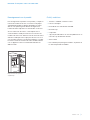
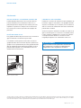
Product Information
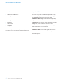
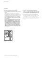
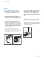
Important product information, including the model and
serial number, are listed on the product rating plate. The
rating plate is located in the upper left corner of the ice
storage bin, on the back of the unit. Refer to the illustration
below.
If service is necessary, contact Sub-Zero Factory Certied
Service with the model and serial number. For the name
of the nearest Sub-Zero Factory Certied Service or for
questions regarding the installation, visit the contact & sup-
port section of our website, subzero.com, or call Sub-Zero
customer care at 800-222-7820.
UNDERCOUNTER ICE MACHINE
Tools and Materials
• Screwdrivers—standard, Phillips and Torx.
• Power drill.
• Standard socket and wrench set.
• 2' level.
• Tubing cutter.
• 3'
(.9 m) of
1
/4" OD copper, braided stainless steel or
PEX tubing.
• Saddle valve.
• Material to protect home, ooring and cabinetry during
installation.
Rating plate location
RATING
PLATE

4
|
Sub-Zero Customer Care 800.222.7820
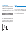
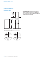
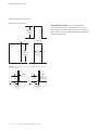
SITE PREPARATION
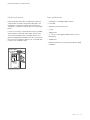
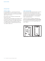
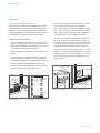
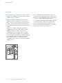
Opening Dimensions
ICE MACHINE
IMPORTANT NOTE:
It is recommended that the electrical
and water supply be placed in an adjacent cabinet. If they
are placed within the opening, additional cabinet depth may
be required.
15
1
/4"
(387)
OPENING
WIDTH
34
1
/
2
"
(876)
OPENING
HEIGHT
TOP VIEW
SIDE VIEW FRONT VIEW
NOTE: 3
1
/2" (89) finished returns will be visible and should be finished to match cabinetry
.
3
/4" (19)
TYPICAL
FRAMED
CABINETRY
15
1
/4"
(387)
FILLER
3
1
/2" (89)
FINISHED
RETURN
FRAMELESS
CABINETRY
15
1
/4"
(387)
3
/4" (19)
TYPICAL
3
1
/2" (89)
FINISHED
RETURN
24" (610)
OPENING
DEPTH

subzero.com
|
5
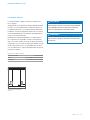
SITE PREPARATION
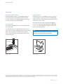
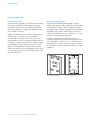
Electrical Requirements
Installation must comply with all applicable electrical codes.
Although it can be located anywhere on the back wall, it
is recommended that the electrical supply be placed in an
adjacent cabinet or in the lower right of the opening. Refer
to the illustration below. A separate circuit servicing only this
appliance is required.
Model UC-15I(P)O is designed and safe for use in outdoor
applications. When installed outdoors, a ground fault circuit
interrupter (GFCI) is required to reduce the risk of electrical
shock. A GFCI is not recommended for use with the indoor
model and may cause interruption of operation.
ELECTRICAL REQUIREMENTS
Electrical Supply 115 VAC, 60 Hz
Service 15 amp dedicated circuit
Receptacle 3-prong grounding-type
E
E
E
Electrical supply location
CAUTION
The outlet must be checked by a qualied electrician to
be sure that it is wired with the correct polarity. Verify
that the outlet is properly grounded.
WARNING
Do not use an extension cord, two-prong adapter or
remove the power cord ground prong.

6
|
Sub-Zero Customer Care 800.222.7820
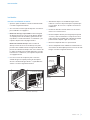
SITE PREPARATION
Preparation
CAUTION
Before moving the unit into position, secure the door
closed and protect any nished ooring.
Uncrate the unit and inspect for damage. Remove the wood
base and discard shipping bolts and brackets. Remove and
recycle packing materials. Do not discard the kickplate and
hardware.
Use an appliance dolly to move the unit near the opening.
If the unit has been on its back or side, it must stand upright
for a minimum of 24 hours before connecting power.
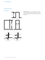
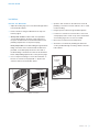
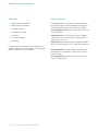
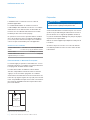
Plumbing Requirements
Installation must comply with all applicable plumbing codes.
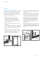
The water supply line should be located as shown in the
illustration below. The water supply line should be con-
nected to the house supply with an easily accessible shut-
off valve. Do not use self-piercing valves.
A reverse osmosis system can be used provided there is
constant water pressure of 20–80 psi
(1.4–5.5 bar) supplied to
the unit at all times. A copper line is not recommended for
this application.
PLUMBING REQUIREMENTS
Water Supply Line
1
/4" OD copper, braided stain-
less steel or PEX tubing
Water Pressure 20–80 psi
(1.4–5.5 bar)
Excess Water Line for Connection 36" (914)
ICE MACHINE DRAIN
The ice machine can be ordered with or without a drain
pump. Models without a pump will drain water by gravity.
A drain must be installed.
The drain and inlet water tubes must be plumbed before
connecting to the ice machine. For the gravity drain, hori-
zontal drain lines must have a
1
/4" (6) per 12" (305) fall. An
air gap will likely be required between the unit and drain.
A stand pipe with a trap below is acceptable for the drain.
34
1
/2" (876)
ROUGH
OPENING
HEIGHT
33
5
/8" (854)
MINIMUM
HEIGHT
REQUIRED
15
1
/
4
"
min (387)
ROUGH
OPENING WIDTH
24" (610)
ROUGH
OPENING
DEPTH
POSITION OUTLET
WITH GROUNDING
PRONG ON RIGHT
LOCATION OF
WATER LINE
8"
(203)
1
/2"
(
13
)
TOP VIEW
FRONT VIEW
4"
(
102
)
LOCATE
ELECTRICAL
WITHIN
SHADED AREA
Water supply location

subzero.com
|
7
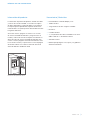
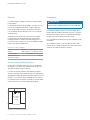
Installation
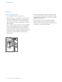
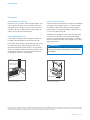
INSTALL ICE MACHINE
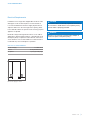
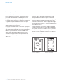
1 Adjust the leveling legs close to the desired height. Refer
to the illustration below.
2 Reverse the door swing if needed. Refer to steps out-
lined on page 9.
3 Gravity drain model: Install the drain hose provided,
onto the drain tting on the back of unit and route to
the open site drain. Refer to the illustration below and
plumbing requirements on the previous page.
Drain pump model: Route drain tubing through the drain
tting on the back of the unit and install the drain hose
provided, on the drain pump. Route the other end of
the drain tubing to the drain site. Refer to the illustration
below and plumbing requirements on the previous page.
4 Use a compression tting to connect the water inlet on
back of ice machine to the prepared
1
/4" (6) OD cold
water line. Refer to the illustration below.
5 Open the shut-off valve on the water line. Check all
plumbing connections for leaks. Failure to do so could
result in ooding.
6 Plug the power cord into the grounded receptacle.
7 Level the ice machine to assure the door closes and
seals properly. Place a level on top of the unit and turn
each leveling leg to raise or lower as needed.
8 Move the ice machine into its nal position.
9 Anchor the ice machine by installing two at head
screws provided through each hinge. Refer to the illus-
tration below.
INSTALLATION
ANCHORING
SCREWS
Anchoring
LEVELING
LEG
WATER INLET
DRAIN FITTING
Leveling
Drain connection

8
|
Sub-Zero Customer Care 800.222.7820
INSTALLATION
Installation
VERIFY ICE PRODUCTION
1 Press ‘POWER’ to turn the ice machine on.
2 Add one gallon (3.8 L) of cold water to the ice bin. Verify
the water completely drains from the ice bin and there
are no leaks. If the water has not drained within 60 sec-
onds, there may be a kink in the drain tube or incorrect
drain installation.
3 Press ‘CLEAN’. Wait three minutes until the CLEAN light
ashes, then add 1 tablespoon
(15 ml) of undiluted ice
machine sanitizer directly into the spray area. Refer to
the illustration below. Use only the sanitizer made for the
Sub-Zero ice machine available at subzerowolfstore.com.
For questions, contact Sub-Zero customer care at
800-222-7820.
Water shutters location
WATER
SHUTTERS
4 A 10-minute sanitizing cycle begins, followed by eight
rinse cycles. When the process is complete, the CLEAN
light will no longer be illuminated. The entire cycle takes
approximately 30 minutes.
5 At initial start-up, the ice machine will need approxi-
mately 30 minutes to freeze ice cubes and up to ve
minutes to harvest. Verify completion of the rst cycle ice
production to conrm proper installation.

subzero.com
|
9
Installation
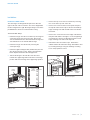
REVERSE DOOR SWING
The door hinges are designed to be placed on either the
right or left side of the ice machine. The unit is shipped with
the door hinged on the right. Moving the hinges to the left in
pre-drilled holes, allows for a left-hand door swing.
To reverse door swing:
1 Detach the hinges from the ice machine by removing two
screws per hinge, then remove the door. Remove the
shim located between the cabinet and bottom hinge, this
shim will transfer to the left side bottom hinge.
2 Detach the hinges from the door by removing two
screws per hinge.
3 Detach the right-hand upper trim (shaded area) from the
door by removing two screws. Refer to the illustration
below. Replace it with the left-hand upper trim.
4 Transfer the hinges to the left side of the door and
reinstall. The upper hinge will now be in the lower hinge
position and the lower hinge in the upper hinge position.
5 Remove the top cover of the ice machine by removing
two screws at the top rear of the unit.
6 Remove four screws from the front top rail, then pivot
the top rail end for end to expose the two left-hand top
hinge mounting holes and reinstall. Refer to the illustra-
tion below.
7 Remove two screws from the lower edge of the bottom
trim plate and slide it to the right to cover the right hinge
mounting holes. Refer to the illustration below. The left
hinge mounting holes will now be exposed.
8 Reinstall the shim removed in step 1, between the
cabinet and the left side bottom hinge. Reinstall the door
by mounting the hinges using the left hinge mounting
holes. Verify operation of door.
INSTALLATION
HINGE
SCREWS
UPPER
TRIM (RH)
HINGE
HINGE
Remove door
Detach hinges and trim
TOP RAIL
SCREWS
TRIM PLATE
SCREWS
Front top rail
Bottom trim plate

10
|
Sub-Zero Customer Care 800.222.7820
INSTALLATION
Custom Panel
OVERLAY PANEL
For overlay applications, a custom door panel must be
installed. Panel size is critical for a proper t. To verify panel
requirements and dimensions, refer to the Sub-Zero design
guide at subzero.com/specs.
Finish all sides of the custom panel. They will be visible
when the door is open.
A D-style handle is recommended. The door handle must be
located near the edge of the panel opposite the hinge, cen-
tered top to bottom. Stainless steel tubular and pro handles
are avail able through an authorized Sub-Zero dealer. For
local dealer information, visit the nd a showroom section
of our website, subzero.com.
PANEL INSTALLATION
Remove the handle side bracket attached to the front of the
door. Place the custom door panel face down on a pro-
tected work surface. Place the template on the back of the
door panel, then mark and drill holes. Secure the mounting
bracket to the panel with the #8 x
1
/2" screws provided.
Refer to the illustration below.
Install the door panel by engaging the tabbed bracket to
the door. Once the door panel is in place, use the remaining
#8 x
1
/2" screws to secure the panel to the upper and lower
mounting brackets. Once secure, install the hinge covers.
Refer to page 11.
UPPER
BRACKET
LOWER
BRACKET
Template position
Mounting brackets

subzero.com
|
11
INSTALLATION
Completion
KICKPLATE INSTALLATION
Install the kickplate using two screws provided. Refer to
the illustration below. The kickplate must be removable
for service. The oor cannot interfere with removal. Do not
cover the louvered section of the kickplate.
90° DOOR STOP
Door stop pins provided with the ice machine will limit the
door swing to 90°.
To install, open the door to approximately 80°. Insert one
stop pin into the top door hinge (pin enters from the bottom)
and the other stop pin into the bottom door hinge (pin
enters from the top). Refer to the illustration below. Check
for proper operation.
HINGE COVERS
Install hinge covers once installation of the ice machine is
complete and door stop pins have been installed (if appli-
cable). The knock-out in the hinge cover must be removed
if the 90° door stop is used.
Verify hinges are free of dirt or grease before applying
covers. To install, remove paper backing and apply hinge
covers to each hinge. Attach the magnetic center covers.
Refer to the illustration below.
WARNING
Follow all city and state laws when storing, recycling or
discarding unused refrigerators and freezers.
DOOR STOP PIN
90° door stop
KNOCK-OUT
Hinge covers
Sub-Zero, Sub-Zero & Design, Sub-Zero & Snowake Design, Dual Refrigeration, The Living Kitchen, Great American Kitchens The Fine Art of Kitchen Design, Wolf, Wolf &
Design, Wolf Gourmet, W & Design, red colored knobs, Cove, and Cove & Design are registered trademarks and service marks of Sub-Zero Group, Inc. and its subsidiaries.
All other trademarks are property of their respective owners in the United States and other countries.

2
|
Atención al cliente de Sub-Zero 800.222.7820
MÁQUINA DE HIELO EMPOTRADA
Aviso importante
Para garantizar que este producto se instale y opere de
la forma más segura y eciente posible, tome nota de los
siguientes tipos de información resaltada en esta guía:
AVISO IMPORTANTE señala la información que es especial-
mente importante.
PRECAUCIÓN indica una situación en la que se pueden
sufrir heridas leves o provocar daños al producto si no se
siguen las instrucciones.
ADVERTENCIA indica peligro de que se produzcan heridas
graves o incluso la muerte si no se siguen las precauciones.
AVISO IMPORTANTE: en toda esta guía, las dimensiones
entre paréntesis son milímetros, a menos que se especi-
que lo contrario.
AVISO IMPORTANTE: guarde estas instrucciones para el
inspector eléctrico local.
Contenido
3 Máquina de hielo empotrada
4 Dimensiones de la abertura
5 Instalación eléctrica
6 Instalación de plomería
7 Instalación
10 Panel personalizado
11 Finalización
Las características y especicaciones están sujetas a
cambios sin previo aviso. Visite subzero.com/specs para
obtener la información más actualizada.

subzero.com
|
3
Información del producto
La información importante del producto, incluido el modelo
y número de serie de la unidad, se encuentra en la placa
de datos del producto. La placa de datos se encuentra en
la esquina superior izquierda del recipiente de almacena-
miento de hielo, en la parte posterior de la unidad. Consulte
la siguiente ilustración.
Si necesita servicio, póngase en contacto con el centro
de servicio autorizado de Sub-Zero y tenga a la mano el
modelo y número de serie de la máquina. Para obtener los
datos del centro de servicio autorizado de Sub-Zero más
cercano o si tiene preguntas acerca de la instalación, visite
la sección de contacto y soporte técnico en nuestra página
de Internet subzero.com o llame a la línea de atención al
cliente de Sub-Zero al 800-222-7820.
MÁQUINA DE HIELO EMPOTRADA
Herramientas | Materiales
• Destornilladores: estándar, Phillips y Torx.
• Taladro eléctrico.
• Juego de llaves de cubo e inglesas estándar.
• Nivel de 2'.
• Cortador de tubos.
• 3'
(.9 m) de tubería de cobre, trenzada de acero inoxi-
dable o PEX de
1
/4" de diámetro exterior.
• Válvula de asiento.
• Material para proteger la casa, el piso y los gabinetes
durante la instalación.
Ubicación de la placa de datos
PLACA DE
DATOS

4
|
Atención al cliente de Sub-Zero 800.222.7820
PREPARACIÓN DEL SITIO
Dimensiones de abertura
MÁQUINA DE HIELO
AVISO IMPORTANTE:
Se recomienda que el suministro
eléctrico y de agua se encuentren en un gabinete adya-
cente. Si se encuentra dentro de la abertura, posiblemente
el gabinete deba ser más profundo.
15
1
/4"
(387)
ANCHURA DE
ABERTURA
34
1
/2"
(876)
ALTURA DE
LA ABERTURA
VISTA SUPERIOR
VISTA LATERAL VISTA FRONTAL
NOTA: Los tubos de retorno de 3
1
/2" (89) con acabados se podrán ver y se deben
terminar para que se ajusten a los gabinetes.
24"
(610)
PROFUNDIDAD
DE LA
ABERTURA
TÍPICO
DE
3
/4" (19)
GABINETE CON
MARCO
15
1
/4"
(387)
RELLENO
TUBO DE
RETORNO DE
3
1
/2" (89) CON
ACABADOS
TUBO DE
RETORNO DE
3
1
/2" (89) CON
ACABADOS
GABINETE SIN
MARCO
15
1
/4"
(387)
TÍPICO
DE
3
/4" (19)

subzero.com
|
5
PREPARACIÓN DEL SITIO
Instalación eléctrica
La instalación debe cumplir con todos los códigos eléc-
tricos vigentes.
Aunque puede estar ubicado en cualquier lugar de la pared
posterior, se recomienda instalar el suministro eléctrico en
un gabinete adyacente o en la esquina inferior derecha de
la abertura. Consulte la siguiente ilustración. Se necesita un
circuito independiente que le suministre electricidad única-
mente a este electrodoméstico.
El Modelo UC-15I(P)O está diseñado y es seguro para su
uso en aplicaciones al aire libre. Cuando se instala al aire
libre, es necesario instalar un circuito de fallos de conexión
a tierra (GFCI, por sus siglas en inglés) para reducir el riesgo
de descarga eléctrica. No es recomendable usar un GFCI
con el modelo interior, ya que puede interrumpir el funciona-
miento de la unidad.
REQUISITOS ELÉCTRICOS
Suministro eléctrico 115 V CA, 60 Hz
Servicio Circuito dedicado de 15 amperes
Receptáculo Conexión a tierra de 3 clavijas
E
E
E
Ubicación del suministro
eléctrico
PRECAUCIÓN
Un electricista calicado debe revisar el tomacorriente
para asegurarse de que la conexión se haya realizado
con la polaridad correcta. Verique que el tomaco-
rriente esté debidamente conectado a tierra.
ADVERTENCIA
No use un cable de extensión, adaptador de dos cla-
vijas ni retire la clavija con conexión a tierra del cable
de corriente.

6
|
Atención al cliente de Sub-Zero 800.222.7820
PREPARACIÓN DEL SITIO
Preparación
PRECAUCIÓN
Antes de mover la unidad a su posición, verique que
la puerta esté cerrada y proteja el suelo con acabado.
Desembale la unidad e inspeccione si tiene algún daño.
Retire la base de madera y deseche los pernos y soportes
de transporte. Retire y recicle los materiales de embalaje.
No deseche el zócalo ni las piezas de montaje.
Use una plataforma rodante para mover la unidad cerca de
la abertura.
Si la unidad ha estado o está acostada o de lado, debe
ponerla de pie y dejarla así durante un mínimo de 24 horas
antes de conectarla al suministro eléctrico.
Plomería
La instalación debe cumplir con todos los códigos de plo-
mería vigentes.
La tubería del suministro de agua debe colocarse como se
muestra en la siguiente ilustración. La tubería del sumi-
nistro de agua debe conectarse al suministro doméstico
con una válvula de cierre de fácil acceso. No use válvulas
autoperforantes.
Se puede usar un sistema de ósmosis inversa siempre
y cuando la presión del agua que llegue a la unidad se
mantenga de forma constante entre 20 a 80 psi
(de 1.4 a
5.5bares)
en todo momento. No es recomendable usar tube-
rías de cobre para esta aplicación.
REQUISITOS DE PLOMERÍA
Tuberías de suministro
de agua
Tubería de cobre, trenzada de acero inoxi-
dable o PEX de
1
/4" de diámetro exterior
Presión del agua De 20 a 80 psi
(de 1.4 a 5.5 bares)
Tubería de exceso de
agua para la conexión
36" (914)
DRENAJE DE LA MÁQUINA DE HIELO
Puede ordenar la máquina de hielo con o sin una bomba
de drenaje. Los modelos sin bomba drenarán el agua por
gravedad. Se debe instalar un drenaje.
Los tubos de agua de entrada y drenaje deben instalarse
antes de conectarlos a la máquina de hielo. Para el drenaje por
gravedad, las tuberías de drenaje horizontales deben tener una
caída de
1
/4" (6) cada 12" (305). Es probable que se requiera
un entrehierro entre la máquina y el drenaje. Se puede utilizar
un tubo vertical con un colector abajo para el drenaje.
34
1
/2" (876)
ROUGH
OPENING
HEIGHT
33
5
/8" (854)
MINIMUM
HEIGHT
REQUIRED
15
1
/4"min (387)
ROUGH
OPENING WIDTH
24" (610)
ROUGH
OPENING
DEPTH
POSITION OUTLET
WITH GROUNDING
PRONG ON RIGHT
UBICACIÓN DE
LA LÍNEA
DE AGUA
8"
(203)
1
/2"
(
13
)
VISTA SUPERIOR
FRONT VIEW
4"
(
102
)
LOCATE
ELECTRICAL
WITHIN
SHADED AREA
Ubicación del suministro de agua

subzero.com
|
7
Instalación
INSTALE LA MÁQUINA DE HIELO
1 Ajuste las patas niveladoras cerca de la altura deseada.
Consulte la siguiente ilustración.
2 Si es necesario, invierta el giro de la puerta. Consulte los
pasos indicados en la página 9.
3 Modelo de drenaje por gravedad: Instale la manguera
de drenaje provista en el accesorio de drenaje ubicado
en la parte posterior de la unidad y guíela hacia el dre-
naje abierto. Consulte la ilustración a continuación y los
requisitos de plomería en la página anterior.
Modelo de bomba de drenaje: Guíe los tubos de
drenaje a través del accesorio de drenaje en la parte
posterior de la unidad e instale la manguera de drenaje
provista en la bomba de drenaje. Guíe el otro extremo de
los tubos de drenaje hacia el lugar de drenaje. Consulte
la ilustración a continuación y los requisitos de plomería
en la página anterior.
4 Use un accesorio de compresión para conectar la
entrada de agua en la parte posterior de la máquina
de hielo a la tubería de agua fría de
1
/4" (6) de diámetro
exterior. Consulte la siguiente ilustración.
5 Abra la llave de paso en la tubería de agua. Revise
todas las conexiones de plomería para comprobar que
no haya fugas. Si no lo hace, se puede ocasionar una
inundación.
6 Enchufe el cable de corriente eléctrica en un tomaco-
rriente con conexión a tierra.
7 Nivele la máquina de hielo para asegurar que la puerta
se cierre y selle correctamente. Coloque un nivel en la
parte superior de la unidad y gire cada pata niveladora
para levantarla o bajarla, según sea necesario.
8 Mueva la máquina de hielo a su posición nal.
9 Ancle la máquina de hielo mediante la instalación de los
dos tornillos de cabeza plana provistos a través de cada
bisagra. Consulte la siguiente ilustración.
INSTALACIÓN
TORNILLOS
DE ANCLAJE
Anclaje
PATA
NIVELADORA
ENTRADA DE AGUA
ACCESORIO DE DRENAJE
Nivelación
Conexión de drenaje

8
|
Atención al cliente de Sub-Zero 800.222.7820
INSTALACIÓN
Instalación
VERIFIQUE LA PRODUCCIÓN DE HIELO
1 Presione ‘POWER’ (Potencia) para encender la máquina
de hielo.
2 Agregue un galón (3.8 l) de agua fría al recipiente de
hielo. Verique que el agua se drene completamente del
recipiente de hielo y que no haya fugas. Si el agua no se
ha drenado dentro de 60 segundos, el tubo de drenaje
puede estar doblado o el drenaje puede estar instalado
incorrectamente.
3 Presione ‘CLEAN’ (Limpiar). Espere tres minutos hasta
que la luz CLEAN parpadee, luego, agregue 1 cucha-
rada
(15 ml) de desinfectante para generadores de hielo
sin diluir directamente en la zona de rocío. Consulte la
siguiente ilustración. Solo use un desinfectante elabo-
rado para la
máquina de hielo Sub-Zero disponible en
subzerowolfstore.com. Si tiene alguna pregunta, comu-
níquese con la línea de atención al cliente de Sub-Zero
al 800-222-7820.
Ubicación de los obturadores
de agua
OBTURADORES
DE AGUA
4 Comienza un ciclo de desinfección de 10 minutos,
seguido de ocho ciclos de enjuague. Una vez que el pro-
ceso haya nalizado, la luz CLEAN dejará de estar ilumi-
nada. Todo el ciclo dura aproximadamente 30minutos.
5 En la puesta en marcha inicial, la máquina de hielo
necesitará aproximadamente 30 minutos para congelar
los cubos de hielo y hasta cinco minutos para reco-
gerlos. Verique la nalización de la producción de hielo
del primer ciclo para conrmar que la instalación esté
correcta.

subzero.com
|
9
Instalación
INVIERTA EL GIRO DE LA PUERTA
Las bisagras de la puerta están diseñadas para colocarse
en el lado derecho o izquierdo de la máquina de hielo. La
máquina se envía con la bisagra de la puerta a la derecha.
Si mueve las bisagras a la izquierda en los oricios previa-
mente perforados, podrá girar la puerta a la izquierda.
Para invertir el giro de la puerta:
1 Retire las bisagras de la máquina de hielo sacando dos
tornillos por bisagra, luego quite la puerta. Retire la cuña
ubicada entre el gabinete y la bisagra inferior; esta cuña
se cambiará a la bisagra inferior izquierda.
2 Retire las bisagras de la puerta sacando dos tornillos por
bisagra.
3 Quite el ribete superior derecho (área sombreada) de
la puerta sacando dos tornillos. Consulte la siguiente
ilustración. Reemplácelo con el ribete superior izquierdo.
4 Cambie las bisagras al lado izquierdo de la puerta y
vuelva a instalarlas. Ahora la bisagra superior estará en
la posición de la bisagra inferior y viceversa.
5 Quite la tapa superior de la máquina de hielo sacando
dos tornillos de la parte posterior de la unidad.
6 Quite cuatro tornillos del riel superior delantero, luego
gire el extremo del riel superior para exponer los dos
oricios de montaje de la bisagra superior izquierda y
vuelva a instalar. Consulte la siguiente ilustración.
7 Quite dos tornillos del borde inferior de la placa de la
placa decorativa inferior y deslícela hacia la derecha
para tapar los oricios de montaje de la bisagra derecha.
Consulte la siguiente ilustración. Ahora los oricios de
montaje de la bisagra izquierda estarán expuestos.
8 Vuelva a instalar la cuña que retiró en el paso 1, entre el
gabinete y la bisagra inferior del lado izquierdo. Vuelva a
instalar la puerta colocando las bisagras en los oricios
de montaje de la bisagra izquierda. Verique que la
puerta funcione.
INSTALACIÓN
TORNILLOS DE
LA BISAGRA
RIBETE
SUPERIOR
(RH)
BISAGRA
BISAGRA
Retire la puerta
Retire las bisagras y el ribete
TORNILLOS DEL
RIEL SUPERIOR
TORNILLOS DE LA
PLACA DECORATIVA
Riel superior delantero
Placa del ribete inferior

10
|
Atención al cliente de Sub-Zero 800.222.7820
INSTALACIÓN
Panel personalizado
PANEL REVESTIBLE
Para aplicaciones revestibles, es necesario instalar un panel
de puerta personalizado. El tamaño del panel es funda-
mental para un buen ajuste. Para vericar los requisitos y
dimensiones del panel, consulte la guía de diseño de Sub-
Zero en subzero.com/specs.
Aplique el acabado a todos los lados de los paneles perso-
nalizados. Estos serán visibles con la puerta abierta.
Se recomienda usar manijas estilo D. Las manijas de las
puertas deben colocarse cerca del borde del panel opuesto
a la bisagra, centradas entre los extremos superior e inferior.
Están disponibles manijas tubulares y pro de acero inoxi-
dable con los distribuidores autorizados Sub-Zero. Para
obtener más información de los distribuidores locales, visite
la sección para encontrar una sala de exhibición de nuestro
sitio web, subzero.com.
INSTALACIÓN DEL PANEL
Retire el soporte del lado de la manija unido a la parte
delantera de la puerta. Coloque el panel de puerta revestible
personalizado boca abajo sobre una supercie de trabajo
protegida. Coloque la plantilla en la parte posterior del panel
de la puerta, luego marque y taladre agujeros. Asegure el
soporte de montaje al panel con los tornillos # 8 x
1
/2" sumi-
nistrados. Consulte la siguiente ilustración.
Instale el panel de la puerta acoplando el soporte con
pestañas a la puerta. Una vez que el panel de la puerta está
en su lugar, utilice los tornillos # 8 x
1
/2" restantes para ase-
gurar el panel a los soportes de montaje superior e inferior.
Una vez seguro, instale las cubiertas de la bisagra. Consulte
la página 11.
SOPORTE
SUPERIOR
SOPORTE
INFERIOR
Posición de la plantilla
Soportes de montaje
A página está carregando...
A página está carregando...
A página está carregando...
A página está carregando...
A página está carregando...
A página está carregando...
A página está carregando...
A página está carregando...
A página está carregando...
A página está carregando...
A página está carregando...
A página está carregando...
-
 1
1
-
 2
2
-
 3
3
-
 4
4
-
 5
5
-
 6
6
-
 7
7
-
 8
8
-
 9
9
-
 10
10
-
 11
11
-
 12
12
-
 13
13
-
 14
14
-
 15
15
-
 16
16
-
 17
17
-
 18
18
-
 19
19
-
 20
20
-
 21
21
-
 22
22
-
 23
23
-
 24
24
-
 25
25
-
 26
26
-
 27
27
-
 28
28
-
 29
29
-
 30
30
-
 31
31
-
 32
32


Sub-Zero 5230790 Guia de instalação
- Tipo
- Guia de instalação
em outras línguas
- español: Sub-Zero 5230790 Guía de instalación
- français: Sub-Zero 5230790 Guide d'installation
- English: Sub-Zero 5230790 Installation guide
Artigos relacionados
-
Sub-Zero IC-36R Guia de instalação
-
Sub-Zero DW2450WS Guia de instalação
-
-
-
-
-
-
Sub-Zero IC36FI Manual do usuário
-