
Commercial Salt Water Chlorinators
Models: COMM500, COMM1000
Installation and Operating
Instructions
Please refer to the
www.bit.ly/ecomatic for any
product information updates,
or simply scan this QR code.
Please pass these instructions on to the operator of this equipment.
5 LANGUAGES
English, Italiano, Português,
Español & Français
ENGLISH

2
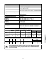
Contents:
IMPORTANT NOTICE .......................................................................................................................................3
IMPORTANT SAFETY INSTRUCTIONS ........................................................................................................3
FACTORS THAT WILL IMPROVE THE PERFORMANCE & LIFE OF YOUR SALT WATER CHLORINATOR ...4
COMMON TERMS: ...........................................................................................................................................5
YOUR NEW SYSTEM: ......................................................................................................................................5
Packing list: ....................................................................................................................................................5
Power supply with door closed .......................................................................................................................6
Power supply control panel ............................................................................................................................7
Electrolytic cell and housing ...........................................................................................................................7
INSTALLATION: ................................................................................................................................................8
Choosing a site: ..............................................................................................................................................8
Sample installation diagram ...........................................................................................................................8
Pipe connections: ...........................................................................................................................................9
Cell power connection: ...................................................................................................................................9
Installing flow switch: ....................................................................................................................................10
Mains power connection: ..............................................................................................................................14
External control connection: .........................................................................................................................14
OPERATION: ................................................................................................................................................... 14
Start-up procedure: ......................................................................................................................................14
Low electrical conductivity: ...........................................................................................................................15
MODBUS physical interface: ........................................................................................................................16
MAINTENANCE: .............................................................................................................................................17
The power supply: ........................................................................................................................................17
The electrolytic cell: ......................................................................................................................................17
How to clean your EcoMatic COMM cell: .....................................................................................................18
Day to day operation: ...................................................................................................................................18
Chlorine production: .....................................................................................................................................19
TECHNICAL SPECIFICATIONS: .....................................................................................................................20
GENERAL INFORMATION ..............................................................................................................................22
Pool water chemistry instructions .................................................................................................................22
SPARE PARTS: ...............................................................................................................................................22
TROUBLESHOOTING: ...................................................................................................................................23
WARRANTY: ...................................................................................................................................................24
Warranty claims: ...........................................................................................................................................24
Exclusions: ...................................................................................................................................................24
ENGLISH

3
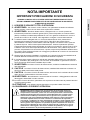
IMPORTANT NOTICE
IMPORTANT SAFETY INSTRUCTIONS
WHEN INSTALLING AND USING THIS ELECTRICAL EQUIPMENT, BASIC SAFETY
PRECAUTIONS SHOULD ALWAYS BE FOLLOWED, INCLUDING THE FOLLOWING:
1. READ AND FOLLOW ALL INSTRUCTIONS
2. WARNING
- To reduce the risk of injury, do not permit children to use this product, unless
they are closely supervised at all times.
3. WARNING - Risk of Electric Shock. Connect only to a circuit protected by a Ground-Fault
Circuit-Interrupter (GFCI) or Residual Current Device (RCD). Contact a qualied electrician
if you cannot verify that the circuit is protected by a GFCI or RCD. Do not bury or coil the
supply cord.
4. The unit must be connected only to a supply circuit that is protected by a ground-fault
circuit-interrupter (GFCI). Such a GFCI should be provided by the installer and should be
tested on a routine basis. To test the GFCI, push the test button. The GFCI should interrupt
power. Push the reset button. Power should be restored. If the GFCI fails to operate in
this manner, the GFCI is defective. If the GFCI interrupts power to the unit without the test
button being pushed, a ground current is owing, indicating the possibility of an electric
shock. Do not use this unit. Disconnect the unit and have the problem corrected by a
qualied service representative before using.
5. This unit is to be installed in accordance with these installation instructions and any local
Electrical Codes and the requirements of the authority having jurisdiction.
6. The chlorinator must be positioned downstream of all pool equipment including pumps,
heaters, lters, cleaners and so on. Note: If an Ozone generator is installed the injection
point MUST be installed after the cell.
7. WARNING - To reduce the risk of electric shock, replace damaged cord immediately.
8. CAUTION - To reduce the risk of electric shock, install power supply at least 10 feet (3m)
from the inside walls of the pool.
9. CAUTION - To reduce the risk of electric shock, ensure green/yellow earthing conductor
of supply cord is connected to earth.
10. WARNING - Do not energize or operate the unit if the enclosure or cell housing is
damaged or improperly assembled.
11. To reduce the risk of injury, only permit people who have read these instructions to use
this product.
12. CAUTION - Do not use this device with bromide products.
13. SAVE THESE INSTRUCTIONS
WARNING: This appliance is not intended for use by persons (including children)
with reduced physical, sensory or mental capabilities, or lack of experience and
knowledge, unless they have been given supervision or instruction concerning
use of the appliance by a person responsible for their safety. Children should be
supervised to ensure that they don’t play with the appliance. This appliance can be
used by children aged from 8 years and above and persons with reduced physical,
sensory or mental capabilities or lack of experience and knowledge if they have been
given supervision or instruction concerning use of the appliance in a safe way and
understand the hazards involved. Children shall not play with the appliance. Cleaning
and user maintenance shall not be made by children without supervision. If the
supply cord is damaged, it must be replaced by the manufacturer, its service agent or
similarly qualied persons in order to avoid a hazard.
ENGLISH
ENGLISH

4
FACTORS THAT WILL IMPROVE THE PERFORMANCE & LIFE OF YOUR
SALT WATER CHLORINATOR
> PLEASE READ THIS BEFORE OPERATING YOUR CHLORINATOR.
• MAINTAIN THE RECOMMENDED SALT LEVELS:
SALT LEVELS: 3,000 – 36,000ppm (mg/L)
> Run chlorinator at the salt levels stated within this document and on the product to ensure optimum
sanitizer output and cell life.
> Operating this device at low salt levels will damage the cell and reduce its life.
> The chlorinator will not run at full output and the control panel will display red LED indicator warnings
when the salt levels are low.
> If no action is taken to rectify the salt levels, damage to the cell may result which will not be covered
under warranty.
• MONITOR & MAINTAIN YOUR CHLORINATOR CELL:
> To keep your salt water chlorinator in the best possible condition, regular monitoring of the electrolytic
cell is recommended. The ‘Cell’ is the clear plastic housing containing the metal plates.
> During the chlorination process a white powdery Calcium scale may naturally build up on the titanium
plates in the cell. Monitor the cell to prevent excessive scale build up. Excessive scale build-up will
cause damage to your cell, and dramatically reduce its efficiency and lifespan.
> The control panel displays red LED indicator warnings when the cell requires cleaning.
> If Calcium scale builds up please clean the cell, following the cleaning instructions provided on page 18.
> NEVER: Use concentrated acid to clean your cell.
> NEVER: Leave cell in cleaning solution for extended periods of time
> NEVER: Use metal implements, scourers or brushes to clean your cell.
• BALANCED POOL WATER CHEMISTRY:
> Salt levels MUST be maintained at 3,000 – 36,000ppm (mg/L) for optimum performance and lifespan.
> Calcium Hardness levels MUST be kept to the ideal range of 200ppm - 275ppm (mg/L) (for concrete
and tiled pools) and 100-225ppm (mg/L) (for inert surfaces) to prevent excessive scale build up and
damage to equipment.
> pH levels MUST be kept between 7.2 and 7.6 to prevent damage to equipment and pool surfaces and
to obtain optimum sanitizer effectiveness.
> Total alkalinity and stabilizer levels must also be kept in an ideal range. Please refer to the day to day
operation section on page 18 and 19 for more information.
ENGLISH

5
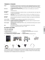
COMMON TERMS
Algae Microscopic forms of plant life which enter the pool by rain, wind and dust. There are
numerous varieties - some are free floating whilst others grow on walls and in cracks and
come in different colours. Some are more resistant to chemical treatment than others.
Bacteria The germs that contaminate your pool. Introduced by swimmers, dust, rain storms
and other elements.
Balanced water The correct ratio of mineral content and pH level that prevents pool water from being
corrosive or scale forming.
Chloramines Compounds formed when chlorine combines with nitrogen from urine, perspiration, etc.
Chloramines cause eye and skin irritation, as well as unpleasant odours.
Chlorine demand The chlorine required to destroy germs, algae and other contaminants in the pool.
Chlorine residual The amount of chlorine remaining after chlorine demand has been satisfied.
This is the reading obtained with your test kit.
Cyanuric acid Also known as stabiliser or conditioner. It reduces dissipation of chlorine by direct
sunlight.
Liquid acid Chemical used to reduce the pH and total alkalinity in the pool water, and for cleaning
Sanitiser cell.
ppm An abbreviation for Parts Per Million the accepted measurement of chemical
concentration in swimming pool water (1 ppm = 1 mg/L).
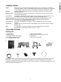
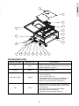
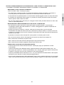
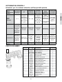
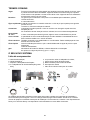
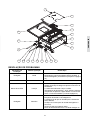
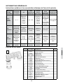
YOUR NEW SYSTEM
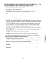
Packing list
a. Power supply;
b. Electrolytic cell;
c. Securing brackets and fasteners;
d. 4 x cell/pipe adaptors (2 pair);
e. 2 x cell adaptor union nuts;
f. Key for front door panel;
g. Waterproofing boot for data connection
h. Flow switch
i. Flow switch circuit cable
a
f g h i
b c d
e
Appropriate details for all these items are contained in the following Installation and Operating Instructions.
Read these in their entirety before switching on the EcoMatic. If you are uncertain as to any of these
Installation and Operating Instructions, please contact your Davey dealer, or the appropriate Davey office as
listed on the back of this document.
ENGLISH
ENGLISH

6
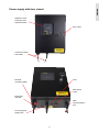
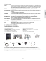
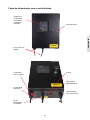
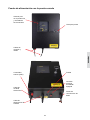
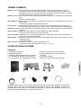
Power supply with door closed
Window to view
production and
operation status
Connection leads
and cables
Key to door
External
controller (ORP)
Electrolytic
cell lead
Incoming power
supply lead
Fuse
Main power
on/off
Data
communications
port
ENGLISH

7
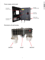
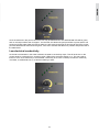
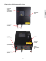
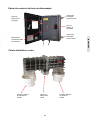
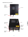
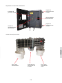
Power supply control panel
Production
indicator LEDs
Production output
control dial
Top right
mounting bracket
Bottom right
mounting bracket
Operation
status LED
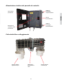
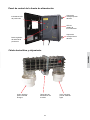
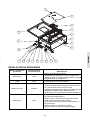
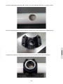
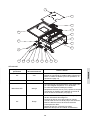
Electrolytic cell and housing
Water inflow
barrel union
Cell power
terminals
Water outflow
barrel union
ENGLISH
ENGLISH

INSTALLATION
Choosing a site
Installation must be done in accordance with any local regulations. When deciding on a position for the unit,
take care to allow for the cable lengths available. The power supply and electrolytic cell are very heavy. Allow
for this during installation. If any components are dropped, damage will occur. The electrolytic cell can be
plumbed in using 80mm (3”), or 50mm (2”) size PVC pressure pipe.
The power supply box should be wall mounted using the brackets provided which are designed for masonry
bolts/wall plugs. The brackets provide a gap between the back of the unit and the wall for enough air flow.
The power supply box should be mounted approximately 1.2 – 1.5m (4ft - 5ft) above ground level and at
least 1.5m (5ft) away from the pool.
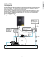
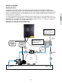
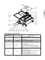
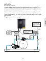
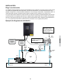
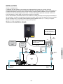
Sample installation diagram
Note: Always fit the
cell so that the Gas
Sensor is on the outlet
side of the cell
Note: Cell must be
installed in a horizontal
position ONLY.
Media
Filter
Suction Line
from Pool
Return Line
to Pool
Cell Cable
Cell
Pump
External
Controller
Sampling
Point
Gas
Sensor
Connector
Flow
Switch
Sampling
Point
External
Controller
(ORP)
Power
Source
8
ENGLISH

9
Pipe connections
Ensure EcoMatic cell housing is installed with sufficient clearance from any and all walls, so as to be easily
removed should service be necessary.
NOTE: If a heater is installed, Davey recommends installing it on a bypass such that water above 30°C
(86°F) does not pass through the cell.
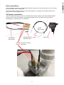
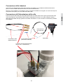
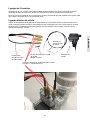
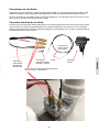
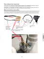
Cell power connection
Push cell sockets (female) from the end of cell lead onto the plugs (male) on the cell as illustrated below
ensuring correct colour configuration. Once attached, tighten nut on cell socket to ensure a tight fit.
Overheating of connection may occur otherwise.
Cell lead from
power supply
Flow switch circuit
(female & male)
Cell gas
sensor socket
Flow switch
Cell power terminal connectors
(2 black, 1 red/white)
ENGLISH
ENGLISH

10
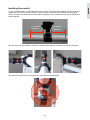
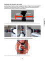
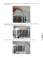
Installing flow switch
Locate a suitable position to install the flow switch. The flow switch should be installed on a straight section
of pipe with a minimum of 5 pipe diameters, in either direction, between the flow switch and any pumps,
valves, or fittings. This will ensure that the paddle is exposed to non-turbulent flow and giving a steady and
stable response.
FLOWSWITCHINSTALLATION–SCMAX
Locateasuitablepositiontoinstalltheflowswitch.Theflowswitchshouldbeinstalledonastraightsectionofpipe
withaminimumof5pipediameters,ineitherdirection,betweentheflowswitchandanypumps,valves,orfittings.
Thiswillensurethatthepaddleisexposedtonon-turbulentflowandgivingasteadyandstableresponse.
Theflowswitchcanbeinstalledinverticalorhorizontalpipes,eitheronthesideoronthetopofthepipe.
Theflowswitchshouldnotbemountedontheundersideofhorizontalpipes.
5xpipedia.
minimum.
5xpipedia.
minimum.
The ow switch can be installed in vertical or horizontal pipes, either on the side or on the top of the pipe.
FLOWSWITCHINSTALLATION–SCMAX
Locateasuitablepositiontoinstalltheflowswitch.Theflowswitchshouldbeinstalledonastraightsectionofpipe
withaminimumof5pipediameters,ineitherdirection,betweentheflowswitchandanypumps,valves,orfittings.
Thiswillensurethatthepaddleisexposedtonon-turbulentflowandgivingasteadyandstableresponse.
Theflowswitchcanbeinstalledinverticalorhorizontalpipes,eitheronthesideoronthetopofthepipe.
Theflowswitchshouldnotbemountedontheundersideofhorizontalpipes.
5xpipedia.
minimum.
5xpipedia.
minimum.
The ow switch should not be mounted on the underside of horizontal pipes.
FLOWSWITCHINSTALLATION–SCMAX
Locateasuitablepositiontoinstalltheflowswitch.Theflowswitchshouldbeinstalledonastraightsectionofpipe
withaminimumof5pipediameters,ineitherdirection,betweentheflowswitchandanypumps,valves,orfittings.
Thiswillensurethatthepaddleisexposedtonon-turbulentflowandgivingasteadyandstableresponse.
Theflowswitchcanbeinstalledinverticalorhorizontalpipes,eitheronthesideoronthetopofthepipe.
Theflowswitchshouldnotbemountedontheundersideofhorizontalpipes.
5xpipedia.
minimum.
5xpipedia.
minimum.
ENGLISH

11
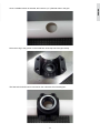
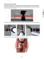
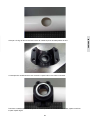
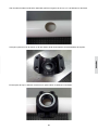
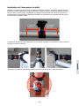
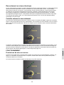
Once a suitable location is selected, drill a 32mm (1¼") diameter hole in the pipe.
Onceasuitablelocationisselected,drilla32mmdiameterholeinthepipe.
PlacetheO-ringinthegrooveontheinsidefaceofthetophalfofthepipeclamp.
Placethetophalfofthepipeclampontothepipeensuringthattheholeinthepipeclampisalignedwiththeholein
thepipe.
Place the o-ring in the groove on the inside face of the top half of the pipe clamp.
Onceasuitablelocationisselected,drilla32mmdiameterholeinthepipe.
PlacetheO-ringinthegrooveontheinsidefaceofthetophalfofthepipeclamp.
Placethetophalfofthepipeclampontothepipeensuringthattheholeinthepipeclampisalignedwiththeholein
thepipe.
The ow switch should not be mounted on the underside of horizontal pipes.
Onceasuitablelocationisselected,drilla32mmdiameterholeinthepipe.
PlacetheO-ringinthegrooveontheinsidefaceofthetophalfofthepipeclamp.
Placethetophalfofthepipeclampontothepipeensuringthattheholeinthepipeclampisalignedwiththeholein
thepipe.
ENGLISH
ENGLISH

12
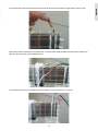
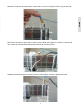
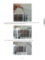
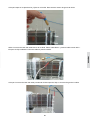
Position the lower half of the pipe clamp onto the pipe and secure with the fasteners provided. Tighten suf-
ciently to prevent leakage.
Positionthelowerhalfofthepipeclampontothepipeandsecurewiththefastenersprovided.Tightensufficiently
topreventleakage.
ApplyTeflontapetothethreadontheflowswitchandscrewtheflowswitchintothepipeclamp.Tightentheflow
switchusingthespannerflatsonthebody.Avoidtighteningtheswitchviatheelectricalenclosureasthiscan
damagetheswitch.
Alignmentoftheswitchiscriticaltocorrectoperation.Theswitchshouldbeinlinewiththepipeandtheflowarrow
inthedirectionofflow.
Removethelidontheelectricalenclosureandinsertthewiresintothecableentry.Connectthewirestothe
terminalslabelled“COMM”and“NO”.
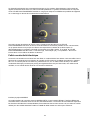
Apply Teon tape to the thread on the ow switch and screw the ow switch into the pipe clamp. Tighten the
ow switch using the spanner ats on the body. Avoid tightening the switch via the electrical enclosure as this
can damage the switch.
Positionthelowerhalfofthepipeclampontothepipeandsecurewiththefastenersprovided.Tightensufficiently
topreventleakage.
ApplyTeflontapetothethreadontheflowswitchandscrewtheflowswitchintothepipeclamp.Tightentheflow
switchusingthespannerflatsonthebody.Avoidtighteningtheswitchviatheelectricalenclosureasthiscan
damagetheswitch.
Alignmentoftheswitchiscriticaltocorrectoperation.Theswitchshouldbeinlinewiththepipeandtheflowarrow
inthedirectionofflow.
Removethelidontheelectricalenclosureandinsertthewiresintothecableentry.Connectthewirestothe
terminalslabelled“COMM”and“NO”.
Alignment of the switch is critical to correct operation. The switch should be in line with the pipe and the ow
arrow in the direction of ow. Remove the lid on the electrical enclosure and insert the wires into the cable
entry. Connect the wires to the terminals labelled “COMM” and “NO”.
Positionthelowerhalfofthepipeclampontothepipeandsecurewiththefastenersprovided.Tightensufficiently
topreventleakage.
ApplyTeflontapetothethreadontheflowswitchandscrewtheflowswitchintothepipeclamp.Tightentheflow
switchusingthespannerflatsonthebody.Avoidtighteningtheswitchviatheelectricalenclosureasthiscan
damagetheswitch.
Alignmentoftheswitchiscriticaltocorrectoperation.Theswitchshouldbeinlinewiththepipeandtheflowarrow
inthedirectionofflow.
Removethelidontheelectricalenclosureandinsertthewiresintothecableentry.Connectthewirestothe
terminalslabelled“COMM”and“NO”.
ENGLISH

13
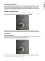
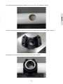
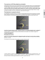
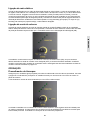
Fit the lid onto the electrical enclosure and secure via the screw. Disconnect the gas sensor from the cell.
Fitthelidontotheelectricalenclosureandsecureviathescrew.
Disconnectthegassensorfromthecell.
Removethebrassconnectorfromthewhitewireonthecellcable.Stripthewhitewireandattachtothebrown
wirefromtheflowswitchviathesuppliedcrimp.
Fitthebrassconnectorontheleadfromtheflowswitchontothegassensoronthecell.
Remove the brass connector from the white wire on the cell cable. Strip the white wire and attach to the brown
wire from the ow switch via the supplied crimp.
Fitthelidontotheelectricalenclosureandsecureviathescrew.
Disconnectthegassensorfromthecell.
Removethebrassconnectorfromthewhitewireonthecellcable.Stripthewhitewireandattachtothebrown
wirefromtheflowswitchviathesuppliedcrimp.
Fitthebrassconnectorontheleadfromtheflowswitchontothegassensoronthecell.
Fit the brass connector on the lead from the ow switch onto the gas sensor on the cell.
Fitthelidontotheelectricalenclosureandsecureviathescrew.
Disconnectthegassensorfromthecell.
Removethebrassconnectorfromthewhitewireonthecellcable.Stripthewhitewireandattachtothebrown
wirefromtheflowswitchviathesuppliedcrimp.
Fitthebrassconnectorontheleadfromtheflowswitchontothegassensoronthecell.
ENGLISH
ENGLISH

14
Mains power connection
The power supply has a power cord attached to the bottom panel. The power cord should be connected
to mains power using the correct sized male plug or by hardwiring straight into the control box. The earth
must be connected. The GPO (General Purpose Outlet) / pool equipment control box, to which the unit
is connected should be protected by a Residual Current Device (RCD Safety Switch), see local electrical
regulations. The electrical supply to the unit should be interlocked to the main pump(s). That is, if the main
pump(s) are not operational, power is turned off.
External control connection
The external control feature is a means of controlling the EcoMatic chlorinator’s output from an external
controller. This can take the form of a timer, residual chlorine controller, or ORP monitor. The production
LED’s will light up to show that the external controller has the cell power turned ON.
The external control input requires normally open (NO), voltage free contacts, where open contacts
signal the chlorinator output is OFF and closed contacts signal the chlorinator output is ON. The external
controller’s output is connected to the terminals located at the base of the chlorinator as shown on page 6.
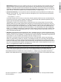
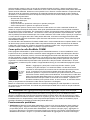
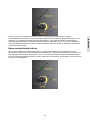
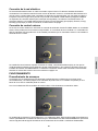
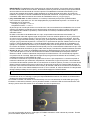
OPERATION
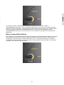
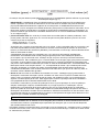
Start-up procedure
Ensure water flow through cell housing is above recommendations, see page 21. The production indicator is
a meter made up of a bar of five LEDs in the middle of the control panel.
Normal cell operation is indicated by five green LEDs being on.
The unit is fitted with an electronic control and warning system. This regulates the output of the Unit to a
preset maximum. The warning system consists of an OPERATION LED which will glow Red to indicate
possible faults with the Unit or damaging operating conditions.
ENGLISH

15
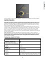
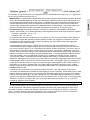
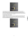
Once the salt level in the pool is correct the unit may be switched ON. The OPERATION LED will be green,
and no cell output will be seen for approx. 120 seconds, this allows the pump and filter to prime and the cell
housing to fill with water. After this start-up delay, the bar meter should light up showing all five LEDs. At this
point the OPERATION LED should be green; if it is red it indicates that there is a problem and please refer to
the table below.
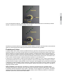
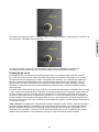
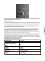
Low electrical conductivity
As the salt concentration in the water is diluted, the water’s conductivity drops. This will be shown on the
control panel by a reduction from 5 working green LEDs of the production display, to 4. This may reduce
further to 3 etc. A low salt level (or low electrical conductivity to be more accurate) can also be created by
cold water, a calcified salt cell, or a cell that’s starting to wear.
ENGLISH
ENGLISH

16
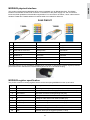
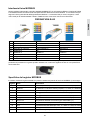
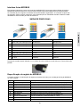
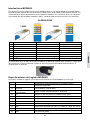
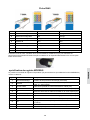
MODBUS physical interface
This product implements the MODBUS RTU protocol standard over an RS485 interface. The RS485
interface is accessible via the RJ45 connector on the bottom of the power supply unit. Pin connections
follow the official guidelines of the Modbus Organisation. Pin connections as follows, colour codes used for
standard T-568A and T-568B varieties of network cable are included for reference.
RJ45 PINOUT
Pin Function T-568A T-568B
1 Reserved for future use Green/white Orange/white
2 Reserved for future use Green Orange
3 Reserved for future use Orange/white Green/white
4 MODBUS B Blue Blue
5 MODBUS A Blue/white Blue/white
6 Reserved for future use Orange Green
7 5V @ 100mA max Brown/white Brown/white
8 0V ground Brown Brown
The RJ45 interface of your ECOMATIC COMM series chlorinator is designed to maintain ingress protection
performance when used with the included sealing boot over an un-booted RJ45 plug.
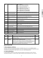
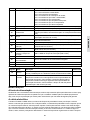
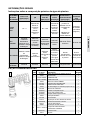
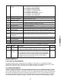
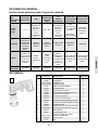
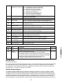
MODBUS register specification
The product consists of holding registers which can be read (using MODBUS function 3) as below:
Register Name Description
1 Start delay How long till start-up delay is complete (seconds)
2 Direction The direction the cell is running (0=off, 1=forward, 2=reverse)
3 Run Current How much current is running through cell (mA)
4 V1 Voltage on one side of cell cable at PCBA (mV)
5 V2 Voltage on other side of cell cable at PCBA (mV)
6 Bridge Temp Temperature in high current area of PCBA (°C)
7 Micro Temp Temperature in logic control area of PCBA (°C)
8 Pot Position Position of output control knob (0 - 1024)
9 DIPS PCBA DIPs setting (b0 = DIP1; b1 = DIP2; b2 = DIP3; b3 = DIP4)
10 ORP Whether ORP input is triggered (0=false; 1=true)
ENGLISH

17
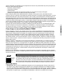
11 TDS Calculated TDS (PPM)
12 Current Warnings/Faults 0x00 = none;
0x01 = low conductivity warning;
0x02 = high conductivity warning;
0x80 = flow switch shut-down;
0x81 = low conductivity shut-down;
0x82 = over-current shut-down;
0x83 = bridge temperature shut-down;
0x84 = micro temperature shut-down;
0x85 = unexpected fault shut-down;
13 Time to Clear Time before fault is cleared and re-start attempted (s)
14 Set Current What the unit is pre-set to regulate current to when at 100% (mA)
15 Target Current
What current the unit is currently regulating towards (allowing for
faults, ramping up/down at start-up/shut-down) (mA)
16 Duty Calculated duty based on Pot Position (% time on in 10 min block)
17 Rise/Fall MSB is time (s) of start-up ramp; LSB is time (s) of shut-down ramp
18 Reverse Time How long the reversal period of the cell is (minutes)
19 Uptime LSBs Lowest 16-bits of uptime (time unit has been powered in minutes)
20 Runtime LSBs Lowest 16-bits of runtime (time cell has been active in minutes)
21 Uptime and Runtime MSBs MSB is Uptime MSB (total 24-bit)
LSB is Runtime MSB (total 24-bit)
22 Microcontroller ID ID number of embedded micro-controller
23 Microcontroller Revision Revision number of embedded micro-controller
24 Software Version Software Version
102 Serial Number Unique serial number
The following registers have write access (using MODBUS function 6) available: -
Register Name Description Allowable
16 Duty
Set duty output (% time on in 10 min block). Re-sets if control knob
physically rotated.
0 – 100
18 Reverse Time Set reversal time in minutes.
Shorter reversal times mean less opportunity for scale build-up but
reduce plate life.
Longer reversal times mean more opportunity for scale build-up but
increase plate life.
Default is 480 minutes (8 hours)
240 - 720
MAINTENANCE
The power supply
Little maintenance is typically required, however it is essential that the wall to which the unit is installed be
sprayed (not the unit itself) periodically with a good surface type insect repellent, since penetration by insects
may cause damage which is not covered by your warranty.
The electrolytic cell
The EcoMatic COMM system uses reverse polarity cleaning system to clean the cell and reduce operational
maintenance. In ideal conditions reverse polarity systems will require little or no manual cleaning, however
in areas with hard water (high calcium hardness), reverse polarity systems may require occasional manual
cleaning. Calcium and other minerals are deposited on the cell plates as electrolysis takes place. This build
up will interfere with the flow of electrical current and water in the cell and thus lowers sanitizer production.
ENGLISH
ENGLISH

18
It is essential to inspect the cell regularly and clean when necessary. The rate at which deposits will form on
the plates differs with each pool and can be influenced by the following:
• Calcium hardness of the water;
• Water temperature;
• pH control;
• Water which has been chlorinated with calcium hypochlorite for an extended period
• Calcium in the plaster surfaces of a concrete pool.
These conditions can vary a lot. Check the cell at least weekly to begin with to see if any deposits appear on
the plates. You will then be able to determine the cleaning cycle necessary for your pool (obviously more in
summer). The intervals between cleaning could get longer to the point where cleaning is only necessary a
couple of times each year. One exception is the use of bore water or ground water, in which case cleaning
may need to be as frequent as once a week. If the cell remains dormant for a period, or there is evidence of
rust within the cell or on the cell plates, an acid wash clean of the cell is required prior to use of the sanitizing
system (please refer to next section – How to clean your EcoMatic COMM cell).
Life of EcoMatic COMM electrolytic cells will vary substantially from one installation to another due to
variations in operating time, water quality and composition, system and cell maintenance. Please ensure
that when a cell replacement is necessary you use the correct genuine EcoMatic COMM replacement cell to
match your system.
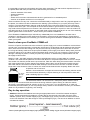
How to clean your EcoMatic COMM cell
First turn off power, then disconnect the cell from the power supply unit. In some installations such as above
ground pools, it maybe necessary to isolate the cell housing in the plumbing and de-pressurize the pipework.
Then, remove from the cell housing from the pool return line by undoing the unions. Take care not to lose
the o-rings and always make sure the pump and EcoMatic power supply is turned off. Always wear personal
protective clothing such as rubber gloves and glasses while cleaning your cell. Inspect the cell for obvious
damage. If damage is present, consult your place of purchase, or nearest Davey representative from the
back page of this manual.
Method 1: Add 1 part (28% strength) Hydrochloric Acid (Muriatic Acid) to 10 parts water in a suitable
container. The cell should be placed on a surface that allows it to be placed upside-down to form a U shape.
The solution can then be poured into the up-turned cell. Take care when doing this as the solution can foam
and create a spill which must be cleaned up by dilution. When clean, the cell should be rinsed thoroughly
with water and the connections should be dried carefully to avoid connector corrosion. It should not take
longer than a few minutes to clean. If it does, the cell should be cleaned more frequently. Return the cell to
its position and re-connect it.
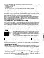
Method 2: As an alternative, an approved commercial cell cleaning solution can be
used several times effectively. Frequent cleaning of cell is required in areas with
water containing high iron content.
WARNING: Never add water to acid. Always add acid to water
The weak acid solution can be stored in a safe place (where children cannot
access it) and re-used several times before becoming ineffective (saves having to make the solution
each time). Avoid getting the acid solution on skin or in your eyes. If you accidentally do so, wash off
immediately with fresh water (or use the pool/spa water). Please do not hesitate to contact your EcoMatic
dealer for any assistance regarding ‘cell’ cleaning.
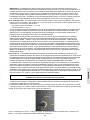
Day to day operation
• Stabiliser: Measure the stabiliser level using an appropriate test kit. It should be between 25-50ppm
(mg/L). Follow the directions for adding it or load it directly into the pool pump inlets. If there is some
stabiliser present, but it is below 30ppm (mg/L), add 20ppm (mg/L) to the pool and re-measure the level
once it has dissolved. Then add enough to make up the 50ppm (mg/L). The amount of stabilizer to add is
calculated as follows:
For example:
A 50m3 (13,200 gallons) pool has 30ppm (mg/L) stabiliser present. Adding 1kg (35 ounces) will raise to 50ppm (mg/L).
3%
Active
Strength
acid
in
water
ENGLISH

19
IMPORTANT: Stabiliser is for use in outdoor pools only. It is used to reduce the loss of chlorine due to the
effect of sunlight. It should not be used in indoor pools as it may adversely affect pool chlorine demand.
Stabiliser is very slow to dissolve and if loaded into the pump inlets it can sit in the filters for several days.
If the filters are backwashed, it will be lost. Monitor the stabiliser after backwashing. Outdoor pool using an
ORP controller, should have stabilizer levels maintained between 15-25ppm (mg/L).
• pH and Total Alkalinity: A correct pH level must be maintained to prevent problems such as black spot,
staining, cloudy water, etc. An incorrect pH level can damage the pool. Correct pH levels are as follows:
> Concrete & tiled – 7.4 to 7.6
> Inert surfaces – 7.2 to 7.4
If you allow the pH level to rise to 8.0 or above the chlorine required could be as much as three times the
normal amount and can cause increased cell scaling. To lower the pH add Hydrochloric (Muriatic) acid. To
raise the pH level add Sodium Bicarbonate, or Soda Ash.
Total Alkalinity should not be confused with pH, although the two are closely related. The correct Total
Alkalinity buffers the pool water against rapid changes in pH and prevents what is known as pH ‘bounce’
where the pH value rises and falls sharply. It is measured in ppm; the ideal range is 80-120ppm (mg/L) for
concrete or tiled pools and 125-250ppm (mg/L) for other surfaces or refer to your pool professional. You
should use a test kit which includes a test for Total Alkalinity. Low Total Alkalinity can cause unstable pH
levels – i.e. An inability to keep the pH constant may cause staining, etching and corrosion of metals. High
Total Alkalinity will cause constantly high pH levels. To lower, add Hydrochloric Acid (a little at a time). To
raise, add Sodium Bicarbonate.
• Salt levels: Salt levels MUST be maintained at 3,000 – 36,000ppm (mg/L) for optimum performance and
lifespan. Operating the unit with too little salt in the pool will cause damage to your cell. Salt is the essential
element by which your unit operates. Low salt means low chlorine production. This simple rule governs the
total operation of your EcoMatic and insufficient salt WILL damage your cell.
Salt is NOT consumed in the process of producing chlorine or by evaporation. Salt is only lost through
dilution, by backwashing, splash-out, overflow, or by leakage from the pool or plumbing. Rain also dilutes
the salt centration in your pool, therefore salt levels should be checked after heavy rainfall. Colder water
lowers the conductivity of the pool water. This will reduce the unit output and turn the Operation LED red. If
this occurs extra salt should be added or damage to the cell will result. If water temperature is below 15°C
(59°F), it is suggested the EcoMatic unit be switched off.
WARNING: Low salt levels will destroy the coating on the plates and will void all Warranty.
The EcoMatic unit has a built-in warning system to minimize damage resulting from insufficient salt levels,
however, the ultimate responsibility is on the owner to ensure adequate salt levels are maintained all year round.
The EcoMatic will show a low salt alarm at a salt concentration of ~ 3,000ppm (mg/L). The system will continue to
operate, but the display will show an orange operation LED, and less than 5 green LEDs on the “production bar meter”.
At a salt concentration of ~ 2,500ppm, the EcoMatic will enter “low salt cut-out”. At this point the EcoMatic
will stop operating.
ENGLISH
ENGLISH

20
If the low salt alarm, or low salt cut-out is triggered, raising the salt concentration back to within range will
automatically clear the alarms.
Chlorine production
The EcoMatic unit must be run daily to generate enough chlorine to sanitize the pool. If the level is too low
either longer running times are required, or the system control needs to be adjusted higher. Harsh local
conditions such as traffic pollution or windborne dust require different running times, in which case seek
advice from your pool shop. Without enough filtration/chlorination, your pool will never function correctly.
Always run the filtration system when swimming in the pool.
In some cases, you may find your chlorine level to be too high. To determine if this is the case, run your
chlorinator for the suggested times/chlorine production level and test your pool water on the morning after
operation. If your chlorine test shows a high level of chlorine, either the running times can be reduced
slightly, or the system control can be turned down (anti – clockwise). Test your chlorine level again the
following morning at around the same time. If your chlorine level is still high, repeat the above process until
the correct level is attained.
Super Chlorination: Periodically, especially during extremely hot conditions, it may be necessary to
boost the amount of chlorine in your pool in order to maintain absolute sanitation of the water. This can be
achieved by adding either liquid or granulated chlorine. If granulated chlorine is added, the cell must be
checked regularly, since the additives from this product may clog the electrodes. Alternatively, extend the
running time of your EcoMatic.
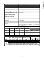
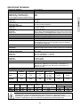
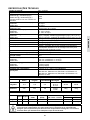
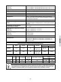
TECHNICAL SPECIFICATIONS
Input voltage: 220 – 240VAC
Supply frequency/phase: 50 – 60Hz / Single phase
Power consumption typical @ 230V:
COMM 500 @ ~4500ppm (mg/L)
COMM 1000 @ ~4500ppm (mg/L)
Efficiency improves with increased salinity
250W
500W
Maximum input current (AC):
COMM 500
COMM 1000
1.6 Amps
3.0 Amps
Fuse type:
COMM 500/1000 5.0 Amps slow blow
Output to cell (DC):
COMM 500
COMM 1000
22 - 24V, 9 Amps
24 - 26V, 19 Amps
Chlorine gas output:
COMM 500
COMM 1000
50g/h (1.2kg/day, 2.65lbs/d) @ 5,000ppm (mg/L) @ 25°C (77°F)
100g/h (2.4kg/day, 5.29lbs/d) @ 5,000ppm (mg/L) @ 25°C (77°F)
ENGLISH
A página está carregando...
A página está carregando...
A página está carregando...
A página está carregando...
A página está carregando...
A página está carregando...
A página está carregando...
A página está carregando...
A página está carregando...
A página está carregando...
A página está carregando...
A página está carregando...
A página está carregando...
A página está carregando...
A página está carregando...
A página está carregando...
A página está carregando...
A página está carregando...
A página está carregando...
A página está carregando...
A página está carregando...
A página está carregando...
A página está carregando...
A página está carregando...
A página está carregando...
A página está carregando...
A página está carregando...
A página está carregando...
A página está carregando...
A página está carregando...
A página está carregando...
A página está carregando...
A página está carregando...
A página está carregando...
A página está carregando...
A página está carregando...
A página está carregando...
A página está carregando...
A página está carregando...
A página está carregando...
A página está carregando...
A página está carregando...
A página está carregando...
A página está carregando...
A página está carregando...
A página está carregando...
A página está carregando...
A página está carregando...
A página está carregando...
A página está carregando...
A página está carregando...
A página está carregando...
A página está carregando...
A página está carregando...
A página está carregando...
A página está carregando...
A página está carregando...
A página está carregando...
A página está carregando...
A página está carregando...
A página está carregando...
A página está carregando...
A página está carregando...
A página está carregando...
A página está carregando...
A página está carregando...
A página está carregando...
A página está carregando...
A página está carregando...
A página está carregando...
A página está carregando...
A página está carregando...
A página está carregando...
A página está carregando...
A página está carregando...
A página está carregando...
A página está carregando...
A página está carregando...
A página está carregando...
A página está carregando...
A página está carregando...
A página está carregando...
A página está carregando...
A página está carregando...
A página está carregando...
A página está carregando...
A página está carregando...
A página está carregando...
A página está carregando...
A página está carregando...
A página está carregando...
A página está carregando...
A página está carregando...
A página está carregando...
A página está carregando...
A página está carregando...
A página está carregando...
A página está carregando...
A página está carregando...
A página está carregando...
-
 1
1
-
 2
2
-
 3
3
-
 4
4
-
 5
5
-
 6
6
-
 7
7
-
 8
8
-
 9
9
-
 10
10
-
 11
11
-
 12
12
-
 13
13
-
 14
14
-
 15
15
-
 16
16
-
 17
17
-
 18
18
-
 19
19
-
 20
20
-
 21
21
-
 22
22
-
 23
23
-
 24
24
-
 25
25
-
 26
26
-
 27
27
-
 28
28
-
 29
29
-
 30
30
-
 31
31
-
 32
32
-
 33
33
-
 34
34
-
 35
35
-
 36
36
-
 37
37
-
 38
38
-
 39
39
-
 40
40
-
 41
41
-
 42
42
-
 43
43
-
 44
44
-
 45
45
-
 46
46
-
 47
47
-
 48
48
-
 49
49
-
 50
50
-
 51
51
-
 52
52
-
 53
53
-
 54
54
-
 55
55
-
 56
56
-
 57
57
-
 58
58
-
 59
59
-
 60
60
-
 61
61
-
 62
62
-
 63
63
-
 64
64
-
 65
65
-
 66
66
-
 67
67
-
 68
68
-
 69
69
-
 70
70
-
 71
71
-
 72
72
-
 73
73
-
 74
74
-
 75
75
-
 76
76
-
 77
77
-
 78
78
-
 79
79
-
 80
80
-
 81
81
-
 82
82
-
 83
83
-
 84
84
-
 85
85
-
 86
86
-
 87
87
-
 88
88
-
 89
89
-
 90
90
-
 91
91
-
 92
92
-
 93
93
-
 94
94
-
 95
95
-
 96
96
-
 97
97
-
 98
98
-
 99
99
-
 100
100
-
 101
101
-
 102
102
-
 103
103
-
 104
104
-
 105
105
-
 106
106
-
 107
107
-
 108
108
-
 109
109
-
 110
110
-
 111
111
-
 112
112
-
 113
113
-
 114
114
-
 115
115
-
 116
116
-
 117
117
-
 118
118
-
 119
119
-
 120
120


Davey COMM500 Instruções de operação
- Tipo
- Instruções de operação
- Este manual também é adequado para
em outras línguas
- español: Davey COMM500 Instrucciones de operación
- français: Davey COMM500 Mode d'emploi
- italiano: Davey COMM500 Istruzioni per l'uso
- English: Davey COMM500 Operating instructions
Artigos relacionados

Outros documentos
-
POOL PAPI004206-INTER5 Manual do usuário
-
Zodiac WW000031 Guia de usuario
-
Bestway Chlorinator Manual do proprietário
-
Astralpool CTX Series Instruções de operação
-
HTW BASIC NEO Manual do usuário
-
Calorex I-PAC Guia de instalação
-
Pentair Pool ChemCheck Manual do proprietário
-
LG PDRYCB500.ENCXLEU Manual do proprietário
-
 AquaChek NP207 Instruções de operação
-
 Viron P600 eVo Instruções de operação

