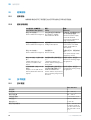
SICK PowerProx Small Analog - WTT190L-Kxxxx Instruções de operação
- Tipo
- Instruções de operação

O P E R A T I N G I N S T R U C T I O N S
PowerProx Small Teach-in – WTT190L-Kxxx
MultiTask photoelectric sensor


Described product
PowerProx Small Teach-in – WTT190L-Kxxxx
Manufacturer
SICK AG
Erwin-Sick-Str. 1
79183 Waldkirch
Germany
Legal information
This work is protected by copyright. Any rights derived from the copyright shall be
reserved for SICK AG. Reproduction of this document or parts of this document is only
permissible within the limits of the legal determination of Copyright Law. Any modifica‐
tion, abridgment or translation of this document is prohibited without the express writ‐
ten permission of SICK AG.
The trademarks stated in this document are the property of their respective owner.
© SICK AG. All rights reserved.
Original document
This document is an original document of SICK AG.
2
8020034.ZX33 | SICK
Subject to change without notice

Contents
1 Safety information............................................................................ 4
1.1 Safety notes.............................................................................................. 4
2 Product description........................................................................... 4
2.1 Intended use............................................................................................. 4
2.2 Dimensional drawing................................................................................ 5
3 Commissioning.................................................................................. 5
3.1 Check the application conditions:........................................................... 5
3.2 Mounting................................................................................................... 6
3.3 Electronics................................................................................................. 6
3.4 Functioning of the programmable input.................................................. 7
3.5 Alignment.................................................................................................. 7
4 Configuration..................................................................................... 7
4.1 Setting the switching output via the teach-in quick access button
(-/Q1) (+/Q2) (Set/Q3)............................................................................. 7
4.2 Setting the switching outputs and other sensor configurations via the
menu......................................................................................................... 8
4.3 Pushbutton lock........................................................................................ 11
5 Troubleshooting................................................................................. 11
5.1 Troubleshooting........................................................................................ 11
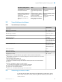
5.2 Table: Fault diagnosis............................................................................... 11
6 Technical data.................................................................................... 11
6.1 Technical data........................................................................................... 11
7 Disassembly and disposal............................................................... 12
8 Maintenance...................................................................................... 12
CONTENTS
8020034.ZX33 | SICK
Subject to change without notice
3

1 Safety information
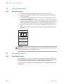
1.1 Safety notes
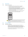
■
Read the operating instructions before commissioning.
■
Connection, mounting, and setting may only be performed by trained specialists.
■
Not a safety component in accordance with the EU Machinery Directive.
■
UL: Only for use in applications in accordance with NFPA 79. These devices shall
be protected by a 1 A fuse suitable for 30 V DC. Adapters listed by UL with connec‐
tion cables are available. Enclosure type 1.
■
When commissioning, protect the device from moisture and contamination.
■
These operating instructions contain information required during the life cycle of
the sensor.
EN/IEC 60825-1:2014
IEC60825-1:2007
LASERKLASSE 1
Laser
1
Maximum pulse power < 64 mW
Puls length: 9 ns
Wavelength: 650 nm
Complies with 21 CFR 1040.10
and 1040.11 except for deviations
pursuant to Laser Notice No. 50,
dated June 24, 2007
ATTENTION
WARNING: Interruption, manipulation or incorrect use can lead to hazardous exposure
due to laser radiation.
2 Product description
2.1 Intended use
The WTT190L-Kxxxx is an opto-electronic photoelectric proximity sensor (referred to as
“sensor” in the following) for the optical, non-contact detection of objects. If the product
is used for any other purpose or modified in any way, any warranty claim against SICK
AG shall become void.
Photoelectric proximity sensor with background suppression and analog distance value
output.
1 SAFETY INFORMATION
4
8020034.ZX33 | SICK
Subject to change without notice

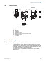
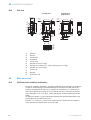
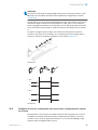
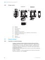
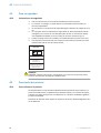
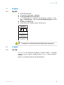
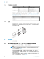
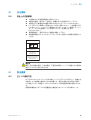
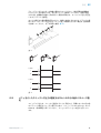
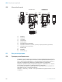
2.2 Dimensional drawing
2
1
4.8
(0.19)
4
3
5
à ß 9
6
7
8
28.3 (1.11)
17
(0.67) 32.8 (1.29)
9
(0.35)
16
(0.63)
44.4 (1.75)
39.2 (1.54)
2.6
(0.1)
3.7 (0.12)
1.2
(0.05)
1.9
(0.07)
Ø 3.1
(0.12)
7
(0.28)
6 (0.24)
2.8 (0.11)
17.4 (0.69)
3
32.8 (1.29)
39.2 (1.54)
2.6
(0.1)
3.1
(0.12)
1.2
(0.05)
1.9
(0.07)
Ø 3.1
(0.12)
7 (0.28)
6 (0.24)
2.8 (0.11)
WTT190L-K2xxx WTT190L-K1xxx
WTT190L-K3xxx
1
Receiver
2
Sender
3
Connection
4
RUN button
5
(+/Q2) button
6
Output display (orange)
7
Stability display (green/red), Q3 output display (orange)
8
Output display (orange)
9
(-/Q1) button
ß
Display
à
(SET/Q3) button
3 Commissioning
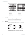
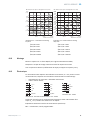
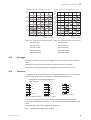
3.1 Check the application conditions:
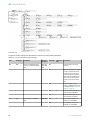
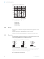
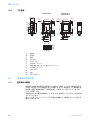
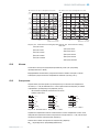
Check the application conditions: Adjust the sensing range and distance to the object
or background and the remission capability of the object according to the correspond‐
ing diagram [H1, H2] (x = sensing range, y = minimum distance between the object and
background in mm (object remission / background remission)). Remission: 6% = black,
90% = white (referring to standard white as per DIN 5033).
The minimum distance (= y) for background suppression can be read from diagram
[H15] as follows:
Example: x = 1,000 mm, y = 20 mm. That is, the background is suppressed at a dis‐
tance of > 20 mm from the sensor.
PRODUCT DESCRIPTION 2
8020034.ZX33 | SICK
Subject to change without notice
5

200
(7.87)
160
(6.3)
120
(4.72)
80
(3.15)
40
(1.57)
0
Min. distance from object to background in mm (inch)
0
1,000
(39.37)
2,000
(78.74)
3,000
(119.11)
Distance in mm (inch)
1
2
3
5
4
Figure: H-1 - Small teach and analog 6%/90%
16%/90% AVG1
26%/90% AVG4
36%/90% AVG16
46%/90% AVG64
56%/90% AVG256
180
(7.09)
160
(6.03)
120
(4.72)
80
(3.15)
40
(1.57)
140
(5.51)
100
(3.94)
60
(2.36)
20
(0.79)
0
Min. distance from object to background in mm (inch)
0
1,000
(39.37)
2,000
(78.74)
3,000
(118.11)
Distance in mm (inch)
1
2
3
4
5
Figure: H-2 - Small teach and analog 90%/90%
190%/90% AVG1
290%/90% AVG4
390%/90% AVG16
490%/90% AVG64
590%/90% AVG256
3.2 Mounting
Mount the sensor using a suitable mounting bracket (see the SICK range of acces‐
sories).
Note the sensor's maximum permissible tightening torque of 0.8 Nm.
Note the preferred direction of the object relative to the sensor [F].
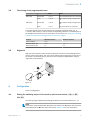
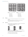
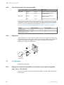
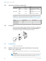
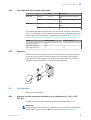
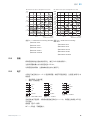
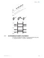
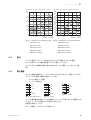
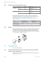
3.3 Electronics
The sensors must be connected in a voltage-free state (U
V
= 0 V). The information in
the graphics [B] must be observed, depending on the connection type:
– Male connector connection: pin assignment
– Cable: wire color
+(L+)
–(M)
Q2
Q1
Q3/MF
in
brn
wht
blk
gra
blu
Figure: B - WTT190L-K15x4
+(L+)
–(M)
Q2
Q1
Q3/MF
in
brn
wht
blk
gra
blu
1
2
3
4
5
Figure: B-2 - -K35x4
Q1
4
+(L+)
–(M)
Q2/MF
in
brn
wht
blk
blu
1
2
3
Figure: B-3 - K22x3
Only apply voltage/switch on the voltage supply (U
V
> 0 V) once all electrical connec‐
tions have been established. The green LED indicator lights up on the sensor.
Explanations of the connection diagram (Graphic B):
MF
in
= multifunctional, programmable input.
3 COMMISSIONING
6
8020034.ZX33 | SICK
Subject to change without notice

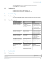
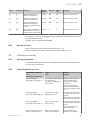
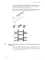
3.4 Functioning of the programmable input
Value Notes
PNP mode Deactivated < 5.0 V Also deactivated when not connected
Active > 10.0 V Max. applied voltage not higher than
UV
NPN mode Deactivated > 10.0 V Max. applied voltage not higher than
UV
Active < 4.0 V Also active when not connected
The programmable input must be active for the durations specified below (e.g., U
> 10.0 V in PNP mode ) in order to set the corresponding functions. For a description of
the available functions and how to select them via the menu, see „Setting the switching
outputs and other sensor configurations via the menu“, page 8
Function Minimum duration Maximum duration
Laser shutdown 4 ms -
External teach-in Q1
External teach-in Q2
4 ms
1 s
1 s
2 s
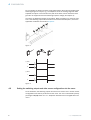
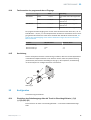
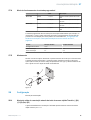
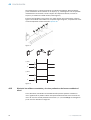
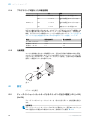
3.5 Alignment
Align the sensor with the object. Select the position so that the red emitted light beam
hits the center of the object. You must ensure that the optical opening (front screen) of
the sensor is completely clear [F]. We recommend making the adjustments using an
object with a low remission.
Figure: E
4 Configuration
Perform configuration:
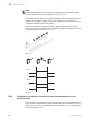
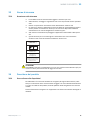
4.1 Setting the switching output via the teach-in quick access button (-/Q1) (+/Q2)
(Set/Q3)
The sensing range is adjusted by pressing the teach-in quick access button for > 1 s.
NOTE
The teach-in quick access button (Set/Q3) is only active if the OUT option has previously
been selected in the MF menu item. See section chapter 4.2 for more information
COMMISSIONING 3
8020034.ZX33 | SICK
Subject to change without notice
7

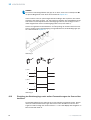
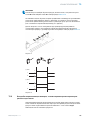
Do not operate the teach-in buttons using sharp objects. We recommend placing the
s
witching range in the object, e.g., see Graphic F. Once the sensing range has been
adjusted, the object is removed from the path of the beam, which causes the back‐
ground to be suppressed and the switching output to change (see Graphic C).
The sensor is adjusted and ready for operation. Refer to Graphic C to check the func‐
tion. If the switching output fails to behave in accordance with Graphic C, check the
application conditions. See section chapter 5.
Q1
Q2
Q3
Figure: F
Q (PNP)
Q (NPN)
L
L
D
D
1
0
1
0
1
0
1
0
Figure: C
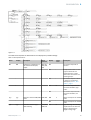
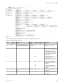
4.2 Setting the switching outputs and other sensor configurations via the menu
As an alternative, the switching outputs can also be set via the menu. Further sensor
c
onfigurations can also be performed via the menu. The menu is accessed by briefly
pressing the Set/Q3 button for < 1 s. Graphic K describes how to navigate within the
menu.
4 C
ONFIGURATION
8
8020034.ZX33 | SICK
Sub
ject to change without notice

Figure 1: K
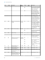
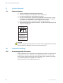
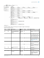
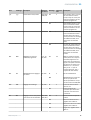
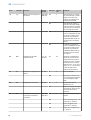
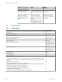
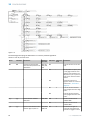
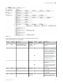
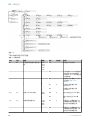
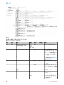
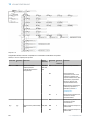
The table below explains the abbreviations and displays the possible settings.
Table 1: Teach parameter list
Name Display Description Value
selection
Display Initial
value
Description
MF MF Enables the configuration of
the multifunctional input/
output.
OFF, OUT,
TCH, LSR,
LSN
oFF The external input has no
function.
out In 5-pin devices: Pin 5 or the
gray wire functions as a
switching output. In 4-pin
devices: Pin 2 functions as a
switching output.
tch The external input is a teach-
in input. For a functional
description, see see „Elec‐
tronics“, page 6
LSr X The external input functions
as a laser shutdown, high-
active.
LSn The external input functions
as a laser shutdown, low-
active.
N_P n_P Switchover between PNP/NPN
mode.
PNP, NPN PnP X Inputs and outputs are in PNP
mode.
nPn Inputs and outputs are in NPN
mode.
L_D L_d Switchover between light/
dark switching
LON, DON,
STB, STD
Lon X Light switching: The switching
output switches on when the
object is closer than the
taught sensing range.
CONFIGURATION 4
8020034.ZX33 | SICK
Subject to change without notice
9

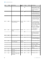
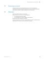
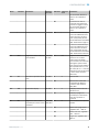
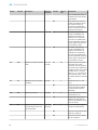
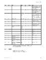
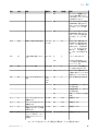
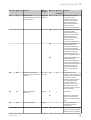
Name Display Description Value
selection
Display Initial
value
Description
don Dark switching: The switching
output switches off when the
object is closer than the
taught sensing range.
Stb The switching output Q1
issues the stability of the
measured value acquisition
(therefore corresponds to the
LED stability display). Light
switching functionality.
Std The switching output Q1
issues the stability of the
measured value acquisition
(therefore corresponds to the
LED stability display). Dark
switching functionality.
AVG AUG Setting the moving arithmetic
average
1, 4, 16,
64, 256
64 64 Sets the number of values
across which a moving arith‐
metic average is established
when the signal is output.
This smooths the signal out‐
put. The possible values are
1, 4, 16, 64, or 256 (e.g., 1 =
no averaging, 256 = average
across 256 values)
RST rSt Reset to factory settings NO, YES no X No reset.
YES Reset all values to factory set‐
tings with the exception of the
PNP/NPN selection.
DSP dSP Display settings ON, OFF on X Display shows display value in
cm.
oFF Display switches off 30 sec‐
onds after an operating but‐
ton was last pressed.
DLY dLY Setting the time functions for
the switching outputs.
OFF, OFD,
OND, SHT
oFF X No time function activated.
oFd Switch-off delay, adjustable
from 0 … 999 ms.
ond Switch-on delay, adjustable
from 0 … 999 ms.
Sht Single shot, adjustable from 0
… 999 ms.
Q_1 q_I Distance assignment for
switching output Q1.
0 … 300 300 300 Value range 0 … 300
Q_2 q_2 Distance assignment for
switching output Q2.
0 … 300 300 300 Value range 0 … 300
Q_3 q_3 Distance assignment for
switching output Q3. (only in
5-pin devices)
0 … 300 300 300 Value range 0 … 300
OFS oFS Defines the offset of the
switching threshold (cm) dur‐
ing the teach-in, based on the
currently measured value.
-50 … +50 0 0 Value range -50 … +50
4 CONFIGURATION
10
8020034.ZX33 | SICK
Subject to change without notice

If the switching outputs are to be set via the menu, adjust the Q_X entries.
Press the Run button to leave the menu.
4.3 Pushbutton lock
Pushbutton lock on: Press the (Run) button for > 1 s
Pushbutton lock off: Press the (Run) button again for > 1 s
5 Troubleshooting
5.1 Troubleshooting
The Troubleshooting table indicates measures to be taken if the sensor stops working.
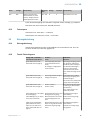
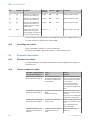
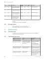
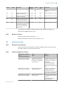
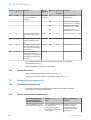
5.2 Table: Fault diagnosis
LED indicator/fault pattern /
LED indicator/fault pattern
Cause /
Cause
Measures /
Measures
Green LED does not light up /
Green LED does not light up
No voltage or voltage below
the limit values /
No voltage or voltage below
the limit values
Check the power supply,
check all electrical connec‐
tions (cables and plug connec‐
tions) /
Check the power supply,
check all electrical connec‐
tions (cables and plug connec‐
tions)
Green LED does not light up /
Green LED does not light up
Voltage interruptions /
Voltage interruptions
Ensure there is a stable power
supply without interruptions /
Ensure there is a stable power
supply without interruptions
Green LED does not light up /
Green LED does not light up
Sensor is faulty /
Sensor is faulty
If the power supply is OK,
replace the sensor /
If the power supply is OK,
replace the sensor
Yellow LED lights up, no object
in the path of the beam /
Yellow LED lights up, no object
in the path of the beam
Distance between the sensor
and the background is too
short /
/ Distance between the sen‐
sor and the background is too
short
Reduce the sensing range,
see graphic F /
Reduce the sensing range,
see graphic F
Object is in the path of the
beam, yellow LED does not
light up /
Object is in the path of the
beam, yellow LED does not
light up
Distance between the sensor
and the object is too long or
sensing range is set too
short /
Distance between the sensor
and the object is too long or
sensing range is set too short
Increase the sensing range,
see graphic F /
Increase the sensing range,
see graphic F
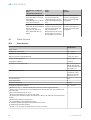
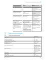
6 Technical data
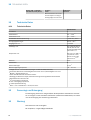
6.1 Technical data
WTT190L-Kxxx
Laser class 1
CONFIGURATION 4
8020034.ZX33 | SICK
Subject to change without notice
11

WTT190L-Kxxx
Sensing range 0.2 ... 3.0 m
1)
Sensing range max. 0.2 ... 3.0 m
1)
Light spot diameter/distance ~ 12.0 mm / 3.0 m
Supply voltage V
S
DC 10 ... 30 V
2)
Output current I
max.
≤ 100 mA
Max. switching frequency AVG 1: 833 Hz, AVG 4:
500 Hz, AVG 16: 147
Hz, AVG 64: 38 Hz, AVG
256: 10 Hz
3)
4)5)
Max. response time AVG 1: 0.6 ms, AVG 4: 1
ms, AVG 16: 3.4 ms,
AVG 64: 13 ms, AVG
256: 51.4 ms
6)
4)5)
Enclosure rating IP 67
Protection class III
Circuit protection A, B, C
7)
Ambient operating temperature -30 ... +50 °C
8)
1)
Object with 6 % ... 90 % remission (based on standard white DIN 5033)
2)
Limit value; operation in short-circuit protection mains max. 8 A; residual ripple max. 5 Vss
3)
With light / dark ratio 1:1
4)
Can be influenced via average filter.
5)
Dependent on distance to object, distance to background, and switching threshold selected
6)
Signal transit time with resistive load
7)
A = UV-connections reverse polarity protected
B = inputs and output reverse-polarity protected
C = Interference suppression
8)
Where TU < –10 °C: warm-up time < 10 min; UV>=24 V.
7 Disassembly and disposal
The sensor must be disposed of according to the applicable country-specific regula‐
tions. Efforts should be made during the disposal process to recycle the constituent
materials (particularly precious metals).
8 Maintenance
SICK sensors are maintenance-free.
We recommend doing the following regularly:
•
Clean the external lens surfaces
•
Check the screw connections and plug-in connections
No modifications may be made to devices.
Subject to change without notice. Specified product properties and technical data are
not written guarantees.
7 DISASSEMBLY AND DISPOSAL
12
8020034.ZX33 | SICK
Subject to change without notice


Beschriebenes Produkt
PowerProx Small Teach-in - WTT190L-Kxxxx
Hersteller
SICK AG
Erwin-Sick-Str. 1
79183 Waldkirch
Deutschland
Rechtliche Hinweise
Dieses Werk ist urheberrechtlich geschützt. Die dadurch begründeten Rechte bleiben
bei der Firma SICK AG. Die Vervielfältigung des Werks oder von Teilen dieses Werks ist
nur in den Grenzen der gesetzlichen Bestimmungen des Urheberrechtsgesetzes zuläs‐
sig. Jede Änderung, Kürzung oder Übersetzung des Werks ohne ausdrückliche schriftli‐
che Zustimmung der Firma SICK AG ist untersagt.
Die in diesem Dokument genannten Marken sind Eigentum ihrer jeweiligen Inhaber.
© SICK AG. Alle Rechte vorbehalten.
Originaldokument
Dieses Dokument ist ein Originaldokument der SICK AG.
14
8020034.ZX33 | SICK
Subject to change without notice

Inhalt
9 Zu Ihrer Sicherheit............................................................................. 16
9.1 Sicherheitshinweise.................................................................................. 16
10 Produktbeschreibung....................................................................... 16
10.1 Bestimmungsgemäße Verwendung......................................................... 16
10.2 Maßzeichnung........................................................................................... 17
11 Inbetriebnahme................................................................................. 17
11.1 Einsatzbedingungen prüfen:.................................................................... 17
11.2 Montage.................................................................................................... 18
11.3 Elektronik.................................................................................................. 18
11.4 Funtionsweise des programmierbaren Eingangs................................... 19
11.5 Ausrichtung............................................................................................... 19
12 Konfiguration..................................................................................... 19
12.1 Einstellung des Schaltausgangs über die Teach-in-Schnellzugriffs‐
taste (-/Q1) (+/Q2) (Set/Q3).................................................................... 19
12.2 Einstellung der Schaltausgänge sowie weitere Parametrierungen des
Sensors über das Menü........................................................................... 20
12.3 Tastensperre............................................................................................. 23
13 Störungsbehebung............................................................................ 23
13.1 Störungsbehebung................................................................................... 23
13.2 Tabelle Fehlerdiagnose............................................................................. 23
14 Technische Daten.............................................................................. 24
14.1 Technische Daten..................................................................................... 24
15 Demontage und Entsorgung............................................................ 24
16 Wartung.............................................................................................. 24
INHALT
8020034.ZX33 | SICK
Subject to change without notice
15

9 Zu Ihrer Sicherheit
9.1 Sicherheitshinweise
■
Vor der Inbetriebnahme die Betriebsanleitung lesen.
■
Anschluss, Montage und Einstellung nur durch Fachpersonal.
■
Kein Sicherheitsbauteil gemäß EU-Maschinenrichtlinie.
■
UL: Nur zur Verwendung in Anwendungen gemäß NFPA 79. Diese Geräte müssen
mit einer für 30V DC geeigneten 1A-Sicherung abgesichert werden. Von UL gelis‐
tete Adapter mit Anschlusskabeln sind verfügbar. Enclosure type 1.
■
Gerät bei Inbetriebnahme vor Feuchte und Verunreinigung schützen.
■
Diese Betriebsanleitung enthält Informationen, die während des Lebenszyklus des
Sensors notwendig sind.
EN/IEC 60825-1:2014
IEC60825-1:2007
LASERKLASSE 1
Laser
1
Maximale Pulsleistung: < 64 mW
Impulsdauer: 9 ns
Wellenlänge: 650 nm
Entspricht 21 CFR 1040.10
und 1040.11 mit Ausnahme von
Abweichungen nach
Laser-Hinweis 50, 24. Juni 2007
ACHTUNG
ACHTUNG: Eingriffe oder Manipulationen oder nicht bestimmungsgemäße Verwendung
kann zu gefährlicher Belastung durch Laser-Lichtstrahlung führen.
10 Produktbeschreibung
10.1 Bestimmungsgemäße Verwendung
Die WTT190L-Kxxxx ist ein optoelektronischer Reflexions-Lichttaster (im Folgenden Sen‐
sor genannt) und wird zum optischen, berührungslosen Erfassen von Sachen einge‐
setzt. Bei jeder anderen Verwendung und bei Veränderungen am Produkt verfällt jegli‐
cher Gewährleistungsanspruch gegenüber der SICK AG.
Reflexionslichttaster mit Hintergrundausblendung.
9 ZU IHRER SICHERHEIT
16
8020034.ZX33 | SICK
Subject to change without notice

10.2 Maßzeichnung
2
1
4.8
(0.19)
4
3
5
à ß 9
6
7
8
28.3 (1.11)
17
(0.67) 32.8 (1.29)
9
(0.35)
16
(0.63)
44.4 (1.75)
39.2 (1.54)
2.6
(0.1)
3.7 (0.12)
1.2
(0.05)
1.9
(0.07)
Ø 3.1
(0.12)
7
(0.28)
6 (0.24)
2.8 (0.11)
17.4 (0.69)
3
32.8 (1.29)
39.2 (1.54)
2.6
(0.1)
3.1
(0.12)
1.2
(0.05)
1.9
(0.07)
Ø 3.1
(0.12)
7 (0.28)
6 (0.24)
2.8 (0.11)
WTT190L-K2xxx WTT190L-K1xxx
WTT190L-K3xxx
1
Empfänger
2
Sender
3
Anschluss
4
RUN Taste
5
(+/Q2) Taste
6
Ausgangsanzeige (orange)
7
Stabilitätsanzeige (grün / rot), Q3 Anzeige Ausgang (orange)
8
Ausgangsanzeige (orange)
9
(-/Q1) Taste
ß
Anzeige
à
(SET/Q3) Taste
11 Inbetriebnahme
11.1 Einsatzbedingungen prüfen:
Einsatzbedingungen prüfen: Schaltabstand und Distanz zum Objekt bzw. Hintergrund
sowie Remissionsvermögen des Objektes mit dem zugehörigen Diagramm [vgl. H1, H2]
abgleichen (x = Schaltabstand, y = Mindestabstand zwischen Objekt und Hintergrund in
mm (Remission Objekt / Remission Hintergrund)). Remission: 6 % = schwarz, 90 % =
weiß (bezogen auf Standardweiß nach DIN 5033).
Die minimale Distanz (= y) für die Hintergrundausblendung kann aus dem Diagramm
[vgl. H15] wie folgt abgelesen werden:
Beispiel: x = 1000 mm, y = 20 mm. D. h. der Hintergrund wird ab einer Distanz von >
20 mm vom Objekt ausgeblendet.
PRODUKTBESCHREIBUNG 10
8020034.ZX33 | SICK
Subject to change without notice
17

200
(7.87)
160
(6.3)
120
(4.72)
80
(3.15)
40
(1.57)
0
Min. distance from object to background in mm (inch)
0
1,000
(39.37)
2,000
(78.74)
3,000
(119.11)
Distance in mm (inch)
1
2
3
5
4
Abbildung: H-1 - Small teach and analog
6%/90%
16%/90% AVG1
26%/90% AVG4
36%/90% AVG16
46%/90% AVG64
56%/90% AVG256
180
(7.09)
160
(6.03)
120
(4.72)
80
(3.15)
40
(1.57)
140
(5.51)
100
(3.94)
60
(2.36)
20
(0.79)
0
Min. distance from object to background in mm (inch)
0
1,000
(39.37)
2,000
(78.74)
3,000
(118.11)
Distance in mm (inch)
1
2
3
4
5
Abbildung: H-2 - Small teach and analog
90%/90%
190%/90% AVG1
290%/90% AVG4
390%/90% AVG16
490%/90% AVG64
590%/90% AVG256
11.2 Montage
Den Sensor an einen geeigneten Befestigungswinkel montieren (siehe SICK-Zubehör-
Programm).
Maximal zulässiges Anzugsdrehmoment des Sensors von 0.8 Nm beachten.
Vorzugsrichtung des Objektes zum Sensor beachten [vgl. F].
11.3 Elektronik
Anschluss der Sensoren muss spannungsfrei (U
V
= 0 V) erfolgen. Je nach Anschlussart
sind die Informationen in den Grafiken [vgl. B] zu beachten:
– Steckeranschluss: Pinbelegung
– Leitung: Adernfarbe
+(L+)
–(M)
Q2
Q1
Q3/MF
in
brn
wht
blk
gra
blu
Abbildung: B - WTT190L-K15x4
+(L+)
–(M)
Q2
Q1
Q3/MF
in
brn
wht
blk
gra
blu
1
2
3
4
5
Abbildung: B-2 - -K35x4
Q1
4
+(L+)
–(M)
Q2/MF
in
brn
wht
blk
blu
1
2
3
Abbildung: B-3 - K22x3
Erst nach Anschluss aller elektrischen Verbindungen die Spannungsversorgung (U
V
> 0
V) anlegen bzw. einschalten. Am Sensor leuchtet die grüne Anzeige-LED.
Erläuterungen zum Anschlussschema (Grafik B):
MF
in
= Multifunktion, programmierbarer Eingang.
11 INBETRIEBNAHME
18
8020034.ZX33 | SICK
Subject to change without notice

11.4 Funtionsweise des programmierbaren Eingangs
Wert Bemerkung
PNP Modus Inaktiv < 5,0 V Auch inaktiv wenn nicht angeschlos‐
sen
Aktiv > 10,0 V Max. angelegte Spannung nicht
höher als UV
NPN Modus Inaktiv > 10,0 V Max. angelegte Spannung nicht
höher als UV
Aktiv < 4,0 V Auch aktiv wenn nicht angeschlossen
Der programmierbare Eingang muss für die unten stehenden Zeiten aktiv sein (z. B. im
PNP Modus U > 10,0 V), um die entsprechenden Funktionen einzustellen. Die zur Verfü‐
gung stehenden Funktionen sowie deren Auswahl über das Menü entnehmen Sie „Ein‐
stellung der Schaltausgänge sowie weitere Parametrierungen des Sensors über das
Menü“, Seite 20
Funktion Minimale Dauer Maximale Dauer
Laserabschaltung 4 ms -
Externer Teach Q1
Externer Teach Q2
4 ms
1 s
1 s
2 s
11.5 Ausrichtung
Sensor auf Objekt ausrichten. Positionierung so wählen, dass der rote Sendelichtstrahl
in der Mitte des Objekts auftrifft. Es ist darauf zu achten, dass die optische Öffnung
(Frontscheibe) des Sensors vollständig frei ist [vgl. F]. Wir empfehlen, die Einstellung
mit einem Objekt von niedriger Remission vorzunehmen.
Abbildung: E
12 Konfiguration
Parametrierung durchführen:
12.1 Einstellung des Schaltausgangs über die Teach-in-Schnellzugriffstaste (-/Q1)
(+/Q2) (Set/Q3)
Durch Drücken der Teach-in-Schnellzugriffstaste > 1 s wird der Schaltabstand einge‐
stellt.
INBETRIEBNAHME 11
8020034.ZX33 | SICK
Subject to change without notice
19
A página está carregando...
A página está carregando...
A página está carregando...
A página está carregando...
A página está carregando...
A página está carregando...
A página está carregando...
A página está carregando...
A página está carregando...
A página está carregando...
A página está carregando...
A página está carregando...
A página está carregando...
A página está carregando...
A página está carregando...
A página está carregando...
A página está carregando...
A página está carregando...
A página está carregando...
A página está carregando...
A página está carregando...
A página está carregando...
A página está carregando...
A página está carregando...
A página está carregando...
A página está carregando...
A página está carregando...
A página está carregando...
A página está carregando...
A página está carregando...
A página está carregando...
A página está carregando...
A página está carregando...
A página está carregando...
A página está carregando...
A página está carregando...
A página está carregando...
A página está carregando...
A página está carregando...
A página está carregando...
A página está carregando...
A página está carregando...
A página está carregando...
A página está carregando...
A página está carregando...
A página está carregando...
A página está carregando...
A página está carregando...
A página está carregando...
A página está carregando...
A página está carregando...
A página está carregando...
A página está carregando...
A página está carregando...
A página está carregando...
A página está carregando...
A página está carregando...
A página está carregando...
A página está carregando...
A página está carregando...
A página está carregando...
A página está carregando...
A página está carregando...
A página está carregando...
A página está carregando...
A página está carregando...
A página está carregando...
A página está carregando...
A página está carregando...
A página está carregando...
A página está carregando...
A página está carregando...
A página está carregando...
A página está carregando...
A página está carregando...
A página está carregando...
A página está carregando...
A página está carregando...
A página está carregando...
A página está carregando...
A página está carregando...
A página está carregando...
A página está carregando...
A página está carregando...
A página está carregando...
A página está carregando...
A página está carregando...
A página está carregando...
A página está carregando...
A página está carregando...
A página está carregando...
A página está carregando...
A página está carregando...
A página está carregando...
A página está carregando...
A página está carregando...
-
 1
1
-
 2
2
-
 3
3
-
 4
4
-
 5
5
-
 6
6
-
 7
7
-
 8
8
-
 9
9
-
 10
10
-
 11
11
-
 12
12
-
 13
13
-
 14
14
-
 15
15
-
 16
16
-
 17
17
-
 18
18
-
 19
19
-
 20
20
-
 21
21
-
 22
22
-
 23
23
-
 24
24
-
 25
25
-
 26
26
-
 27
27
-
 28
28
-
 29
29
-
 30
30
-
 31
31
-
 32
32
-
 33
33
-
 34
34
-
 35
35
-
 36
36
-
 37
37
-
 38
38
-
 39
39
-
 40
40
-
 41
41
-
 42
42
-
 43
43
-
 44
44
-
 45
45
-
 46
46
-
 47
47
-
 48
48
-
 49
49
-
 50
50
-
 51
51
-
 52
52
-
 53
53
-
 54
54
-
 55
55
-
 56
56
-
 57
57
-
 58
58
-
 59
59
-
 60
60
-
 61
61
-
 62
62
-
 63
63
-
 64
64
-
 65
65
-
 66
66
-
 67
67
-
 68
68
-
 69
69
-
 70
70
-
 71
71
-
 72
72
-
 73
73
-
 74
74
-
 75
75
-
 76
76
-
 77
77
-
 78
78
-
 79
79
-
 80
80
-
 81
81
-
 82
82
-
 83
83
-
 84
84
-
 85
85
-
 86
86
-
 87
87
-
 88
88
-
 89
89
-
 90
90
-
 91
91
-
 92
92
-
 93
93
-
 94
94
-
 95
95
-
 96
96
-
 97
97
-
 98
98
-
 99
99
-
 100
100
-
 101
101
-
 102
102
-
 103
103
-
 104
104
-
 105
105
-
 106
106
-
 107
107
-
 108
108
-
 109
109
-
 110
110
-
 111
111
-
 112
112
-
 113
113
-
 114
114
-
 115
115
-
 116
116


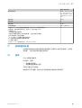
SICK PowerProx Small Analog - WTT190L-Kxxxx Instruções de operação
- Tipo
- Instruções de operação
em outras línguas
Artigos relacionados
-
SICK PowerProx Small Analog - WTT190L-Axxxx Instruções de operação
-
-
-
-
-
-
-
-
-
