Titan 0289013 Manual do usuário
- Categoria
- Pulverizador de tinta
- Tipo
- Manual do usuário

Model Numbers:
M-4 3600 PSI (250 bar), G-THD, with tip holder 0289013
M-8 7700 PSI (530 bar), G-THD, with tip holder 0289014
English ....................................... p. 2
Deutsch....................................S. 14
Français ...................................p. 26
Español ....................................p. 38
Italiano ....................................p. 50
Português ................................ p. 62
Nederlands .............................. b. 74
Dansk ....................................... s. 86
Svenska ................................... s. 98
0518 • Form No. 2347780 D
DK S
E I
GB F
D
P NL
DK S
E I
GB F
D
P NL
M-4 / M-8
High Capacity
Spray Gun
Owner’s Manual • Betriebsanleitung
Mode d’emploi • Gebruiksaanwijzing
Manuale dell’utente • Manual de usuario
Ejermanual • Användarmanual
Manual de utilização

2
M-4/M-8
GB
Safety Precautions
Be safety-conscious! All local and national regulations
governing ventilation, re prevention, and operation must be
observed.
HAZARD: Injection injury
A high pressure stream produced by this equipment can
pierce the skin and underlying tissues, leading to serious
injury and possible amputation. See a physician immediately.
DO NOT TREAT AN INJECTION INJURY AS A SIMPLE CUT! Injection can
lead to amputation. See a physician immediately. Inform the physician
of the type of coating material or cleaning agent with which the injury
was caused.
• NEVER aim the gun at any part of the body.
• NEVER allow any part of the body to touch the uid stream. DO NOT
allow body to touch a leak in the uid hose.
• NEVER put hand in front of the gun. Gloves will not provide protection
against an injection injury.
• Never point the spray gun at anyone else.
• ALWAYS lock the gun trigger, shut the pump o, and release all
pressure before servicing, cleaning the tip or guard, changing tip, or
leaving unattended. Pressure will not be released by turning o the
motor. The PRIME/SPRAY valve must be turned to PRIME to relieve the
pressure. Refer to the Pressure Relief Pressure described in the pump
manual.
• ALWAYS keep the tip guard in place while spraying. The tip guard
provides some protection but is mainly a warning device.
• ALWAYS remove the spray tip before ushing or cleaning the system.
• The paint hose can develop leaks from wear, kinking and abuse. A leak
can inject material into the skin. Inspect the hose before each use.
• NEVER use a spray gun without a trigger lock and trigger guard in place
and in good working order.
• All accessories must be rated at or above the maximum operating
pressure range of the airless sprayer. This includes spray tips,
extensions, and hose.
HAZARD: Explosion hazard due to incompatible materials
Will cause severe injury or property damage.
• Do not use materials containing bleach or chlorine.
• Do not use halogenated hydrocarbon solvents such as bleach,
mildewcide, methylene chloride and 1,1,1 - trichloroethane. They are
not compatible with aluminum.
• Contact your coating material supplier about the compatibility of
material with aluminum.

3
M-4/M-8
GB
HAZARD: General
This product can cause severe injury or property damage.
1. Read all instructions and safety precautions before operating
equipment.
2. Never spray near sources of ignition; e.g. open ames, cigarettes — also
cigars and pipes are sources of ignition —, sparks, hot wires and hot
surfaces, etc.
3. Wear respiratory equipment when spraying. The operator must be
provided with a protective mask.
In order to prevent work related illness, the manufacturer’s regulations
for the materials, solvents, and cleaning agents used must be observed
when preparing, working with and cleaning the unit. Protective
clothing, gloves, eyewear, and, in certain cases, protective skin cream
are necessary to protect the skin.
4. Follow the coating material and solvent manufacturer’s warnings and
instructions.
5. Extraction equipment should be installed by the user in accordance
with local regulations.
6. The objects being sprayed must be earthed.
7. Before each use, check all hoses for cuts, leaks, abrasion or bulging
of cover. Check for damage or movement of couplings. Immediately
replace the hose if any of these conditions exist. Never repair a paint
hose. Replace it with another grounded high-pressure hose.
8. Pulling the trigger causes a recoil force to the hand that is holding the
spray gun.
The recoil force of the spray gun is particularly powerful when the tip
has been removed and a high pressure has been set on the airless high-
pressure pump. Therefore, when cleaning without tip set the pressure
control valve to the lowest pressure.
9. Use only manufacturer authorized parts. User assumes all risks
and liabilities when using parts that do not meet the minimum
specications and safety devices of the spray gun manufacturer.

4
M-4/M-8
GB
EXPLOSION PROTECTION IDENTIFICATION
X marking:
The spray gun corresponds with Ex II 2G c IIC T6 X and is, in accordance
with Directive 2014/34 EU, suitable for use in explosion-hazardous
areas—as of type Zone 1. Under certain circumstances, the unit itself
may cause the Zone 1 condition to be in eect.
Any static-electricity discharge from the spray gun is to be diverted to
the grounded high-pressure pump via the conductive high-pressure
hose as stipulated.
The maximum surface temperature corresponds to the permissible
material temperature. This and the permissible ambient temperature
can be found in the Technical Data.
To avoid the generation of machine sparks, prevent impact stresses and any
work on the unit with tools in the explosion-hazardous area.
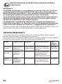
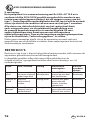
Residual risks
Residual risks are risks, which cannot be excluded, even when equipment is
used for the intended purpose.
In such cases the applicable areas of the actual residual risks will be pointed
out using warning and/or prohibition signs.
Risk Source /
Cause
Impact Preventative
measures
Can occur
during:
Injection
injury
High pressure
stream of
uid
Severe
injury or
amputation
NEVER aim the
gun at any part
of the body
Setup,
Operation
Explosion or
re
Static
electricity or
sparks
Severe injury Use well
ventilated area
Ground the
spray gun
Operation
Hazardous
vapors
Hazardous
vapors
from spray
material
Severe injury Use well
ventilated area
Use respiratory
Operation

5
M-4/M-8
GB
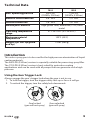
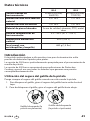
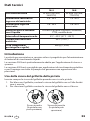
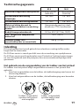
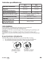
Technical Data
M-4 M-8
Max. operating pressure 3600 PSI
(25 MPa, 250 bar)
7700 PSI
(53 MPa, 530 bar)
Material inlet thread size 3/8” NPS 1/4” NPS
Diuser thread size 7/8” NPS 7/8” NPS
Wetted parts material High-grade steel, aluminum, PTFE, hard
metal
Operating temperature
range
41°F to 104°F (5ºC to 40ºC)
Maximum material
temperature
109°F (43ºC)
Weight (cpl. incl. tip guard
and tip)
1.5 lbs (680 g)
Introduction
This airless spray gun is to be used for the high pressure atomization of liquid
coating materials.
The 3600 PSI (250 bar) version is especially suitable for processing spray ller.
The 7700 PSI (530 bar) version is best suited for protective coating
applications and can be used with all pumps that can generate such a high
pressure.
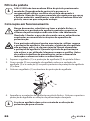
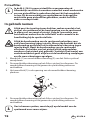
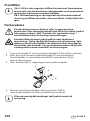
Using the Gun Trigger Lock
Always engage the gun’s trigger lock when the gun is not in use.
1. To lock the trigger, turn the trigger safety lock up as far as it will go.
2. To unlock the trigger, turn the safety lock downwards.
12
Gun locked
(gun will not spray)
Gun unlocked
(gun will spray)

6
M-4/M-8
GB
Gun lter
i
The M-4 / M-8 does not include a pre-mounted gun lter.
Depending on the type of material being processed, we
recommend using the appropriate gun lter.
Attention: When processing spray ller and similar materials,
do not use a gun lter as the lter can otherwise become
blocked.
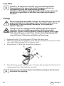
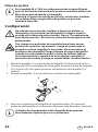
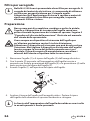
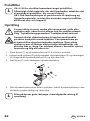
Setup
Never attempt to assemble, change, or clean the gun, tip, or tip
guard without rst relieving pressure from the spray system.
Follow the “Pressure Relief Procedure” in the sprayer’s
Owner’s Manual.
Always use a tip safety guard for added protection against
injection. Beware that the guard alone will not prevent
injection. Never cut o tip guard! Always engage gun trigger
lock when the gun is not in use. Before servicing equipment,
consult Owner’s Manuals and follow all warnings.
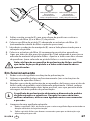
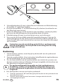
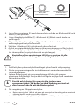
1. Remove the tip (1) and tip guard (2) from the spray gun.
2. With the tip (9) of the tip knob, insert the tip seal (3) and seal (4) into the
rear side of the tip guard (2) and press hard.
3. Insert the tip (1) into the slot on the tip guard.
1
2
3
4
9
4. Thread the tip guard onto the gun. Position the tip guard in the desired
spraying position, then tighten securely.
i
The arrow on the tip handle should be pointing in the forward
direction for spraying.

7
M-4/M-8
GB
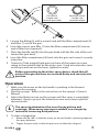
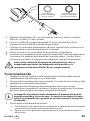
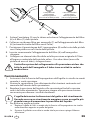
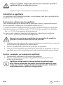
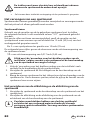
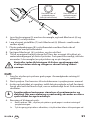
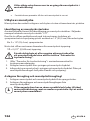
5
6
7
8
Flat side of
handle seal
(toward gun head)
Bev
elled side of
handle seal
(toward handle)
5. Loosen the tting (5) with a wrench and pull the lter compartment (6)
and lter (7) out of the gun.
6. Insert the correct gun lter (7) into the lter compartment (6) (narrow
end of lter faces upwards).
7. Place the handle seal (8) into the gun head with the at side of the seal
toward the gun head.
8. Insert the lter compartment (6) back into the gun and screw it securely
into place.
9. Connect a Titan original high-pressure hose of the proper pressure
rating to the material inlet on the airless gun. Using two wrenches (one
on the gun and one on the hose), tighten securely.
Before connecting to the airless spray device, check that all
parts of the gun and hose are screwed rmly and securely into
position.
Operation
1. Make sure the arrow on the tip handle is pointing in the forward
direction for spraying.
2. Start the sprayer. Refer to the instructions in the sprayer’s Owner’s
Manual.
3. Adjust the uid pressure on the sprayer until the spray is completely
atomized. Always spray at the lowest pressure necessary to get the
desired results.
i
The spray tip determines the size of spray pattern and
coverage. When more coverage is needed, use a larger tip
instead of increasing uid pressure.
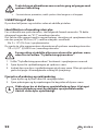
4. To clear a clogged tip:
a. Rotate the tip 180º so that the arrow on the tip handle is pointing opposite
the spray direction.
b. Trigger the gun once so that the pressure can blow the clog out.

8
M-4/M-8
GB
Attention
Never pull the trigger more than once at time with the tip in
the reverse position.
c. Continue this procedure until the tip is clear of the clog.
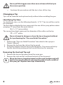
Changing a Tip
Tips can be removed and replaced easily without disassembling the gun.
Identifying Tip Sizes
To identify tip sizes, use the following formula. A “517” tip size will be used in
this example.
The rst digit multiplied by two represents the size of the spray pattern when
spraying 12” away from the work surface:
5 x 2 = 10” spray pattern
The second two digits represent the diameter of the orice on the tip:
17 = .017” orice
Never attempt to change or clean the tip or tip guard without
rst performing the “Pressure Relief Procedure.”
1. Perform the “Pressure Relief Procedure” described in the sprayer’s
Owner’s Manual.
2. Remove the tip from the slot on the tip guard.
3. Insert the new tip into the slot on the tip guard. The arrow on the tip
handle should be pointing in the forward direction for spraying.
Removing the Seal and Tip seal
1. Remove the tip and tip guard from the spray gun.
2. Remove the seal and tip seal from the back of the tip guard.
i
Worn tips have a negative impact on the spray pattern and will
lead to increased material consumption and a smaller width of
the spray jet. Replace worn tips immediately.

9
M-4/M-8
GB
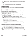
Cleanup
A well-cleaned airless gun is essential for a satisfactory level of operational
quality. Flush the gun after each use and store in a dry location. Do not leave
the gun or any of its parts in water or solvents.
Special cleanup instructions for use with ammable solvents:
• Always ush spray gun preferably outside and at least one hose length
from spray pump.
• If collecting ushed solvents in a 1 gallon (4 litre ) metal container, place
it into an empty 5 gallon (20 litre) container, then ush solvents.
• Area must be free of ammable vapors and well ventilated.
• Follow all cleanup instructions.
At
tention
The spray device, the hose and the airless gun have to be
cleaned thoroughly after using, as otherwise the paint
that was used can accumulate and considerably impair the
performance of the device.
Always spray at the lowest possible pressure when the tip and
tip guard have been removed. To clean the airless gun, hose
and spray device, use only water or a suitable solvent.

10
M-4/M-8
GB
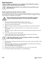
Maintenance
Follow all safety precautions as described in the Safety Precautions
section of this manual before proceeding.
i
Refer to the Spare Parts List section in this manual for part
identication.
Replacing/Servicing the Seal Assembly
If any material leaks from the spray gun when the trigger is not activated,
then either the needle or the needle seat could be worn, damaged or dirty
and need to be cleaned or replaced.
Never attempt to perform maintenance on the spray gun
without rst performing the “Pressure Relief Procedure.”
1. Disconnect the material hose from the airless gun.
For the next steps, please refer to the picture on page 11.
2. Remove the tip and tip guard.
3. With the trigger depressed, remove the diuser from the front of the
gun.
4. Unscrew the cap (1) with a at head screw driver, then remove the
spring (2).
5. With the 10-mm socket wrench, loosen the needle (3) and pull it out of
the gun.
6. Clean the removed parts thoroughly.
7. Inspect the parts for wear or damage and use new parts during
reassembly of the gun, when necessary.
i
Lubricate all packings and moving parts before reassembly
with a lithium-based grease.
8. Slide the rear housing onto the retractor pins and secure in position with
the lock nut.
10. WIth the trigger depressed, install the diuser into the front of the gun
head and tighten securely with a wrench.
11. Insert the needle back into the gun.
12. Replace the spring (2) and tighten the cap (1) as far as the stop.
13. If required, adjust the packing as described below.

11
M-4/M-8
GB
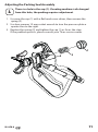
Adjusting the Packing Seal Assembly
i
There is a hole in the cap (1). If coating medium is discharged
from this hole, the packing requires adjustment
1. Unscrew the cap (1) with a at head screw driver, then remove the
spring (2).
2. Use box spanner 10 mm socket wrench to turn the pressure plate a
quarter turn to the right.
3. Replace the spring (2) and tighten the cap (1) as far as the stop.
If the problem persists, please consult your Titan service center.
1
2
3

12
M-4/M-8
GB
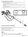
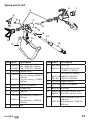
Replacing/Removing the Filter
1. Loosen the tting (1) with a wrench and pull the lter housing (2) and
lter (3) out of the gun.
2. Take the old lter out of the lter housing.
3. Insert the new lter, with the narrow end facing upwards, into the lter
housing.
4. Place the handle seal into the gun head with the at side of the seal
toward the gun head.
5. Insert the lter housing (3) back into the gun and screw it securely into
place.
1
2
3
4
Flat side of
handle seal
(toward gun head)
Bev
elled side of
handle seal
(toward handle)
EU Declaration of conformity
We declare under sole responsibility that this product conforms to the
following relevant stipulations:
2006/42/EC, 2014/34/EU, 2011/65/EU
Applied harmonised norms:
EN ISO 12100, EN 1953, EN ISO 80079-36
II 2G X
The EU declaration of conformity is enclosed with the product.
If required, it can be re-ordered using order number 2389342.

13
M-4/M-8
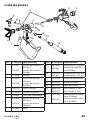
GB
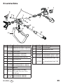
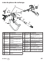
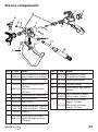
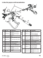
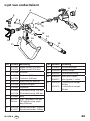
12
3
4
5
6
6
7
8
9
10
11
12
13
14
15
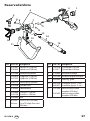
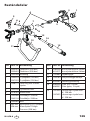
Item Part # Description
1 0335301
2339659
Cap (3600 PSI,
250 bar)
Cap (7700 PSI, 530 bar)
2 2332588 Handle recess
3 2344878
0347335
Pressure spring (3600PSI,
250 bar)
Pressure spring (7700PSI,
530 bar)
4 2348175 Seal Assy/Diuser
5 2332598 Cylinder pin
6 9910403 Cap nut
7 2343066
2343158
Gun housing (3600 PSI,
250 bar)
Gun housing (7700 PSI,
530 bar)
8 2343085 Bolt
Item Part # Description
9 662-xxx
696-xxx
SC6+Tip
TR High Pressure tip
(7700 PSI, 530 bar)
10
0289228
661-027
Tip guard (G thread)
3600 PSI
(250 bar)
7700 PSI (530 bar)
11 2332605 Trigger guard
12 2333189 Trigger, complete
13 0043303 Grip seal
14 0089958
0089957
Gun lter (white, 2 pc.)
Gun lter (green, 2 pc.)
15 2347490
2347492
Filterhousing (3600 PSI,
250 bar)
Filterhousing (7700 PSI,
530 bar)
Spare parts list

14
M-4/M-8
D
Sicherheitshinweise
Sicherheit ist oberstes Gebot! Es müssen alle lokalen und
nationalen Vorschriften zur Entlüftung, zum Brandschutz und
zum Arbeitsschutz eingehalten werden.
GEFAHR: Verletzung durch Flüssigkeiten unter Druck
Der durch dieses Gerät erzeugte Hochdrucküssigkeitsstrahl
kann Haut und Bindegewebe durchdringen und schwere
Verletzungen verursachen, die sogar zur Amputation führen
können. Sofort einen Arzt aufsuchen.
EINE VERLETZUNG DURCH EINE INJEKTION VON FLÜSSIGKEIT UNTER
DRUCK NICHT WIE EINEN NORMALEN SCHNITT BEHANDELN! Eindringen
von Flüssigkeiten unter Druck in das Gewebe können Amputationen
erforderlich machen. Sofort einen Arzt aufsuchen. Der Arzt muss über
die Art des Überzugs oder Reinigungsmittels informiert werden, der
bzw. das die Verletzung verursacht hat.
• NIEMALS die Airless Pistole auf Körperteile richten.
• NIEMALS mit Körperteilen in den Flüssigkeitsstrahl kommen. NIEMALS
mit dem Körper eine Leckstelle im Druckschlauch berühren.
• NIEMALS die Hand vor die Düse der Airless Pistole halten. Handschuhe
stellen keinen sicheren Schutz vor Verletzungen durch injizierte
Flüssigkeiten dar.
• NIEMALS die Airless Pistole auf Personen richten.
• STETS den Abzug der Airless Pistole verriegeln, die Pumpe ausschalten
und den Druck vollständig entlasten, bevor Wartungs- und
Reinigungsarbeiten an Düse und Düsenschutz oder Düsenwechsel
durchgeführt werden oder das Gerät unbeaufsichtigt gelassen wird.
Auch nach dem Ausschalten des Motors steht das Gerät noch unter
Druck. Das Ventil PRIME/SPRAY (Vorfüllen/Sprühen) muss auf PRIME
(Vorfüllen) gestellt sein, um den Druck zu entlasten. Der Ansprechdruck
für das Ventil ist im Pumpenhandbuch angegeben.
• STETS den Düsenschutz beim Sprühen aufsetzen. Der Düsenschutz
stellt einen gewissen Schutz dar, ist aber vor allem als Warnvorrichtung
gedacht.
• STETS die Spritzdüse entfernen, bevor das System gereinigt oder
gespült wird.
• Der Farbschlauch kann durch falsche Verwendung, Knicken und durch
Verschleiß undicht werden. Durch eine Leckstelle kann Flüssigkeit in die
Haut injiziert werden. Vor Verwendung den Schlauch gründlich prüfen.
• NIEMALS eine Airless Pistole ohne Abzugsicherung und
funktionsfähigen Abzugbügel verwenden.
• Das gesamte Zubehör muss mindestens für den maximalen
Betriebsdruck des Airless-Spritzgeräts zugelassen sein. Dies betrit
Spritzdüsen, Verlängerungen und den Schlauch.

15
M-4/M-8
D
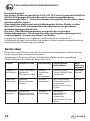
GEFAHR: Explosionsgefahr aufgrund inkompatibler Materialien
Inkompatible Materialien können schwere Personen- und
Sachschäden verursachen.
• Keine Materialien verarbeiten, die Chlor oder Hypochlorid enthalten.
• Keine halogenierten Kohlenwasserstoe als Lösungsmittel verwenden,
beispielsweise Hypochloridlösung, Schimmelbekämpfungsmittel,
Methylenchlorid und 1,1,1-Trichlorethan. Diese Lösungsmittel greifen
Aluminium an.
• Informationen zur Verträglichkeit des verwendeten
Beschichtungsmaterials mit Aluminium erhalten Sie vom Hersteller.
GEFAHR: Allgemeines
Kann schwere Personen- oder Sachschäden verursachen.
1. Alle Anweisungen und Sicherheitshinweise durcharbeiten, bevor das
Gerät in Betrieb genommen wird.
2. Niemals in der Nähe von Zündquellen sprühen, d. h. nicht in der Nähe
von oenen Flammen, Zigaretten (auch Zigarren und Pfeifen sind
Zündquellen), Funken, heißen Drähten, heißen Oberächen usw.
3. Beim Sprühen Atemschutz tragen. Der Bediener muss eine Schutzmaske
tragen. Um arbeitsbedingte Erkrankungen zu vermeiden, die
Vorschriften des Herstellers zu den Farben bzw. Lacken, Lösungsmitteln
und Reinigungsmitteln beachten, wenn das Gerät vorbereitet, benutzt
und gereinigt wird. Schutzkleidung, Arbeitshandschuhe, Augenschutz
und in bestimmten Fällen eine besondere Hautschutzcreme verwenden.
4. Die Warnhinweise und Anweisungen des Herstellers von Farbe bzw.
Lack und Lösungsmittel beachten.
5. Die Absaugvorrichtungen müssen vom Benutzer entsprechend den vor
Ort geltenden Vorschriften angeschlossen werden.
6. Die für die Beschichtung vorgesehenen Gegenstände müssen geerdet
sein.
7. Vor jedem Einsatz alle Schläuche auf Schnitt-, Leck- und Scheuerstellen
sowie auf Verformungen des Schlauchmantels kontrollieren. Die
Kupplungen auf Unversehrtheit und festen Sitz kontrollieren. Den
Schlauch sofort ersetzen, wenn einer der erwähnten Fehler festgestellt
wird. Einen Farbschlauch niemals reparieren. In diesem Fall den
Schlauch durch einen anderen geerdeten Hochdruckschlauch ersetzen.
8. Bei Betätigung des Abzugs zieht die Airless Pistole zur Seite. Diese
Kraftwirkung der Airless Pistole ist besonders stark, wenn die Düse
entfernt wurde und bei der Hochdruckpumpe hoher Druck eingestellt
wurde. Bei der Reinigung mit abgeschraubter Düse daher das
Druckregelventil auf den niedrigsten Druck einstellen.
9. Nur vom Hersteller zugelassene Teile verwenden. Der Benutzer trägt alle
Risiken und das gesamte Haftungsrisiko bei Verwendung von Teilen,
die nicht die technischen Mindestdaten erfüllen, sowie bei Verwendung
von Sicherheitsvorrichtungen, die nicht vom Hersteller der Airless
Pistole stammen.

16
M-4/M-8
D
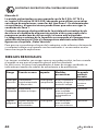
EXPLOSIONSSCHUTZ KENNZEICHNUNG
Kennzeichnung X:
Die Airless Pistole entspricht Ex II 2G c IIC T6 X und ist nach der Richtlinie
2014/34 EU geeignet für den Einsatz in explosionsgefährdeten
Bereichen der Zone 1. Unter Umständen erzeugt das Gerät selbst schon
den Bereich der Zone 1.
Eine mögliche elektrostatische Auadung der Airless Pistole ist über
den nach Vorschrift leitenden Hochdruckschlauch zur geerdeten
Hochdruckpumpe abzuleiten.
Die max. Oberächentemperatur entspricht der zulässigen
Materialtemperatur. Diese und die zulässige Umgebungstemperatur
sind im Kapitel „Technische Daten“ zu nden.
Um die Entstehung von Funken an der Maschine zu verhindern,
Schlagbelastungen vermeiden und an dem Gerät in explosionsgefährdeten
Bereichen keine Werkzeuge einsetzen.
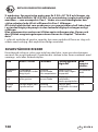
Restrisiken
Restrisiken sind Risiken, die auch bei bestimmungsgemässer Verwendung
nicht ausgeschlossen werden können.
Gegebenenfalls weisen Warn- und Verbotsschilder an den jeweiligen
Risikostellen auf bestehende Restrisiken hin.
Gefahr Quelle/Ursache Auswirkung Vorbeugende
Maßnahmen
Kann
auftreten
während:
Injektions-
verletzung
Unter Hochdruck
stehender
Flüssigkeitsstrom
Schwere
Verletzung
oder
Amputation
Richten Sie die
Pistole NIEMALS auf
Körperteile
Montage,
Betrieb
Explosion
oder Feuer
Statische
Elektrizität oder
Funken
Schwere
Verletzung
Nur in gut durch-
lüfteten Bereichen
verwenden
Erden Sie die Airless
Pistole
Betrieb
Gefährliche
Dämpfe
Gefährliche
Dämpfe aus den
Spritzmaterialien
Schwere
Verletzung
Nur in gut
durchlüfteten
Bereichen
verwenden
Verwenden Sie eine
Maske
Betrieb

17
M-4/M-8
D
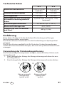
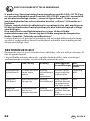
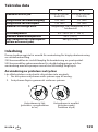
Technische Daten
M-4 M-8
Maximaler Betriebsdruck 25 MPa (250 bar,
3600 PSI)
53 MPa (530 bar,
7700 PSI)
Gewinde Materialeingang 3/8” NPS 1/4” NPS
Diusergewinde 7/8” NPS 7/8” NPS
Werkstoe der Teile, die Kontakt
mit dem Beschichtungsmaterial
haben
Qualitätsstahl, Aluminium, PTFE,
Hartmetall
Betriebstemperaturbereich 5ºC bis 40ºC (41°F -104°F)
Maximale Farbtemperatur 43ºC (109°F)
Gewicht (kpl. inkl. Düsenhalter
und Düse)
680 g (1,5 lbs)
Einführung
Diese Airless Pistole ist für die Hochdruck-Zerstäubung von üssigen
Beschichtungsstoen vorgesehen.
Die 250 bar Version ist besonders für die Verarbeitung von Spritzspachtel
geeignet.
Die 530 bar Version empehlt sich für Protective Coating Anwendungen
und für den Einsatz mit allen Pumpen, die einen entsprechend hohen Druck
erzeugen.
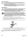
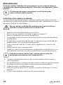
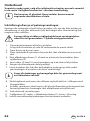
Verwendung der Pistolenabzugsicherung
Die Pistolenabzugsicherung immer einlegen, wenn die Airless Pistole nicht
verwendet wird.
1. Zum Verriegeln des Abzugs die Abzugssicherung nach oben bis zum
Anschlag drehen.
2. Zum Entriegeln des Abzugs die Abzugssicherung nach unten drehen.
12
Abzug verriegelt
(Spritzpistole
sprüht nicht)
Abzug entriegelt
(Spritzpistole
sprüht)

18
M-4/M-8
D
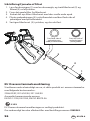
Pistolenlter
i
In der M-4 / M-8 ist kein Pistolenlter vormontiert. Abhängig
vom zu verarbeitenden Material ist es empfehlenswert, einen
der Düse entsprechenden Pistolenlter zu verwenden.
Achtung: Bei der Verarbeitung von Spritzspachtel und
ähnlichen Materialien keinen Pistolenlter verwenden, da der
Filter ansonsten verstopft.
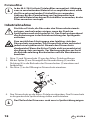
Inbetriebnahme
Die Airless Pistole, die Düse oder den Düsenschutz niemals
zerlegen, wechseln oder reinigen, wenn der Druck im
Spritzsystem noch nicht entastet ist. Den Druck entsprechend
den Anweisungen in der Betriebsanleitung des Spritzgeräts
entlasten.
Zum zusätzlichen Schutz gegen eine Injektion stets den
Düsenschutz verwenden. Der Düsenschutz allein verhindert
jedoch eine Injektion nicht. Niemals den Düsenschutz
abschneiden! Wenn die Airless Pistole nicht verwendet wird,
den Abzug stets verriegeln. Vor Wartungsarbeiten am Gerät
die Betriebsanleitung durcharbeiten und alle Warnhinweise
beachten.
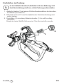
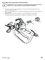
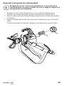
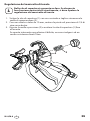
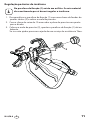
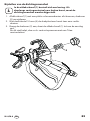
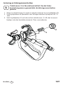
1. Düse (1) und Düsenschutz (2) von der Airless Pistole entfernen.
2. Mit der Spitze (9) am Düsengri die Düsendichtung (3) und die
Dichtung (4) in die Rückseite des Düsenschutzes (2) einsetzen und
festdrücken.
3. Die Düse (1) in die Önung im Düsenschutz einsetzen.
1
2
3
4
9
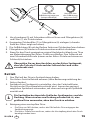
4. Den Düsenschutz an die Airless Pistole einschrauben. Den Düsenschutz
in die gewünschte Sprührichtung stellen und festziehen.
i
Der Pfeil auf der Düse muss nach vorn in Sprührichtung zeigen.

19
M-4/M-8
D
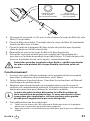
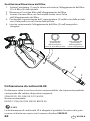
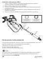
5
6
7
8
Flache Seite der
Gri
dichtung (zeigt zum
Spritzpistolenkopf)
Konische Seite
der Gri
dichtung
(zeigt zum Gri)
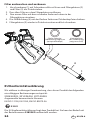
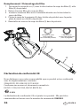
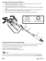
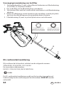
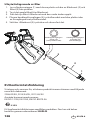
5. Verschraubung (5) mit Schraubenschlüssel lösen und Filtergehäuse (6)
und Filter (7) aus Pistole ziehen.
6. Geeigneten Pistolenlter (7) in Filtergehäuse (6) einlegen (schmales
Ende des Filters zeigt nach oben).
7. Die Gridichtung (8) mit der achen Seite zum Pistolenkopf einschieben.
8. Filtergehäuse (6) wieder in Pistole einsetzen und festschrauben.
9. Einen für den Druck geeigneten original Hochdruckschlauch von Titan
am Materialeingang der Airless Pistole anschließen. Den Schlauch mit
zwei Schraubenschlüsseln (einem an der Airless Pistole und einem am
Schlauch) festziehen.
Überprüfen Sie vor dem Anschluss an das Airless Spritzgerät,
dass alle Teile der Pistole und der Schlauch fest und sicher
verschraubt sind.
Betrieb
1. Den Pfeil auf der Düse in Spritzrichtung drehen.
2. Das Airless-Gerät in Betrieb nehmen (siehe Bedienungsanleitung des
Airless-Gerätes).
3. Spritzdruck am Spritzgerät so einstellen, dass der Farbstrahl beim
Austritt an der Düse komplett zerstäubt wird. Immer den geringst
möglichen Spritzdruck verwenden, mit dem noch ein gutes Spritzbild
erreicht wird.
i
Die Spritzdüse bestimmt die Größe des Sprühmusters und die
Deckung. Wenn eine bessere Deckung erforderlich ist, eine
größere Düse verwenden, ohne den Druck zu erhöhen.
4. Reinigung einer verstopften Düse:
a. Die Düse um 180° drehen, sodass der Pfeil auf der Düse entgegen der
Sprührichtung zeigt.
b. Die Airless Pistole kurz auslösen, sodass die Verstopfung durch den Druck
beseitigt werden kann.

20
M-4/M-8
D
Achtung
Den Abzug immer nur kurz betätigen, wenn die Düse in der
verkehrten Richtung steht.
c. Diesen Schritt wiederholen, bis die Verstopfung der Düse beseitigt ist.
Düse wechseln
Düsen können bequem entfernt und ersetzt werden, ohne dass die Airless
Pistole zerlegt werden muss.
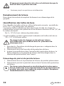
Düsengröße bestimmen
Zur Bestimmung der Düsengröße dient folgende Formel: Bei diesem Beispiel
wird eine Düsengröße 517 verwendet.
Die erste Zier multipliziert mit 2 entspricht der Größe des Sprühbildes in
einem Abstand von 12” (30,5 cm) von der Arbeitsäche:
5 x 2 = 10” (25,4 cm) Sprühbild
Die beiden anderen Ziern geben den Durchmesser der Düsenönung an:
17 = 0,017” (0,043 mm) Düsenönung
Niemals die Düse oder den Düsenschutz wechseln oder
reinigen, wenn das System noch unter Druck steht.
1. Den Druck entsprechend den Anweisungen in der Betriebsanleitung
des Spritzgeräts entlasten.
2. Die Düse aus dem Schlitz des Düsenschutzes entfernen.
3. Die neue Düse in den Schlitz am Düsenschutz einsetzen. Der Pfeil an der
Düse muss nach vorn in Sprührichtung zeigen.
Dichtung und Düsendichtung entfernen
1. Düse und Düsenschutz von der Airless Pistole abbauen.
2. Dichtung und Düsendichtung von der Rückseite des Düsenschutzes
entfernen.
i
Verschlissene Düsen haben ein schlechteres Spritzbild und
führen zu einem erhöhten Materialverbrauch sowie einer
geringeren Sprühstrahlbreite. Verschlissene Düsen sofort
ersetzen.
A página está carregando...
A página está carregando...
A página está carregando...
A página está carregando...
A página está carregando...
A página está carregando...
A página está carregando...
A página está carregando...
A página está carregando...
A página está carregando...
A página está carregando...
A página está carregando...
A página está carregando...
A página está carregando...
A página está carregando...
A página está carregando...
A página está carregando...
A página está carregando...
A página está carregando...
A página está carregando...
A página está carregando...
A página está carregando...
A página está carregando...
A página está carregando...
A página está carregando...
A página está carregando...
A página está carregando...
A página está carregando...
A página está carregando...
A página está carregando...
A página está carregando...
A página está carregando...
A página está carregando...
A página está carregando...
A página está carregando...
A página está carregando...
A página está carregando...
A página está carregando...
A página está carregando...
A página está carregando...
A página está carregando...
A página está carregando...
A página está carregando...
A página está carregando...
A página está carregando...
A página está carregando...
A página está carregando...
A página está carregando...
A página está carregando...
A página está carregando...
A página está carregando...
A página está carregando...
A página está carregando...
A página está carregando...
A página está carregando...
A página está carregando...
A página está carregando...
A página está carregando...
A página está carregando...
A página está carregando...
A página está carregando...
A página está carregando...
A página está carregando...
A página está carregando...
A página está carregando...
A página está carregando...
A página está carregando...
A página está carregando...
A página está carregando...
A página está carregando...
A página está carregando...
A página está carregando...
A página está carregando...
A página está carregando...
A página está carregando...
A página está carregando...
A página está carregando...
A página está carregando...
A página está carregando...
A página está carregando...
A página está carregando...
A página está carregando...
A página está carregando...
A página está carregando...
A página está carregando...
A página está carregando...
A página está carregando...
A página está carregando...
A página está carregando...
A página está carregando...
A página está carregando...
A página está carregando...
A página está carregando...
A página está carregando...
A página está carregando...
A página está carregando...
A página está carregando...
A página está carregando...
A página está carregando...
A página está carregando...
-
 1
1
-
 2
2
-
 3
3
-
 4
4
-
 5
5
-
 6
6
-
 7
7
-
 8
8
-
 9
9
-
 10
10
-
 11
11
-
 12
12
-
 13
13
-
 14
14
-
 15
15
-
 16
16
-
 17
17
-
 18
18
-
 19
19
-
 20
20
-
 21
21
-
 22
22
-
 23
23
-
 24
24
-
 25
25
-
 26
26
-
 27
27
-
 28
28
-
 29
29
-
 30
30
-
 31
31
-
 32
32
-
 33
33
-
 34
34
-
 35
35
-
 36
36
-
 37
37
-
 38
38
-
 39
39
-
 40
40
-
 41
41
-
 42
42
-
 43
43
-
 44
44
-
 45
45
-
 46
46
-
 47
47
-
 48
48
-
 49
49
-
 50
50
-
 51
51
-
 52
52
-
 53
53
-
 54
54
-
 55
55
-
 56
56
-
 57
57
-
 58
58
-
 59
59
-
 60
60
-
 61
61
-
 62
62
-
 63
63
-
 64
64
-
 65
65
-
 66
66
-
 67
67
-
 68
68
-
 69
69
-
 70
70
-
 71
71
-
 72
72
-
 73
73
-
 74
74
-
 75
75
-
 76
76
-
 77
77
-
 78
78
-
 79
79
-
 80
80
-
 81
81
-
 82
82
-
 83
83
-
 84
84
-
 85
85
-
 86
86
-
 87
87
-
 88
88
-
 89
89
-
 90
90
-
 91
91
-
 92
92
-
 93
93
-
 94
94
-
 95
95
-
 96
96
-
 97
97
-
 98
98
-
 99
99
-
 100
100
-
 101
101
-
 102
102
-
 103
103
-
 104
104
-
 105
105
-
 106
106
-
 107
107
-
 108
108
-
 109
109
-
 110
110
-
 111
111
-
 112
112
-
 113
113
-
 114
114
-
 115
115
-
 116
116
-
 117
117
-
 118
118
-
 119
119
-
 120
120


Titan 0289013 Manual do usuário
- Categoria
- Pulverizador de tinta
- Tipo
- Manual do usuário
em outras línguas
- español: Titan 0289013 Manual de usuario
- français: Titan 0289013 Manuel utilisateur
- italiano: Titan 0289013 Manuale utente
- Nederlands: Titan 0289013 Handleiding
- dansk: Titan 0289013 Brugermanual
Artigos relacionados
-
Titan RX-Pro Airless Spray Gun Manual do usuário
-
-
-
-
-
-
Titan Impact 1040 Instruções de operação
Outros documentos
-
WAGNER Control Pro Airless Spray Gun Manual do proprietário
-
WAGNER 0418B Manual do usuário
-
GYS Magnetic earth Ficha de dados
-
3M Accuspray™ ONE Spray Gun Kit Instruções de operação
-
Graco 309642H CleanShot Shut-off Valve Manual do proprietário
-
Paasche 2000SI Manual do usuário
-
Sagola Classic Lisos Manual do usuário
-
-
Hans Grohe AXOR Montreux 16546 Series Manual do usuário