Titan Impact 1040 Instruções de operação
- Categoria
- Limpadores de alta pressão
- Tipo
- Instruções de operação

MODEL
0532047
0532048
IMPACT 1040
0617 • Form No. 0532899A
AIRLESS, HIGH-PRESSURE
SPRAYING UNIT
AIRLESS EQUIPO DE ALTA
PRESIÓN PARA PULVERIZAR
UNIDADE DE PULVERIZAÇÃO
SEM AR E DE ALTA PRESSÃO
- E - INSTRUCCIONES DE USO 30
- RFB - MANUAL DE OPERAÇÕES 58
OPERATING MANUAL

2
original operating manual
Impact 1040
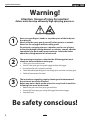
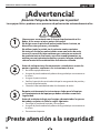
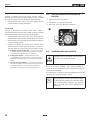
Warning!
Attention: Danger of injury by injection!
Airless units develop extremely high spraying pressures.
Be safety conscious!
1
2
3
Never put your ngers, hands or any other parts of the body into
the spray jet!
Never point the spray gun at yourself, other persons or animals.
Never use the spray gun without safety guard.
Do not treat a spraying injury as a harmless cut. In case of injury
to the skin through coating materials or solvents, consult a doctor
immediately for quick and expert treatment. Inform the doctor
about the coating material or solvent used.
The operating instructions state that the following points must
always be observed before starting up:
1. Faulty units must not be used.
2. Secure Titan spray gun using the trigger lock on the trigger.
3. Ensure that the unit is properly earthed.
4. Check allowable operating pressure of high-pressure hose and spray gun.
5. Check all connections for leaks.
The instructions regarding regular cleaning and maintenance of
the unit must be strictly observed.
Before any work is done on the unit or for every break in work the
following rules must be observed:
1. Release the pressure from spray gun and hose.
2. Secure the Titan spray gun using the trigger lock on the trigger.
3. Switch o unit.

3
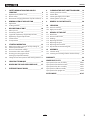
contents
Impact 1040
1 SAFETY REGULATIONS FOR AIRLESS
SPRAYING ______________________________ 4
1.1 Explanation of symbols used _____________________4
1.2 Electric safety _________________________________8
1.3 Electrostatic charging (formation of sparks or ames) 8
2 GENERAL VIEW OF APPLICATION __________ 9
2.1 Application ___________________________________ 9
2.2 Coating materials ______________________________ 9
3 DESCRIPTION OF UNIT __________________ 10
3.1 Airless process _______________________________10
3.2 Functioning of the unit ________________________10
3.3 Legend for explanatory diagram Impact 1040 ______10
3.4 Explanatory diagram Impact 1040 _______________11
3.5 Technical data _______________________________12
3.6 Transportation _______________________________12
4 STARTING OPERATION __________________ 13
4.1 High-pressure hose, spray gun and separating oil ___ 13
4.2 Control panel indicators _______________________13
4.3 Pressure control knob settings __________________14
4.4 Connection to the mains network _______________14
4.5 Cleaning preserving agent when
starting-up of operation initially _________________15
4.6 Taking the unit into operation with coating material 15
5 SPRAYING TECHNIQUE __________________ 16
6 HANDLING THE HIGHPRESSURE HOSE ____ 17
7 INTERRUPTION OF WORK ________________ 17
8 CLEANING THE UNIT SHUTTING DOWN __ 18
8.1 Cleaning unit from outside _____________________18
8.2 Suction lter _________________________________18
8.3 Cleaning the high-pressure lter ________________19
8.4 Cleaning Airless spray gun _____________________19
9 REMEDY IN CASE OF FAULTS _____________ 20
10 SERVICING _____________________________ 21
10.1 General servicing _____________________________21
10.2 High-pressure hose ___________________________21
11 REPAIRS AT THE UNIT ___________________ 21
11.1 Relief valve __________________________________21
11.2 Inlet and outlet valve __________________________22
11.3 Packings ____________________________________23
11.4 Replacing the motor __________________________25
11.5 Replacing the gears ___________________________26
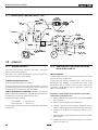
11.6 Replacing the transducer ______________________26
11.7 Impact 1040 connection diagram ________________28
12 APPENDIX _____________________________ 28
12.1 Selection of tip _______________________________28
12.2 Servicing and cleaning of Airless hard-metal tips ___28
WARRANTY _________________________________ 29
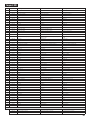
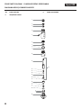
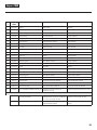
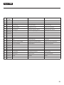
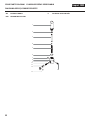
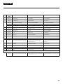
SPARE PARTS LISTS __________________________ 86
Spare parts list for main assembly __________________ 86/87
Spare parts list for the uid section _________________ 88/89
Spare parts list for drive assembly _________________ 90/91
Spare parts list of lter assembly ___________________ 92/93
Spare parts list for upright cart ____________________ 94/95
ACCESSORIES ____________________________ 96/97

4
safety precautions
Impact 1040
1 SAFETY REGULATIONS FOR
AIRLESS SPRAYING
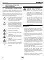
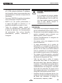
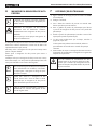
1.1 EXPLANATION OF SYMBOLS USED
This manual contains information that must be
read and understood before using the equipment.
When you come to an area that has one of the
following symbols, pay particular attention and
make certain to heed the safeguard.
This symbol indicates a potential
hazard that may cause serious
injury or loss of life. Important
safety information will follow.
This symbol indicates a potential
hazard to you or to the equipment.
Important information that tells
how to prevent damage to the
equipment or how to avoid causes
of minor injuries will follow.
Danger of skin injection
Danger of re from solvent and
paint fumes
Danger of explosion from solvent,
paint fumes and incompatible
materials
Danger of injury from inhalation
of harmful vapors
i
Notes give important information
which should be given special
attention.
HAZARD: INJECTION INJURY
Attention: Danger of injury by
injection! A high pressure stream
produced by this equipment can
pierce the skin and underlying tissues,
leading to serious injury and possible
amputation.
Do not treat a spraying injury as a
harmless cut. In case of injury to the
skin through coating materials or
solvents, consult a doctor immediately
for quick and expert treatment. Inform
the doctor about the coating material
or solvent used.
PREVENTION:
• NEVER aim the gun at any part of the body.
• NEVER allow any part of the body to touch
the uid stream. DO NOT allow body to touch
a leak in the uid hose.
• NEVER put your hand in front of the gun.
Gloves will not provide protection against an
injection injury.
• ALWAYS lock the gun trigger, shut the uid
pump o and release all pressure before
servicing, cleaning the tip guard, changing
tips, or leaving unattended. Pressure will not
be released by turning o the engine. The
PRIME/SPRAY valve or pressure bleed valve
must be turned to their appropriate positions
to relieve system pressure.
• ALWAYS keep tip guard in place while
spraying. The tip guard provides some
protection but is mainly a warning device.
• ALWAYS remove the spray tip before ushing
or cleaning the system.
• NEVER use a spray gun without a working
trigger lock and trigger guard in place.

5
safety precautions
Impact 1040
• All accessories must be rated at or above
the maximum operating pressure range of
the sprayer. This includes spray tips, guns,
extensions, and hose.
HAZARD: HIGH PRESSURE
HOSE
The paint hose can develop leaks from
wear, kinking and abuse. A leak can
inject material into the skin. Inspect
the hose before each use.
PREVENTION:
• Avoid sharp bending or kinking of the high-
pressure hose. The smallest bending radius
amounts to about 20 cm.
• Do not drive over the high-pressure hose.
Protect against sharp objects and edges.
• Replace any damaged high-pressure hose
immediately.
• Never repair defective high-pressure hoses
yourself!
• Electrostatic charging of spray guns and the
high-pressure hose is discharged through
the high-pressure hose. For this reason the
electric resistance between the connections
of the high-pressure hose must be equal to or
lower than 1M.
• For reasons of function, safety and durability
use only original Titan high-pressure hoses.
• Before each use, check all hoses for cuts,
leaks, abrasion or bulging of cover. Check
for damage or movement of couplings.
Immediately replace the hose if any of
these conditions exist. Never repair a paint
hose. Replace it with another earthed high-
pressure hose.
• Make sure power cord, air hose and spray
hoses are routed in such a manner to minimize
slip, trip and fall hazard.

6
safety precautions
Impact 1040
HAZARD: EXPLOSION OR FIRE
Flammable vapors, such as solvent
and paint vapors, in work area can
ignite or explode.
PREVENTION:
• Do not use materials with a ashpoint below
38° C (100° F). Flashpoint is the temperature
at which a uid can produce enough vapors
to ignite.
• Do not use the unit in work places which
are covered by the explosion protection
regulations.
• Provide extensive exhaust and fresh air
introduction to keep the air within the spray
area free from accumulation of ammable
vapors.
• Avoid all ignition sources such as static
electricity sparks, electrical appliances,
ames, pilot lights, hot objects, and sparks
from connecting and disconnecting power
cords or working light switches.
• Do not smoke in spray area.
• Place sprayer sucient distance from the
spray object in a well ventilated area (add
more hose if necessary). Flammable vapors
are often heavier than air. Floor area must
be extremely well ventilated. The pump
contains arcing parts that emit sparks and
can ignite vapors.
• The equipment and objects in and around
the spray area must be properly grounded to
prevent static sparks.
• Use only conductive or earthed high pressure
uid hose. Gun must be earthed through
hose connections.
• Power cord must be connected to a grounded
circuit (electric units only).
• Always ush unit into separate metal
container, at low pump pressure, with spray
tip removed. Hold gun rmly against side of
container to ground container and prevent
static sparks.
• Follow material and solvent manufacturer’s
warnings and instructions. Be familiar with
the coating material’s MSDS sheet and
technical information to ensure safe use.
• Use lowest possible pressure to ush
equipment.
• When cleaning the unit with solvents, the
solvent should never be sprayed or pumped
back into a container with a small opening
(bunghole). An explosive gas/air mixture can
arise. The container must be earthed.
• Do not use a paint or solvent containing
halogenated hydrocarbons. Such as chlorine,
bleach, mildewcide, methylene chloride and
trichloroethane. They are not compatible
with aluminum. Contact the coating
supplier about compatibility of material with
aluminum.

7
safety precautions
Impact 400
HAZARD: HAZARDOUS
VAPORS
Paints, solvents, and other materials
can be harmful if inhaled or come in
contact with body. Vapors can cause
severe nausea, fainting, or poisoning.
PREVENTION:
• Wear respiratory protection when spraying.
Read all instructions supplied with the mask
to be sure it will provide the necessary
protection.
• All local regulations regarding protection
against hazardous vapors must be observed.
• Wear protective eyewear.
• Protective clothing, gloves and possibly
skin protection cream are necessary for the
protection of the skin. Observe the regulations
of the manufacturer concerning coating
materials, solvents and cleaning agents in
preparation, processing and cleaning units.
HAZARD: GENERAL
This product can cause severe injury
or property damage.
PREVENTION:
• Follow all appropriate local, state, and
national codes governing ventilation, re
prevention, and operation.
• Pulling the trigger causes a recoil force to the
hand that is holding the spray gun. The recoil
force of the spray gun is particularly powerful
when the tip has been removed and a high
pressure has been set on the airless pump.
When cleaning without a spray tip, set the
pressure control knob to the lowest pressure.
• Use only manufacturer authorized parts.
User assumes all risks and liabilities when
using parts that do not meet the minimum
specications and safety devices of the pump
manufacturer.
• ALWAYS follow the material manufacturer’s
instructions for safe handling of paint and
solvents.
• Clean up all material and solvent spills
immediately to prevent slip hazard.
• Wear ear protection. This unit can produce
noise levels above 85 dB(A).
• Never leave this equipment unattended. Keep
away from children or anyone not familiar
with the operation of airless equipment.
• Device weighs in excess of 36 kg. Three-
person lift is required.
• Do not spray on windy days.
• The device and all related liquids (i.e. hydraulic
oil) must be disposed of in an environmentally
friendly way.

8
safety precautions
Impact 1040
1.2 ELECTRIC SAFETY
Electric models must be earthed. In the event
of an electrical short circuit, earthing reduces
the risk of electric shock by providing an escape
wire for the electric current. This product is
equipped with a cord having an earthing wire
with an appropriate earthing plug. Connection
to the mains only through a special feed point,
e.g. through an error protection insallation with
INF < 30 mA.
DANGER — Work or repairs at the
electrical equipment may only be
carried out by a skilled electrician.
No liability is assumed for incorrect
installation. Switch the unit o.
Before all repair work, unplug the
power plug from the outlet.
Danger of short-circuits caused by water
ingressing into the electrical equipment. Never
spray down the unit with high-pressure or high-
pressure steam cleaners.
WORK OR REPAIRS AT THE ELECTRICAL
EQUIPMENT:
These may only be carried out by a skilled
electrician. No liability is assumed for incorrect
installation.
1.3 ELECTROSTATIC CHARGING
FORMATION OF SPARKS OR
FLAMES
Electrostatic charging of the unit may
occur during spraying due to the ow
speed of the coating material. These
can cause sparks and ames upon
discharge. The unit must therefore
always be earthed via the electrical
system. The unit must be connected
to an appropriately-grounded safety
outlet.
An electrostatic charging of spray guns and the
high-pressure hose is discharged through the
high-pressure hose. For this reason the electric
resistance between the connections of the high-
pressure hose must be equal to or lower than 1
M.

9
general view of application
Impact 1040
2 GENERAL VIEW OF APPLICATION
2.1
APPLICATION
The unit performance is conceived so that its use is possible on
building sites for small- to middle-area dispersion work.
EXAMPLES OF OBJECTS TO BE SPRAYED
The sprayer is able for all common varnishing jobs like doors,
door frames, balustrades, furniture, woodencladding, fences,
radiators (heating) and steel parts.
2.2 COATING MATERIALS
PROCESSIBLE COATING MATERIALS
i
Pay attention to the Airless quality of the coating
materials to be processed.
Dilutable lacquers and paints or those containing solvents, two-
component coating materials, dispersions, latex paints, release
agents, oils, undercoats, primers, and llers.
No other materials should be used for spraying without Titan’s
approval.
FILTERING
Despite suction lter and insertion lter in the spray gun,
ltering of the coating material is generally advisable.
Stir coating material before commencement of work.
i
Attention: Make sure, when stirring up with
motor-driven agitators that no air bubbles are
stirred in. Air bubbles disturb when spraying and
can, in fact, lead to interruption of operation.
VISCOSITY
With this unit it is possible to process highly viscous coating
materials of up to around 25.000 MPa·s.
If highly viscous coating materials cannot be taken in by suction,
they must be diluted in accordance with the manufacturer’s
instructions.
TWOCOMPONENT COATING MATERIAL
The appropriate processing time must be adhered to exactly.
Within this time rinse through and clean the unit meticulously
with the appropriate cleaning materials.
COATING MATERIALS WITH SHARPEDGED ADDITIONAL
MATERIALS
These have a strong wear and tear eect on valves, high-
pressure hose, spray gun and tip. The durability of these parts
cane be reduced appreciably through this.

10
description of unit
Impact 1040
3 DESCRIPTION OF UNIT
3.1
AIRLESS PROCESS
The main areas of application are thick layers of highly viscous
coating material for large areas and a high consumption of
material.
A piston pump takes in the coating material by suction and
conveys it to the tip. Pressed through the tip at a pressure of
up to a maximum of 221 bar (22.1 MPa), the coating material
is atomised. This high pressure has the eect of micro ne
atomisation of the coating material.
As no air is used in this process, it is described as an AIRLESS
process.
This method of spraying has the advantages of nest
atomisation, cloudless operation and a smooth, bubble-free
surface. As well as these, the advantages of the speed of work
and convenience must be mentioned.
3.2 FUNCTIONING OF THE UNIT
In the following there is a short description of the technical
construction for better understanding of the function.
Titan Impact 1040 units are electrically driven high-pressure
spraying units.
A gear unit transfers the driving force to a crankshaft. The
crankshaft moves the pistons of the material feed pump up and
down.
The inlet valve is opened automatically by the upwards
movement of the piston. The outlet valve is opened when the
piston moves downward.
The coating material ows under high pressure through the
high-pressure hose to the spray gun. When the coating material
exits from the tip it atomizes.
The pressure control knob controls the volume and the
operating pressure of the coating material.
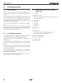
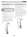
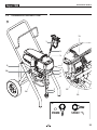
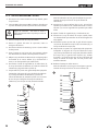
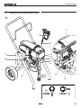
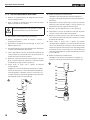
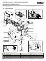
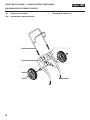
3.3 LEGEND FOR EXPLANATORY DIAGRAM
IMPACT 1040
1. Spray gun
2. High-pressure hose
3. Oil cup for Piston Lube (Piston Lube prevents increased
wear of the packings)
4. Oil level gauge
5. Pail hook
6. Oil button
7. Siphon tube
8. Return hose
9. Cart
10. Relief valve
Lever position vertical – PRIME ( k circulation)
Lever position horizontal – SPRAY ( p)
11. Control panel indicators
12. Pressure control knob
13. ON/OFF switch
14. Pressure gauge

11
description of unit
Impact 1040
3.4 EXPLANATORY DIAGRAM IMPACT 1040
7
8
2
1
3
5
6
4
9
10
14
11
13
12
10*
PRIME SPRAY
k
p

12
description of unit
Impact 1040
3.5 TECHNICAL DATA
Voltage
220~240 VAC, 50/60 Hz
Max. current consumption
8.5 A
Power Cord
See page 90
Max. operating pressure
221 bar (22.1 MPa)
Volume ow at 12 MPa (120 bar) with water
4.5 l/min
Max tip size
0.034 inch – 0.86 mm
Max. temperature of the coating material
43°C
Max viscosity
25.000 MPa·s
Weight
47.6 kg
Special high-pressure hose
DN 6 mm, 15 m, connection thread M 16
x 1.5
Dimensions (L X W X H)
590 x 568 x 748 mm
Altitude
This equipment will operate correctly up
to 2000 m above mean sea level
Vibration
Spray gun does not exceed 2.5m/s
2
Max sound pressure level
80 dB*
* Place of measurement: 1 m distance from unit and
1.60m above oor, 12 MPa (120 bar) operating pressure,
reverberant oor
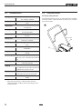
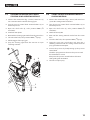
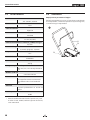
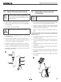
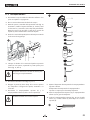
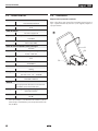
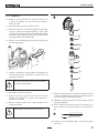
3.6 TRANSPORTATION
Pushing or pulling the unit
Pull out the handle (Fig. 2, Item 1) until it will come no further.
Insert the handle – push the buttons (2) on the spars, and then
push in the handle.
2
1
2

13
starting operation
Impact 1040
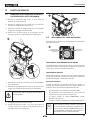
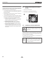
4 STARTING OPERATION
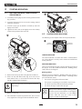
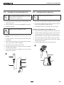
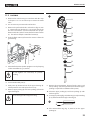
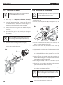
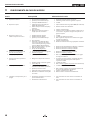
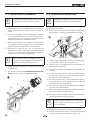
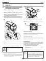
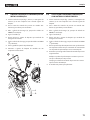
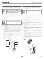
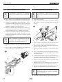
4.1 HIGHPRESSURE HOSE, SPRAY GUN AND
SEPARATING OIL
1. Screw the pressure gauge (1) to the coating material outlet
(Fig. 3, Item 2).
2. Screw the high-pressure hose (3) to the coating material
outlet (Fig. 2, Item 4).
3. Screw the spray gun (5) with the selected tip onto the
high-pressure hose.
4. Tighten the union nuts at the high-pressure hoses rmly
so that coating material does not leak.
2
3
1
4
5
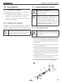
5. Remove the oil cup cap with a straight-slot screwdriver.
6. Fill the oil cup with Piston Lube (Fig. 4). Do not use too
much Piston Lube, i.e. ensure that no Piston Lube drips
into the coating material container.
Piston Lube prevents increased wear and tear to
the packings.
7. Replace oil cup cap.
8. Press oil button 2-5 times to prime the oiler. Press once for
every eight hours of usage to lubricate the uid section.
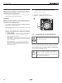
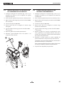
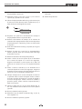
4.2 CONTROL PANEL INDICATORS
The following is a description of the control panel indicators.
Pressure
Indicator
Service
Indicator
SERVICE INDICATOR
The Service indicator is on when the motor is commanded to
run. This indicator is used by service centers to troubleshoot
motor problems.
PRESSURE INDICATOR
The pressure indicator shows the current operating pressure of
the sprayer. It has three dierent indications: blinking yellow,
solid yellow, and solid green.
Blinking Yellow
When the pressure indicator is blinking yellow, the sprayer is
operating between 0 and 1.4 MPa (14 bar). A blinking yellow
pressure indicator means:
• The sprayer is plugged in and turned “ON”
• The sprayer is at priming pressure (little or no pressure)
• It is safe to move the relief valve between positions
• It is safe to change or replace the spray tip
i
If the pressure indicator begins blinking yellow
when the pressure control knob is set at a higher
pressure and the relief valve is in the SPRAY
position, either the spray tip is worn or the
sprayer is in need of service/repair.

14
starting operation
Impact 1040
Solid Yellow
When the pressure indicator is solid yellow, the sprayer is
operating between 1.4 MPa (14 bar) and 12 MPa (120 bar). A
solid yellow pressure indicator means:
• The sprayer is at the proper pressure setting for spraying
stain, lacquer, varnish, and multi-colors
Solid Green
When the pressure indicator is solid green, the sprayer is
operating between 12 MPa (120 bar) and 23 MPa (230 bar). A
solid green pressure indicator means:
• The sprayer is at the proper pressure setting for spraying
oil-based and latex house paints
• The sprayer is operating at peak performance at a high
pressure setting
• If the pressure indicator goes to solid yellow when the
pressure is set so that it starts at solid green, it indicates
one of the following:
a. Tip Wear Indicator — when spraying with latex or at high
pressure the solid yellow appears. This means the tip is
worn and needs to be replaced.
b. Tip Too Large — when a tip that is too large for the sprayer
is put in the gun, the pressure indicator will turn from solid
green to solid yellow.
c. Fluid Section Wear — if a solid yellow pressure indicator
appears when using a new tip and the pressure is set at
maximum, service may be required (worn packings, worn
piston, stuck valve, etc...).
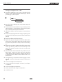
4.3 PRESSURE CONTROL KNOB SETTINGS
1. Minimum pressure setting
2. Black zone – no pressure generation
3. Blue zone – pulsating pressure for cleaning
1
2
3
4.4 CONNECTION TO THE MAINS NETWORK
The unit must be connected to an appropriately-
grounded safety outlet.
Before connecting the unit to the mains supply, ensure that the
line voltage matches that specied on the unit’s rating plate.
The connection must be equipped with a residual current
protective device with INF ≤ 30 mA.
i
Titan‘s accessories program also includes a
mobile operator protection device for the
electronic supply, which can also be used with
other electronic equipment.

15
starting operation
Impact 1040
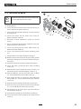
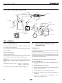
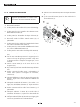
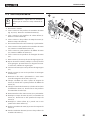
4.5 CLEANING PRESERVING AGENT WHEN
STARTINGUP OF OPERATION INITIALLY
1. Immerse the suction tube (Fig. 7, Item 2) return hose (1)
into a container with a suitable cleaning agent.
2. Turn the pressure control knob counterclockwise (3) to
minimum pressure.
3. Open the relief valve (4), valve position PRIME (k
circulation).
4. Switch the unit (5) ON.
5. Wait until the cleaning agent exudes from the return hose.
6. Close the relief valve, valve position SPRAY (p spray).
7. Pull the trigger of the spray gun.
8. Spray the cleaning agent from the unit into an open
collecting container.
1
2
3
5
4
4.6 TAKING THE UNIT INTO OPERATION WITH
COATING MATERIAL
1. Immerse the suction tube (Fig. 7, Item 2) and return hose
(1) into the coating material container.
2. Turn the pressure control knob counterclockwise (3) to
minimum pressure.
3. Open the relief valve (4), valve position PRIME (k
circulation).
4. Switch the unit (5) ON.
5. Wait until the coating material exudes from the return
hose.
6. Close the relief valve, valve position SPRAY (p spray).
7. Trigger the spray gun several times and spray into a
collecting container until the coating material exits the
spray gun without interruption.
8. Increase the pressure by slowly turning up the pressure
control knob.
Check the spray pattern and increase the pressure until
the atomization is correct.
Always turn the pressure control knob to the lowest
setting with good atomization.
9. The unit is ready to spray.

16
spraying
Impact 1040
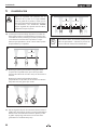
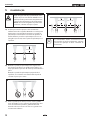
5 SPRAYING
Injection hazard. Do not spray without the tip
guard in place. NEVER trigger the gun unless
the tip is completely turned to either the spray
or the unclog position. ALWAYS engage the
gun trigger lock before removing, replacing or
cleaning tip.
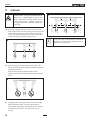
A) The key to a good paint job is an even coating over the
entire surface. Keep your arm moving at a constant speed
and keep the spray gun at a constant distance from the
surface. The best spraying distance is 10-12 inches (25 to
30 cm) between the spray tip and the surface.
25 - 30 cm
A
B) Keep the spray gun at right angles to the surface. This
means moving your entire arm back and forth rather than
just exing your wrist.
Keep the spray gun perpendicular to the surface,
otherwise one end of the pattern will be thicker than the
other.
B
C) Trigger gun after starting the stroke. Release the trigger
before ending the stroke. The spray gun should be
moving when the trigger is pulled and released. Overlap
each stroke by about 30%. This will ensure an even
coating.
25 - 30 cm25 - 30 cm
C
i
If very sharp edges result or if there are streaks in
the spray jet – increase the operating pressure or
dilute the coating material.

17
handling the high pressure hose / interruption of work
Impact 1040
6 HANDLING THE HIGHPRESSURE HOSE
i
The unit is equipped with a high-pressure hose
specially suited for piston pumps.
Danger of injury through leaking high-pressure
hose. Replace any damaged high-pressure hose
immediately.
Never repair defective high-pressure hoses
yourself!
The high-pressure hose is to be handled with care. Avoid sharp
bends and folds: the smallest bending radius is about 8” (20 cm).
Do not drive over the high-pressure hose. Protect against sharp
objects and edges.
Never pull on the high-pressure hose to move the device.
Make sure that the high-pressure hose cannot twist. This can
be avoided by using a Titan spray gun with a swivel joint and a
hose system.
i
When using the high-pressure hose while
working on scaolding, it is best to always guide
the hose along the outside of the scaolding.
i
The risk of damage rises with the age of the
high-pressure hose. Titan recommends replacing
high-pressure hoses after 6 years.
i
Use only Titan original-high-pressure hoses
in order to ensure functionality, safety and
durability.
7 INTERRUPTION OF WORK
1. Open the relief valve, valve position PRIME (k circulation).
2. Switch the unit OFF.
3. Turn the pressure control knob counterclockwise to
minimum pressure.
4. Pull the trigger of the spray gun in order to release the
pressure from the high-pressure hose and spray gun.
5. Secure the spray gun, refer to the operating manual of the
spray gun.
6. If a standard tip is to be cleaned, see Page 28, Section 12.2.
If a non-standard tip is installed, proceed according to the
relevant operating manual.
7. Depending on the model, leave the suction tube or the
suction hose and return hose immersed in the coating
material or swivel or immerse it into a corresponding
cleaning agent.
If fast-drying or two-component coating material
is used, ensure that the unit is rinsed with a
suitable cleaning agent within the processing
time.

18
cleaning the unit (shutting down)
Impact 1040
8 CLEANING THE UNIT SHUTTING
DOWN
i
A clean state is the best method of ensuring
operation without problems. After you have
nished spraying, clean the unit. Under no
circumstances may any remaining coating
material dry and harden in the unit.
i
The cleaning agent used for cleaning (only with
an igni tion point above 38 °C) must be suitable
for the coating material used.
i
• Secure the spray gun, refer to the operating
manual of the spray gun.
• Clean and remove tip.
For a standard tip, refer to Page 28, Section
12.2.
• If a non-standard tip is installed, proceed
according to the relevant operating manual.
1. Remove suction hose from the coating material.
2. Close the relief valve, valve position SPRAY (p spray).
3. Switch the unit ON.
The container must be earthed in case of coating
materials which contain solvents.
Caution! Do not pump or spray into a container
with a small opening (bunghole)!
4. Pull the trigger of the spray gun in order to pump the
remaining coating material from the suction hose, high-
pressure hose and the spray gun into an open container.
5. Immerse suction hose with return hose into a container
with a suitable cleaning agent.
6. Turn the pressure control knob counterclockwise to
minimum pressure.
7. Open the relief valve, valve position PRIME (k circulation).
8. Pump a suitable cleaning agent in the circuit for a few
minutes.
9. Close the relief valve, valve position SPRAY (p spray).
10. Pull the trigger of the spray gun.
11. Pump the remaining cleaning agent into an open container
until the unit is empty.
12. Switch the unit OFF.
8.1 CLEANING UNIT FROM OUTSIDE
First of all pull out mains plug from socket.
tention
Danger of short circult through penetrating
water!
Never spray down the unit with high-pressure or
high-pressure steam cleaners.
Do not put the high-pressure hose into solvents.
Use only a wet cloth to wipe down the outside of
the hose.
Wipe down unit externally with a cloth which has been
immersed in a suitable cleaning agent.
8.2 SUCTION FILTER
i
A clean suction lter always guarantees maximum
feed quantity, constant spraying pressure and
problem-free functioning of the unit.
1. Screw o the lter (Fig. 8) from suction tube.
2. Clean or replace the lter.
Carry out cleaning with a hard brush and an appropriate
cleaning agent.

19
cleaning the unit (shutting down)
Impact 1040
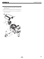
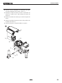
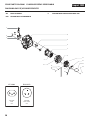
8.3 CLEANING THE HIGHPRESSURE FILTER
i
Clean the lter cartridge regularly. A soiled or
clogged high-pressure lter can cause a poor
spray pattern or a clogged tip.
1. Turn the pressure control knob counterclockwise to
minimum pressure.
2. Open the relief valve, valve position PRIME (k circulation).
3. Switch the unit OFF.
Unplug the power plug from the outlet.
4. Unscrew the lter housing (Fig. 9, Item 1) with a strap
wrench.
5. Turning clockwise, unscrew the lter (2) from the pump
manifold (3).
6. Clean all the parts with the corresponding cleaning agent.
If necessary, replace the lter cartridge.
7. Check the O-ring (4), replace it if necessary.
8. Turning counterclockwise, screw the new or cleaned lter
into the pump manifold.
9. Screw in lter housing (1) and tighten it as far as possible
with the strap wrench.
1
2
3
5
4
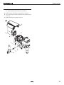
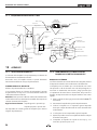
8.4 CLEANING AIRLESS SPRAY GUN
i
Clean the spray gun after each use.
1. Rinse airless spray gun with an appropriate cleaning agent.
2. Clean tip thoroughly with appropriate cleaning agent so
that no coating material residue remains.
3. Thoroughly clean the outside of the airless spray gun.
INTAKE FILTER IN AIRLESS SPRAY GUN FIG. 10
1. Unclip the top of the trigger guard (1) from the gun head.
2. Using the bottom of the trigger guard as a wrench, loosen
and remove the handle assembly (2) from the gun head.
3. Pull the old lter (3) out of the gun head. Clean or replace.
4. Slide the new lter, tapered end rst, into the gun head.
5. Thread the handle assembly into the gun head. Tighten
with the trigger wrench.
6. Snap the trigger guard back onto the gun head.
1
2
3

20
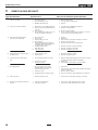
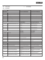
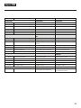
remedy in case of faults
Impact 1040
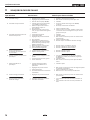
Type of malfunction
A. Unit does not start
B. Unit does not draw in material
C. Unit draws in material, but the
pressure does not build up
D. Coating material exits at the top of
the uid section
E. Increased pulsation at the spray
gun
F. Poor spray pattern
G. Unit loses power
H. Pump over-pressurizes and will not
shut o.
Possible cause
1. No voltage applied.
2. Pressure setting too low.
3. ON/OFF switch defective.
1. Relief valve is set to SPRAY (p spray).
2. Filter projects over the uid level and
sucks air.
3. Filter clogged.
4. Suction hose/suction tube is loose, i.e.
the unit is sucking in outside air.
1. Tip heavily worn.
2. Tip too large.
3. Pressure setting too low.
4. Filter clogged.
5. Coating material ows through the
return hose when the relief valve is in
the SPRAY (p spray) position.
6. Packings sticky or worn.
7. Valve balls worn.
8. Valve seats worn.
1. Upper packing is worn.
2. Piston is worn.
1. Incorrect high-pressure hose type.
2. Tip worn or too large.
3. Pressure too high.
1. Tip is too large for the coating
material which is to be sprayed.
2. Pressure setting incorrect.
3. Volume too low.
4. Coating material viscosity too high.
1. Pressure setting too low.
1. Pressure switch defective.
2. Transducer defective.
Measures for eliminating the malfunction
1. Check voltage supply.
2. Turn up pressure control knob.
3. Replace.
1. Set relief valve to PRIME (k circulation).
2. Rell the coating material.
3. Clean or replace the lter.
4. Clean connecting points. Replace O-rings if necessary.
Secure suction hose with retaining clip.
1. Replace
2. Replace tip.
3. Turn pressure control knob clockwise to increase.
4. Clean or replace the lter.
5. Remove and clean or replace relief valve.
6. Remove and clean or replace packings.
7. Remove and replace valve balls.
8. Remove and replace valve seats.
1. Remove and replace packing.
2. Remove and replace piston.
1. Only use TITAN original-high-pressure hoses in order to
ensure functionality, safety and durability.
2. Replace tip.
3. Turn pressure control knob to a lower number.
1. Replace tip.
2. Turn pressure control knob until a satisfactory spraying
pattern is achieved.
3. Clean or replace all lters.
4. Thin out according to the manufacturer’s instructions.
1. Turn pressure control knob clockwise to increase.
1. Take unit to a Titan authorized service center.
2. Take unit to a Titan authorized service center.
9 REMEDY IN CASE OF FAULTS
A página está carregando...
A página está carregando...
A página está carregando...
A página está carregando...
A página está carregando...
A página está carregando...
A página está carregando...
A página está carregando...
A página está carregando...
A página está carregando...
A página está carregando...
A página está carregando...
A página está carregando...
A página está carregando...
A página está carregando...
A página está carregando...
A página está carregando...
A página está carregando...
A página está carregando...
A página está carregando...
A página está carregando...
A página está carregando...
A página está carregando...
A página está carregando...
A página está carregando...
A página está carregando...
A página está carregando...
A página está carregando...
A página está carregando...
A página está carregando...
A página está carregando...
A página está carregando...
A página está carregando...
A página está carregando...
A página está carregando...
A página está carregando...
A página está carregando...
A página está carregando...
A página está carregando...
A página está carregando...
A página está carregando...
A página está carregando...
A página está carregando...
A página está carregando...
A página está carregando...
A página está carregando...
A página está carregando...
A página está carregando...
A página está carregando...
A página está carregando...
A página está carregando...
A página está carregando...
A página está carregando...
A página está carregando...
A página está carregando...
A página está carregando...
A página está carregando...
A página está carregando...
A página está carregando...
A página está carregando...
A página está carregando...
A página está carregando...
A página está carregando...
A página está carregando...
A página está carregando...
A página está carregando...
A página está carregando...
A página está carregando...
A página está carregando...
A página está carregando...
A página está carregando...
A página está carregando...
A página está carregando...
A página está carregando...
A página está carregando...
A página está carregando...
A página está carregando...
A página está carregando...
A página está carregando...
A página está carregando...
-
 1
1
-
 2
2
-
 3
3
-
 4
4
-
 5
5
-
 6
6
-
 7
7
-
 8
8
-
 9
9
-
 10
10
-
 11
11
-
 12
12
-
 13
13
-
 14
14
-
 15
15
-
 16
16
-
 17
17
-
 18
18
-
 19
19
-
 20
20
-
 21
21
-
 22
22
-
 23
23
-
 24
24
-
 25
25
-
 26
26
-
 27
27
-
 28
28
-
 29
29
-
 30
30
-
 31
31
-
 32
32
-
 33
33
-
 34
34
-
 35
35
-
 36
36
-
 37
37
-
 38
38
-
 39
39
-
 40
40
-
 41
41
-
 42
42
-
 43
43
-
 44
44
-
 45
45
-
 46
46
-
 47
47
-
 48
48
-
 49
49
-
 50
50
-
 51
51
-
 52
52
-
 53
53
-
 54
54
-
 55
55
-
 56
56
-
 57
57
-
 58
58
-
 59
59
-
 60
60
-
 61
61
-
 62
62
-
 63
63
-
 64
64
-
 65
65
-
 66
66
-
 67
67
-
 68
68
-
 69
69
-
 70
70
-
 71
71
-
 72
72
-
 73
73
-
 74
74
-
 75
75
-
 76
76
-
 77
77
-
 78
78
-
 79
79
-
 80
80
-
 81
81
-
 82
82
-
 83
83
-
 84
84
-
 85
85
-
 86
86
-
 87
87
-
 88
88
-
 89
89
-
 90
90
-
 91
91
-
 92
92
-
 93
93
-
 94
94
-
 95
95
-
 96
96
-
 97
97
-
 98
98
-
 99
99
-
 100
100


Titan Impact 1040 Instruções de operação
- Categoria
- Limpadores de alta pressão
- Tipo
- Instruções de operação
em outras línguas
Artigos relacionados
Outros documentos
-
Ryobi RAP200 Manual do proprietário
-
Parkside PFSP 100 - MANUEL 4 Operation and Safety Notes
-
Batavia Paint Spray System Manual do usuário
-
WAGNER ProjectPro 117 Manual do proprietário
-
Magnum XR9 Operation
-
BLACK DECKER HVLP200 Manual do proprietário
-
Graco Inc. 233815 Manual do usuário
-
Black & Decker BDPH400 Manual do usuário
-
Total THSPP4161 Guia de usuario
-
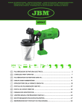 JBM 60043 Guia de usuario
