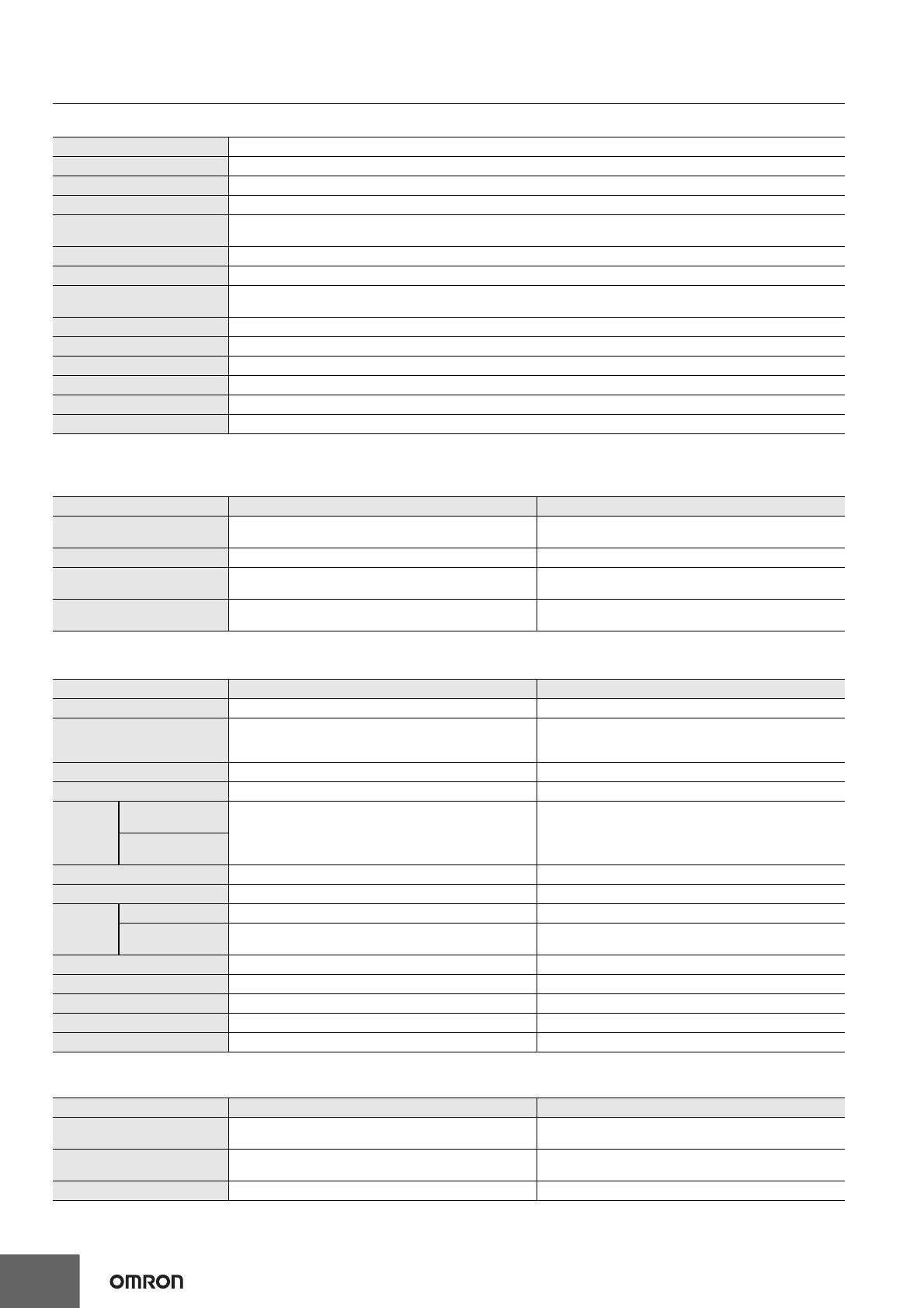
Omron UMA Series Manual do proprietário

Tipo
Manual do proprietário
1
Safety Mat
UMA Series
Easy-to-install safety mat with
advanced features
1 and 2 cable types
Meets EN ISO 13849-1 (PLd/Safety Category 3) and EN
ISO 13856-1
Can be used with MC3 Safety Mat Controller, SCC-1224A
Safety Mat/Edge Controller or NX Safety Controller
Complies with North American safety standards including
ANSI/RIA 15.06
Model Number Structure
Mat Base *
Mat Base *
Mat Dimension B
Mat
Dimension A
UM@@A-@-@-@
1 2 3 4 5
1. Measurement Unit
None: Inch
M: mm
2. Color
None: Black
Y: Yellow
3. Safety Mat Dimension A
4. Safety Mat Dimension B
5. Number of Cables
1: 1 cable (4-wire type)
2: 2 cables (2-wire type) *Refer to Mat Dimensions for the dimensions of the mat base.
UMA Series
2
Ordering Information
Safety Mats
1-cable Mats
2-cable Mats
Appearance Dimensions Black Yellow
A (mm) B (mm) Model Model
300 300 UMMA-0300-0300-1 UMMYA-0300-0300-1
400 400 UMMA-0400-0400-1 UMMYA-0400-0400-1
500 250 UMMA-0500-0250-1 UMMYA-0500-0250-1
500 400 UMMA-0500-0400-1 UMMYA-0500-0400-1
500 500 UMMA-0500-0500-1 UMMYA-0500-0500-1
500 1500 UMMA-0500-1500-1 UMMYA-0500-1500-1
600 400 UMMA-0600-0400-1 UMMYA-0600-0400-1
750 250 UMMA-0750-0250-1 UMMYA-0750-0250-1
750 500 UMMA-0750-0500-1 UMMYA-0750-0500-1
750 750 UMMA-0750-0750-1 UMMYA-0750-0750-1
750 1500 UMMA-0750-1500-1 UMMYA-0750-1500-1
1000 500 UMMA-1000-0500-1 UMMYA-1000-0500-1
1000 750 UMMA-1000-0750-1 UMMYA-1000-0750-1
1000 1000 UMMA-1000-1000-1 UMMYA-1000-1000-1
1000 1250 UMMA-1000-1250-1 UMMYA-1000-1250-1
1000 1500 UMMA-1000-1500-1 UMMYA-1000-1500-1
Appearance Dimensions Black Yellow
A (mm) B (mm) Model Model
300 300 UMMA-0300-0300-2 UMMYA-0300-0300-2
400 400 UMMA-0400-0400-2 UMMYA-0400-0400-2
500 250 UMMA-0500-0250-2 UMMYA-0500-0250-2
500 400 UMMA-0500-0400-2 UMMYA-0500-0400-2
500 500 UMMA-0500-0500-2 UMMYA-0500-0500-2
500 1500 UMMA-0500-1500-2 UMMYA-0500-1500-2
600 400 UMMA-0600-0400-2 UMMYA-0600-0400-2
750 250 UMMA-0750-0250-2 UMMYA-0750-0250-2
750 500 UMMA-0750-0500-2 UMMYA-0750-0500-2
750 750 UMMA-0750-0750-2 UMMYA-0750-0750-2
750 1500 UMMA-0750-1500-2 UMMYA-0750-1500-2
1000 500 UMMA-1000-0500-2 UMMYA-1000-0500-2
1000 750 UMMA-1000-0750-2 UMMYA-1000-0750-2
1000 1000 UMMA-1000-1000-2 UMMYA-1000-1000-2
1000 1250 UMMA-1000-1250-2 UMMYA-1000-1250-2
1000 1500 UMMA-1000-1500-2 UMMYA-1000-1500-2
UMA Series
3
Trims
Note: 12 screws (No. 8-32 × 1.25") and 12 anchors are included with Ramp Trim with Yellow PVC Cover (UMRT4 and UMRT8) and Aluminum
Ramp Trim (UMAL).
Trim Kits (Not Including Safety Mat)
Note: 1. Put 1 in the box (@) in the model number for 1-cable Mat or 2 for 2-cable Mat.
2. 24 screws (No. 8-32 × 1.25") and 24 anchors are included with a Trim Kit.
3. The length of the Ramp Trims with Yellow PVC Covers has been made to fit mat dimensions A and B.
PVC Trim Cover = (Mat dimensions A and B) - 50.8 mm
Appearance Name Model Remarks
Ramp Trim with Yellow PVC Cover
(1.22 m) UMRT4 Installed on the perimeter of the Safety Mat. Each
Trim is composed of two parts, an aluminum base
and a PVC Cover. Possible to install cables inside.
Ramp Trim with Yellow PVC Cover
(2.44 m) UMRT8
Joining Trim (1.22 m) UMJS4 The Joining Trims join the Safety Mats when two or
more Safety Mats are being combined. In addition
to joining the Safety Mats, the Joining Trims
preserve the Safety Mat's sensitivity at the joints.
Possible to install cables inside except M8
connector portion.
Joining Trim (2.44 m) UMJS8
Aluminum Ramp Trim (2.44 m) UMAL Installed on the perimeter of the Safety Mat.
Molded Outside Corner UMOC Installed at the outside corners of the Safety Mat
combining with Ramp Trims with Yellow PVC
Cover.
Molded Inside Corner UMIC Installed at the inside corners when two or more
Safety Mats combining with Ramp Trims with
Yellow PVC Cover are being combined.
Applicable Safety Mat Trim Kit model Remarks
Black Yellow
UMMA-0300-0300-@UMMYA-0300-0300-@MTKCA-0300-0300 A set of Molded Outside Corners and Trims
4 UMOC Molded Outside Corners
4 Ramp Trims with Yellow PVC Corners
that fit the mat dimensions A and B
UMMA-0400-0400-@UMMYA-0400-0400-@MTKCA-0400-0400
UMMA-0500-0250-@UMMYA-0500-0250-@MTKCA-0500-0250
UMMA-0500-0400-@UMMYA-0500-0400-@MTKCA-0500-0400
UMMA-0500-0500-@UMMYA-0500-0500-@MTKCA-0500-0500
UMMA-0500-1500-@UMMYA-0500-1500-@MTKCA-0500-1500
UMMA-0600-0400-@UMMYA-0600-0400-@MTKCA-0600-0400
UMMA-0750-0250-@UMMYA-0750-0250-@MTKCA-0750-0250
UMMA-0750-0500-@UMMYA-0750-0500-@MTKCA-0750-0500
UMMA-0750-0750-@UMMYA-0750-0750-@MTKCA-0750-0750
UMMA-0750-1500-@UMMYA-0750-1500-@MTKCA-0750-1500
UMMA-1000-0500-@UMMYA-1000-0500-@MTKCA-1000-0500
UMMA-1000-0750-@UMMYA-1000-0750-@MTKCA-1000-0750
UMMA-1000-1000-@UMMYA-1000-1000-@MTKCA-1000-1000
UMMA-1000-1250-@UMMYA-1000-1250-@MTKCA-1000-1250
UMMA-1000-1500-@UMMYA-1000-1500-@MTKCA-1000-1500
Molded Outside Corner
Ramp Trims with
Yellow PVC Corner
UMA Series
4
Safety Mat Controller
*Can also be connected with SGE-series Safety Edges.
Refer to the SCC-1224A Safety Mat/Edge Controller User Manual (Cat. No. Z394) for details.
Product Appearance Safety outputs Auxiliary
outputs Rated voltage Terminal block type Model
Safety Mat
Controller SPDT-NO SPDT-NC 24 VDC Screw terminals MC3
Safety Mat/
Edge Controller *SPDT-NO SPST-NO 120 VAC
or
24 VAC/DC Screw terminals SCC-1224A
UMA Series
5
Accessories
Using with 1-cable Mats
Connecting a 1-cable Mat to a MC3 Safety Mat Controller, SCC-1224A Safety Mat/Edge Controller or NX-series Safety Controller.
Cables
Using with 2-cable Mats
Connecting a 2-cable Mat to a MC3 Safety Mat Controller, SCC-1224A Safety Mat/Edge Controller or NX-series Safety Controller.
Cables
Male-Male Extension Cable and Female-Female Extension Cable
Terminating Resistor
Appearance Name Length Remarks Model
Single Connector
Cable
2 m
Single connector cable to connect a 1-cable Mat
(UM@@A-@-@-1) to a Controller. M8, 4-socket
UMA-CBL-4PCF-M8-02M
5 m UMA-CBL-4PCF-M8-05M
10 m UMA-CBL-4PCF-M8-10M
Male-Female
Extension Cable
2 m
Extension cable to connect a 1-cable Mat
(UM@@A-@-@-1) to a Controller. M8, 4-pin
UMA-CBL-4PMF-M8-02M
5 m UMA-CBL-4PMF-M8-05M
10 m UMA-CBL-4PMF-M8-10M
Appearance Name Length Remarks Model
Single Connector
Cable
2 m
Single connector cable to connect a 2-cable Mat
(UM@@A-@-@-2) to a Controller. M8,3-socket
UMA-CBL-3PCF-M8-02M
5 m UMA-CBL-3PCF-M8-05M
10 m UMA-CBL-3PCF-M8-10M
Male-Female
Extension Cable
2 m
Extension cable to connect a 2-cable Mat
(UM@@A-@-@-2) to a Controller. M8,3-pin
UMA-CBL-3PMF-M8-02M
5 m UMA-CBL-3PMF-M8-05M
10 m UMA-CBL-3PMF-M8-10M
Appearance Name Length Remarks Model
M8, 3-pin Male to Male
Extension Cable
0.15 m To be used to connect the connector sockets of 2-
cable UMA Safety Mat together. UMA-CBL-3PMM-M8-0.15M
M8, 3-pin Female to
Female Extension
Cable
0.15 m To be used to connect the connector plugs of 2-
cable UMA Safety Mat together. UMA-CBL-3PFF-M8-0.15M
Appearance Remarks Model
Terminating resistor, 8.2 kΩ
To be used to connect a 2-cable Mat (UM@@A-@-@-2) to an SCC-1224A Safety
Mat/Edge Controller. UMA-TRES
Refer to Connection Examples of Safety Mat and
Controller on page 8 for details on how to connect.
UMA Series
6
Specifications
Safety Mat
Safety Mat Controller
Ratings
*Power consumption of loads is not included.
Characteristics
Approvals
*Applicable to integrated systems of UMA Safety Mats and Safety Mat Controller.
Detection Method Pressure sensitive
Mat Type Normally open SPST
Mat Electrical Rating 20.4 V to 28.8 V
Activation Force 300 N min. to 80 mm dia. test piece
Maximum Load 2,000 N to 80 mm dia. test piece
1,862 kPa (270 lbs/in.2) (rolling load (stationary))
Response Time 50 ms max.
Mechanical Durability 1 x 10⁶ operations min.
Mat Exit Cable Model No. ending ‘-1’: 1 exit cable, M8 4-pin cable, 4 conductors, 22 AWG, male
Model No. ending ‘-2’: 2 exit cables, M8 3-pin cable, 2 conductors, 22 AWG, 1 male and 1 female
Ambient operating temperature -10 to 55°C (14 to 131°F) (with no icing or condensation)
Ambient storage temperature -10 to 55°C (14 to 131°F) (with no icing or condensation)
Ambient operating humidity 0 to 95% RH
Degree of protection IP65
Material (Mat cover) Polyurethane
Weight Approx. 25 kg/m2
Item Model MC3 SCC-1224A
Power voltage 24 VDC 120 VAC 50/60Hz (Terminals A1 and A2)
24 VAC 50/60Hz or 24 VDC (Terminals B1 and B2)
Operating voltage range -15% to +15% of rated supply voltage -10% to +10% of rated supply voltage
Power consumption *3 W max. 120 VAC: 3.8 VA max. 50 Hz, 3.5 VA max. 60 Hz
24 VAC: 1.2 VA max., 24 VDC: 1.5 W max.
Rated load 6 A at 230 VAC/6 A at 24 VDC (resistive load)
5 A at 230 VAC (AC15)/2 A at 24 VDC (DC13) (inductive load) 3 A at 230 VAC/3 A at 24 VDC (resistive load)
1 A at 230 VAC (AC15)/2 A at 24 VDC (DC13) (inductive load)
Item Model MC3 SCC-1224A
Response time 30 ms max. 13 ms max.
Safety input
Mat can be connected in series (Connectable number: 12 max.)
The external impedance must be 8 Ω or less between M11 and
M21 and between M12 and M22.
Mat can be connected in series (Connectable number: 10 max.)
Safety output SPDT-NO SPDT-NO
Auxiliary output SPDT-NC SPST-NO
Dielectric
strength
Between different
poles of outputs 1,800 VAC, 50/60 Hz for 1 sec. 1,500 VAC, 50/60 Hz for 1 sec.
Between power
supply and output
Vibration resistance Malfunction: 10 to 55 Hz, 0.15 mm single amplitude Malfunction: 10 to 55 Hz, 0.15 mm single amplitude
Mechanical shock resistance Malfunction: 98 m/s2Malfunction: 147 m/s2
Durability Mechanical 10,000,000 cycles min. 1,000,000 cycles min.
Electrical 100,000 cycles min. (rated load, switching frequency: 360
cycles/hour) AC-15: 800,000 cycles min. (1A at 230 VAC)
DC-13: 250,000 cycles min. (2A at 24 VDC)
Ambient operating temperature 0 to 55°C (with no icing or condensation) -20 to 55°C (with no icing or condensation)
Ambient operating humidity 0% to 90% RH 0% to 90% RH
Degree of protection IP20 IP20
Terminal tightening torque 0.5 N·m 0.5 to 0.6 N·m
Weight Approx. 360 g Approx. 210 g
Item Model MC3 SCC-1224A
Conforming to Standards EN ISO13856-1:2013, EN ISO13849-1:2015, ANSI/UL 508,
CSA C22.2 No. 14 EN ISO 13856-1:2013, EN ISO 13849-1:2015, ANSI/UL 508,
CSA C22.2 No. 14
Performance level (PL)/
safety category *PL d/safety category 3 (EN ISO 13849-1:2015) PL d/safety category 3 (EN ISO 13849-1:2015)
PFHd *4.8×10⁻⁸ 6.5×10⁻⁹
UMA Series
7
Installation
Using Trim Pieces
Ramp Trim with Yellow PVC Cover: UMRT4/UMRT8
Secures the edges of the Safety Mats to the floor.
It is composed of two parts with an aluminum base and a PVC Cover.
Joining Trim: UMJS4/UMJS8
The Joining Trims join the Safety Mats when two or more Safety Mats
are being combined.
In addition to joining the Safety Mats, the Joining Trims preserve the
Safety Mat's sensitivity at the joints.
Aluminum Ramp Trim: UMAL
Secures the edges of the Safety Mat to the floor.
The Aluminum Ramp Trim is hollow, so cable can be routed through
it.
Molded Outside Corner: UMOC
Used together with the Ramp Trim with Yellow PVC Cover (UMRT4/
UMRT8) to secure the external corners of the Safety Mats to the floor.
Molded Inside Corner: UMIC
Used together with the Ramp Trim with Yellow PVC Cover (UMRT4/
UMRT8) to secure the internal corners of the Safety Mats to the floor.
Note: 1. The Aluminum Ramp Trim or Ramp Trim with Yellow PVC
Cover must be cut to fit the size of the Safety Mats being
used.
Furthermore, when the Safety Mat's wiring is being routed
through the Aluminum Ramp Trim or Ramp Trim with Yellow
PVC Cover, it will be necessary to cut or notch the
Aluminum Ramp Trim or Ramp Trim with Yellow PVC Cover
for cable access.
Refer to UMA Safety Mat User Manual (Man. No. Z375-E1)
for details on cutting or notching the Aluminum Ramp Trim
or Ramp Trim with Yellow PVC Cover.
2. The Joining Trim must be cut to fit the size of the Safety
Mats being used.
3. The Ramp Trim with Yellow PVC Cover and Molded Corner
must be anchored to the floor to secure the Safety Mats. It
is also necessary to drill holes in the Trim to anchor it.
Refer to UMA Safety Mat User Manual (Man. No. Z375-E1)
for details on drilling holes in the Trim and Molded Corner
and anchoring it to the floor.
Safety Mat Configuration
The Safety Mats are secured by anchoring the Ramp Trim with Yellow
PVC Cover and Molded Corner to the floor.
Before ordering, confirm the number of Ramp Trim with Yellow PVC
Cover and Molded Corner pieces that will be needed.
Example 1: Using a Single Safety Mat
In this case, the perimeter of the Safety Mat is about 4 m and the
following pieces are required:
The example above consists of the following components:
UMMA-1000-1000 Safety Mat : 1 piece
UMRT4 Ramp Trim with Yellow PVC Cover (1.22 m): 4 pieces
UMOC Molded Outside Corner : 4 pieces
Example 2: Using three Safety Mats
In this case, the perimeter of the Safety Mat is about 8 m, the joint
between the Safety Mats is 2-m long, and the following pieces are
required:
The example above consists of the following components:
UMMA-1000-1000 Safety Mat : 3 pieces
UMRT4 Ramp Trim with Yellow PVC Cover (1.22 m): 8 pieces
UMJS4 Joining Trim (1.22 m) : 2 pieces
UMOC Molded Outside Corner : 5 pieces
UMIC Molded Inside Corner : 1 piece
UMMA-1000-1000-2
UMOC
UMRT4
UMOC
UMRT4
UMOC
UMOC
UMIC
UMJS4
UMMA-1000-1000-2
UMMA-1000-1000-2UMMA-1000-1000-2
UMA Series
8
Connection Examples of Safety Mat and Controller
Using a Single Safety Mat
Connecting a 1-cable Mat (UM@@A-@-@-1) to a MC3 Safety Mat Controller or SCC-1224A Safety Mat/Edge Controller.
Using Multiple Safety Mats
Connecting three 2-cable Mats (UM@@A-@-@-2) to a SCC-1224A Safety Mat/Edge Controller.
Connecting three 2-cable Mats (UM@@A-@-@-2) to a MC3 Safety Mat Controller.
Note: 1. When an MC3 is used, the total cable length is up to 100 m and up to 12 Safety Mats can be connected (up to 10 m2 in total).
When an SCC-1224A is used, the total cable length is up to 25 m and up to 10 Safety Mats can be connected (up to 10 m2 in total).
For the 1-cable type of UMA Safety Mat (UM@@A-@-@-1), the total lone length of cable must be calculated by multiplying the total length
of the cables used by two.
2. The required accessories vary depending on the mat configuration and layout.
4 conductors
4 pins (Male)
UMA-CBL-4PCF-M8-@M
M8 4-pin single connector cable
UMA Safety Mat
M11
Safety Mat Controller
MC3 Terminals
BrownBlack Blue White Brown BlackBlue White
M12 M21 M22 X1
Safety Mat/Edge Controller
SCC-1224A Terminals
X2 X4 X3
UMA Safety Mat UMA Safety Mat UMA Safety Mat
Terminating
Resistor (UMA-TRES)
2 conductors
3 pins (Male)
2 conductors
3 pins (Female)
UMA-CBL-3PMF-M8-@M
M8 3-pin extension cable
UMA-CBL-3PCF-M8-@M
M8 3-pin single connector cable
Brown Blue
X1 or X2 X2 or X1
Safety Mat/Edge Controller
SCC-1224A Terminals
2 conductors
3 pins (Male)
2 conductors
3 pins (Female)
UMA-CBL-3PCF-M8-@M
M8 3-pin single connector cable
Safety Mat Controller
MC3 Terminals
Blue
M11 M12 M21 M22
BrownBlue Brown
2 conductors
3 pins (Male)
UMA-CBL-3PCF-M8-@M
M8 3-pin single connector cable
UMA-CBL-3PMM-M8-0.15M
M8 3-pin male-male extension cable
UMA Safety MatUMA Safety MatUMA Safety Mat
UMA Series
9
Connections
MC3
Internal Connection
Wiring of Inputs and Outputs
Signal name Terminal name Description of operation Wiring
Power supply
input Y1, Y2 Power supply input terminals for MC3
Connect the power source to the Y1 and Y2 terminals.
Connect the power supply plus (24 VDC) to the Y1
terminal.
Connect the power supply minus (GND) to the Y2
terminal.
Safety Mat
input M11, M12,
M21, M22
To turn ON safety outputs, all the connected safety
mats must have no load.
Otherwise, the safety outputs will NOT turn ON.
Reset input X1, X2
The Safety Outputs can be turned ON only after the
connection between X1 and X2 closes and then opens.
If the connection between X1 and X2 does not close
and open, the Safety Outputs will not turn ON.
Manual Reset
Mode
The normal operation can be made if the connection
between X1 and X2 is open. Auto Reset Mode
Safety output 13-14, 23-24
The Safety Outputs are turned ON and OFF according to
the status of the Safety Mat inputs and the reset input.
Keep these outputs Open when NOT used.
Auxiliary
output 31-32, 41-42 Turns ON/OFF according to the state of the opposite
logic to the safety outputs. Keep these outputs Open when NOT used.
Control Circuit
Power
supply
M21
42322414
2313
X2X1
Y1Y2
31 41
M12M11 M22
Y2
13 14 23 24 31 32 41 42
Y1 X1 X2
M11 M12 M21 M22
LED (green)
23 24
14
13
Safety output 31 32
Auxiliary output
X1 X2
Reset input
M11 M12
Safety Mat input
Safety output
Y2
Y1
Power supply
input
Auxiliary output
Lights when Safety Mat
is not being activated
(i.e., when intrusion is
not being detected)
LED (red)
Lights when the safety output
from the MC3 Safety Mat
Controller is OFF
LED (green)
Lights when the safety output
from the MC3 Safety Mat
Controller is ON
41
42
Safety Mat input
M22
M21
Mat ClearStop Run
M12
Brown Safety Mat
UMA
Black
White
Blue
Blue
White
M11
M21
M22
X1
X2
UMA Series
10
Changing the Reset Mode
You can select either the Auto Reset Mode or the Manual Reset Mode with the MC3 Controller.
Remove the terminal block from the top of the MC3 Controller to expose three yellow jumpers. Set the jumps as required by system specifications.
Auto Reset Mode (Factory Setting)
Leave all three jumpers connected. Manual Reset Mode
Remove all three jumpers.
Three yellow jumpers
Terminal block removed
from top of Controller
UMA Series
11
Connection Terminals
Signal Indicators
Signal Terminal Overview Wiring
Supply Voltage 120 VAC A1, A2 Input terminals of 120 VAC supply voltage. Do not connect a supply voltage of 24 VAC or 24 VDC.
Supply Voltage 24 VAC/DC B1, B2 Input terminals of 24 VAC or 24 VDC supply voltage. Do not connect a supply voltage of 120 VAC. When using
24 VDC, connect 24 VDC line to B1 and 0 VDC line to B2.
Connection Sensor X1, X2 Input terminals of sensor signal.
Connect signal lines of UMA Safety Mat.
For 1-cable type of UMA Safety Mat (UM@@A-@-@-1),
connect brown line to X1 and blue line to X2.
X3, X4 Connect signal lines of 1-cable type of UMA Safety Mat
(UM@@A-@-@-1), white line to X3 and black line to X4.
Manual Reset Z1, Z2 Input terminals of a reset switch (NO contact). Also used as
external device monitoring (EDM) terminals of contactors.
Do not connect any lines when in the automatic reset
mode. Connect NC contacts of contactors when using the
external device monitoring (EDM) function.
Safety Output 1 13-14
Closed or open according to sensor and manual reset inputs.
Do not connect any lines when not used.
Remove the factory-installed jumper between terminals 14
and 23 if safety outputs 1 and 2 are not connected in
series.
Safety Output 2 23-24
Auxiliary Output 31-32
In the auxiliary output without delay mode, the auxiliary output
is closed without delay when the safety outputs are open.
In the auxiliary output delayed mode, the auxiliary output is
closed with a delay of 0.5 s after the safety outputs are open,
and remains closed for 3 s.
Do not connect any lines when not used.
Do not use this as safety output.
Label Color Name Status Description
Power Green Power LED ON Operating state
Flashing Fault alarm
CH1 Red Sensor Input LED
ON Sensor activated (Safety output OFF)
Fast flashing (approx. 4 Hz) Sensor faulty
Slow flashing (approx. 1 Hz) Waiting for reset switch input (Safety output OFF)
OFF Released from interlocked state (Safety output ON)
AUX1 Yellow Auxiliary output LED ON Auxiliary output contact closed
OFF Auxiliary output contact open
Connection
Sensor
Safety
Output
Auxiliary
Output
Manual Reset
AC/DC
A1
X1 X2
Z1 Z2
X3 X4 13 23 31
14 24 32
A2
B1
B2
SCC-1224A
Internal Connection
Power
CH1
AUX1
SCC-1224A
Connection Sensor
Switching
LED Power (green)
LED CH 1 (red)
LED AUX 1 (yellow)
Contact
Aux Output
Manual Reset
Supply Voltage
24 VAC/DC
50/60Hz
X1
X2
23 24
3132
Z1
B2 B1
1413
A2 A1
Z2
Connection Sensor
Z1 Z2 X3 X4
B1 B2 X1 X2
A1 A2 31 32
13 14 23 24
X3 X4
Supply Voltage
120VAC 50/60Hz
Switching
Contact
Safety Output 2
Switching
Contact
Safety Output 1
* Remove the factory-installed jumper between
terminals 14 and 23 if safety outputs 1 and 2
are not connected in series.
Factory
Installed
Jumper*
Wiring of Inputs and Outputs
UMA Series
12
Dimensions (Unit: mm)
*1. Refer to Model Number Structure on page 1 for more information.
*2. "Step" portion of mat (inactive) is used to "seat/place/hold" trim.
*3. The mat has the following inactive (non-sensing) area:
- 10 mm (20 mm at corners) with a test piece of 80 mm diameter
- 15 mm (30 mm at corners) with a test piece of 11 mm diameter
Example dimensions: UMMA-0500-0500-@
M8, 4-pin 4-wire male
UMMA-1000-1500-1 (shown)
Cable exits right hand corner of “B” side
Dead zone
6.35 (0.25) Step
5.00 (0.2)
130.00
(5.12)
“B”
1500
shown
“A”
1000
6.35
(0.25)
6.35
(0.25)
Unit: mm (Inches)
M8, 3-pin 2-wire male
M8, 3-socket 2-wire female
Dead zone
6.35 (0.25) Step
3.4 (0.13)
“B”
1500
shown
“A”
1000
UMMA-1000-1500-2 (shown)
(2) Cable exit on corners of “B” side
6.35
(0.25)
6.35
(0.25)
130.00
(5.12)
Unit: mm (Inches)
Safety Mat
1-cable mat
UM@@A-@-@-1 2-cable mat
UM@@A-@-@-2
The UM@@A-@-@-1 mat comes with a short 4-conductor quick discon-
nect cables with M8 4-pin connector at a corner of the safety mat. The UM@@A-@-@-2 mat comes with two short 2-conductor quick dis-
connect cables with M8 3-pin connector at two corners of the safety mat.
Mat Step *2: 6.35 (0.25)
12.7 (0.5)
Dead Zone *3
Mat Base: Mat Dimension A or B*1 + 12.70 (0.50)
Mat Dimension A or B *1Dead Zone *3
Mat Step *2: 6.35 (0.25)
6.35 (0.25)
6.35 (0.25)
Unit: mm (inches)
500
512.7
UMA Series
13
(Unit: mm)
110
84 75
55 15.3 98 38
61.2
Two, R2.2
Y2
13 14 23 24 31 32 41 42
Y1X1X2
M11 M12 M21 M22
Stop
Run
Mat Clear
LED (red)
Lights when the safety
output from the MC3
Safety Mat Controller is
OFF
LED (green)
Lights when the safety
output from the MC3
Safety Mat Controller is
ON
LED (green)
Lights when
Safety Mat is not
being activated
(i.e., when intrusion
is not being detected)
Mat Controller
MC3 Terminal/LED arrangements
11422.5
99
Power
CH1
AUX1
SCC-1224A
Z1 Z2 X3 X4
B1 B2 X1 X2
A1 A2 31 32
13 14 23 24
Power
CH1
AUX1
24
32
13
A1
14
A2
23
31
X4X3Z2Z1
X2X1B2B1
Safety Mat/Edge Controller
SCC-1224A Terminal arrangements
UMA Series
14
(Unit: mm)
Accessories
Cables
Using with 1-Cable Mats
Using with 2-Cable Mats
"L"
70
M8, 4-socket female, rotating, IP65
37.1
3
4
1
2
1
2
3
4
Blue (22 AWG)
Brown (22 AWG)
White (22 AWG)
Black (22 AWG)
5.0 dia. 9.5 dia.
Ferrules
(22 AWG)
Jacket (Polyurethane)
Single Connector Cable (M8, 4-socket)
Single connector cable to connect a 1-cable UMA Safety Mat to a MC3 Safety Mat Controller, SCC-
1224A Safety Mat/Edge Controller or NX-series Safety Controller.
UMA-CBL-4PCF-M8-@M
Model L (m)
UMA-CBL-4PCF-M8-02M 2
UMA-CBL-4PCF-M8-05M 5
UMA-CBL-4PCF-M8-10M 10
End “B”
M8, 4-socket female, rotating, IP65
End “A”
M8, 4-pin male, non-rotating, IP65
End “A” (22 AWG)
(22 AWG)
(22 AWG)
(22 AWG)
1
3
4
2
1
3
4
2
Brown
Blue
White
Black
2
3
4
1
13
42
End “B”
5.0 dia.
Jacket (Polyurethane)
“L
36.1 37.1
9 dia. 9.5 dia.
Model L (m)
UMA-CBL-4PMF-M8-02M 2
UMA-CBL-4PMF-M8-05M 5
UMA-CBL-4PMF-M8-10M 10
Male-Female Extension Cable (M8, 4-pin)
Extension cable to connect a 1-cable UMA Safety Mat to a UMA-CBL-4PCF-M8-@M Single
Connector Cable.
UMA-CBL-4PMF-M8-@M
1
3
4
No connection
Blue (22 AWG)
Brown (22 AWG)
3
1
4
3.4 dia. 9.5 dia.
M8, 3-socket female, rotating, IP65
Ferrules
(22 AWG) Jacket (Polyurethane)
“L
70 37.1
Model L (m)
UMA-CBL-3PCF-M8-02M 2
UMA-CBL-3PCF-M8-05M 5
UMA-CBL-3PCF-M8-10M 10
Single Connector Cable (M8, 3-socket)
Single connector cable to connect a 2-cable UMA Safety Mat to a MC3 Safety Mat Controller,
SCC-1224A Safety Mat/Edge Controller or NX-series Safety Controller.
UMA-CBL-3PCF-M8-@M
UMA Series
15
(Unit: mm)
1
3
4
End “B”
M8, 3-socket female, rotating, IP65
“L”
End “A”
M8, 3-pin male, non-rotating, IP65
36.1
4
1
3
End “A”
No connection
No connection
End “B”
Brown
Blue
1
3
4
1
3
4
(22AWG)
(22AWG)
37.1
3.4 dia.
9 dia. 9.5 dia.
Jacket (Polyurethane)
Model L (m)
UMA-CBL-3PMF-M8-02M 2
UMA-CBL-3PMF-M8-05M 5
UMA-CBL-3PMF-M8-10M 10
Male-Female Extension Cable (M8, 3-pin)
Extension cable to connect a 2-cable UMA Safety Mat to a UMA-CBL-3PCF-M8-@M
Single Connector Cable or connect multiple 2-cable UMA Safety Mats in series.
UMA-CBL-3PMF-M8-@M
3
1
(22 AWG)
(22 AWG)
3
1
44
152.0
36.1
9 dia. 3.4 dia.
36.1 9 dia.
End “A”
M8, 3-pin male, non-rotating, IP65
1
3
4
No Connection
End “A”
End “B”
M8, 3-pin male, non-rotating, IP65
3
1
4
No Connection
Brown
Blue
End “B”
Jacket (Polyurethane)
Male-Male Extension Cable (M8, 3-pin)
Used to connect the connector sockets of 2-cable UMA Safety Mats together.
UMA-CBL-3PMM-M8-0.15M
3
1
43
1
(22 AWG)
(22 AWG)
3
1
44
152.0
4
3
1
9.5 dia.
9.5 dia. 3.4 dia.
37.1
37.1
No Connection No Connection
End “A” End “B”
Brown
Blue
End “A”
M8, 3-socket female, rotating, IP65 End “B”
M8, 3-socket female, rotating, IP65
Jacket (Polyurethane)
Female-Female Extension Cable (M8, 3-pin)
Used to connect the connector plugs of 2-cable UMA Safety Mats together.
UMA-CBL-3PFF-M8-0.15M
14
3
9 dia. 36.1
M8, 3-pin, male, IP65
Terminating Resistor
Used to connect a 2-cable Mat (UM@@A-@-@-2) to an SCC-1224A Safety Mat/Edge Controller.
UMA Series
16
(Unit: mm)
Trims
9.4 19.5
63.5
7.6 10.6 13.7
3.45
Aluminum Ramp Trim
UMAL
23.1
101.6
Ramp Trim with Yellow PVC Cover
UMRT@
30.6
30.6
58.4
94.6
72.4
72.4
94.6
58.4
2-4.3 dia.
AA
Joining Trim
UMJS@
21.9
21.9
57.5
94.6
72.4
72.4
94.6
57.5
2-4.3 dia.
AA
Molded Outside Corner
UMOC
Molded Inside Corner
UMIC
28.6
91.4
69.9 3.65
UMA Series
17
Application Examples
Note: The above PL is only the evaluation result of the example. The PL must be evaluated in an actual application by the customer after confirming
the usage conditions.
Application Overview
The power supply to the motor M is turned OFF when a person steps on the mat.
The power supply to the motor M is kept OFF until the reset switch S1 is pressed after the person steps out of the mat.
Note: Remove the three yellow jumpers from the MC3 to use Manual Reset Mode. Refer to Changing the Reset Mode on page 10 for the location
of the jumpers.
Highest achievable PL/
safety category Model Stop category Reset
PLd/3 equivalent Safety Mat UMA series
Mat Controller MC3 0 Manual
24 VDC
MC3
KM1
KM2
M
UMA
UMA
Blue White
Black Brown
Blue White
Black Brown
Power
supply Control Circuit
13
23
14
KM1 KM2
24
Y2
Y1
X1 X2 32 42
31 41
M11
M12
M22
M21
S1
S1: Reset switch
KM1, KM2: Magnetic contactor
M: Motor
KM1
KM2
Timing Chart
13-14, 23-24
KM1 and KM2 (NO)
Reset switch S1
KM1 and KM2 (NC)
activated
deactivated
UMA Safety Mat
MC3 Safety Mat Controller
31-32, 41-42
MC3 Safety Mat Controller
UMA Series
18
Note: The above PL is only the evaluation result of the example. The PL must be evaluated in an actual application by the customer after confirming
the usage conditions.
Application Overview
The power supply to the motor M is turned OFF when a person steps on the mat.
The power supply to the motor M is kept OFF until the person steps out of the mat.
Note: Attach the three yellow jumpers to the MC3 to use Automatic Reset Mode. Refer to Changing the Reset Mode on page 10 for the location
of the jumpers.
Highest achievable PL/
safety category Model Stop category Reset
PLd/3 equivalent Safety Mat UMA series
Mat Controller MC3
Safety Relay Unit G9SA-301 0Auto
UMA
UMA
MC3
G9SA-301
Power
supply Control Circuit
24 VDC
KM1
KM2
M
KM1 KM2
A1
A2
13 23
14 24
13
23
14 24
Y2
Y1
X1 X2 32 42
31 41
Blue
Blue Brown
Brown
Brown
Blue
Blue Brown Feedback Loop
KM1
KM2
T11 T12 T31 T32
T21 T22
M11 M12 M22 M21
13-14, 23-24
KM1 and KM2 (NO)
KM1 and KM2 (NC)
G9SA-301 13-14, 23-24
activated
deactivated
UMA Safety Mat
MC3 Safety Mat Controller
31-32, 41-42
MC3 Safety Mat Controller
KM1, KM2: Magnetic contactor
M: Motor
Timing Chart
A B
UMA Series
19
Note: The above PL is only the evaluation result of the example. The PL must be evaluated in an actual application by the customer after confirming
the usage conditions.
Application Overview
The power supply to the motor M is turned OFF when a person steps on the mat.
The power supply to the motor M is kept OFF until the reset switch S1 is pressed after the person steps out of the mat.
Highest achievable PL/
safety category Model Stop category Reset
PLd/3 equivalent Safety Mat UMA series
Safety Mat/Edge Controller SCC-1224A 0 Manual
Terminating resistor • Manual reset, EDM monitoring (DIP Switch 1: OFF)
• Auxiliary output without delay mode (DIP Switch 2: ON)
• External terminating resistor used
S1: Reset switch
KM1, KM2: Magnetic contactor
M: Motor
KM1
KM2
L1 L2 L3
M
KM1
KM2
PB1
UMA
BlueBrown
UMA Safety Mat activated
deactivated
Reset switch S1
SCC-1224A Safety Mat/Edge Controller
13-14, 23-24
SCC-1224A Safety Mat/Edge Controller
31-32 Without delay mode
KM1, KM2 (NC)
KM1, KM2 (NO)
24VDC +
-
SCC-1224A Safety Out
Aux Out
0VDC
A1
23
14 32
A2
B1
B2
AC power supply
A1
A2
B1
B2
31
24
13
PLC
X1 X2 X3 X4
KM1 KM2
Z2Z1
Timing Chart
500 ms or more
UMA Series
20
Note: The above PL is only the evaluation result of the example. The PL must be evaluated in an actual application by the customer after confirming
the usage conditions.
Application Overview
The power supply to the motor M is turned OFF when a person steps on the mat.
The power supply to the motor M is kept OFF until the person steps out of the mat.
Related Manuals
Highest achievable PL/
safety category Model Stop category Reset
PLd/3 equivalent Safety Mat UMA series
Safety Mat/Edge Controller SCC-1224A
Safety Relay Unit G9SA-301 0Auto
Man. No. Model Manual name
Z375 UMA UMA Safety Mat User Manual
Z394 SCC-1224A SCC-1224A Safety Mat/Edge Controller User Manual
UMA Safety Mat activated
deactivated
• Automatic reset (DIP Switch1: ON)
• Auxiliary output without delay mode
(DIP Switch 2: ON)
• Internal terminating resistor used
24VDC +
-
SCC-1224A
AC power supply
0VDC
A1
X1 X2 X3 X4
Z1 Z2
23
14 32
A2
B1
B2
A1
A2
B1
B2
KM2
KM1
M
31
24
13
G9SA-301 KM2
KM1
Feedback loop
KM1
KM2
KM1 KM2
A1
A2
T11 T12 T31 T32
13 23
14 24
T21 T22
KM1, KM2: Magnetic contactor
M: Motor
UMA
Black
Brown
Blue
White
KM1, KM2 NO
KM1, KM2 NC
G9SA-301
13-14, 23-24
SCC-1224A Safety Mat/Edge Controller
13-14, 23-24
SCC-1224A Safety Mat/Edge Controller
31-32 Without delay mode
Safety Out
Aux Out
A B
Timing Chart
  • Page 1 1
  • Page 2 2
  • Page 3 3
  • Page 4 4
  • Page 5 5
  • Page 6 6
  • Page 7 7
  • Page 8 8
  • Page 9 9
  • Page 10 10
  • Page 11 11
  • Page 12 12
  • Page 13 13
  • Page 14 14
  • Page 15 15
  • Page 16 16
  • Page 17 17
  • Page 18 18
  • Page 19 19
  • Page 20 20
  • Page 21 21
  • Page 22 22

Omron UMA Series Manual do proprietário

Tipo
Manual do proprietário

em outros idiomas