Yamaha RX-V590RDS Manual do usuário
- Categoria
- Receptor
- Tipo
- Manual do usuário

OWNER’S MANUAL
MODE D’EMPLOI
BEDIENUNGSANLEITUNG
BRUKSANVISNING
MANUALE DI ISTRUZIONI
MANUAL DE INSTRUCCIONES
GEBRUIKSAANWIJZING
Natural Sound Stereo Receiver
Récepteur stéréo “Son Naturel”
Natural Sound Stereoreceiver
Natural Sound Stereoreceiver
Sintonizzatore stereo a suono naturale
Receptor estéreo de Sonido Natural
Natural Sound Stereo Ontvanger
RX-V590RDS

This product complies with the radio frequency interference requirements of the Council Directive 82/499/EEC and/or
87/308/EEC.
Cet appareil est conforme aux prescriptions de la directive communautaire 87/308/CEE.
Diese Geräte entsprechen der EG-Richtlinie 82/499/EWG und/oder 87/308/EWG.
Dette apparat overholder det gaeldende EF-direktiv vedrørende radiostøj.
Questo apparecchio è conforme al D.M.13 aprile 1989 (Direttiva CEE/87/308) sulla soppressione dei radiodisturbi.
Este producto está de acuerdo con los requisitos sobre interferencias de radio frecuencia fijados por el Consejo Directivo
87/308 CEE.
Dit product voldoet aan de EEG normen betreffende radio-frekwentie storingen 82/499/EEG en/of 87/308/EEG.
2
●
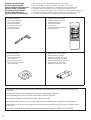
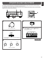
Indoor FM Antenna
●
Antenne FM intérieure
●
UKW-Innenantenne
●
FM inomhusantenn
●
Antenna FM per interni
●
Antena FM interior
●
FM Binnenantenne
●
AM Loop Antenna
●
Cadre-antenna AM
●
MW-Rahmenantenne
●
AM ramantenn
●
Antenna AM ad anello
●
Antena de cuadro de AM
●
AM Lusantenne
●
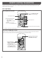
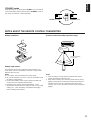
Remote Control Transmitter
●
Emetteur de télécommande
●
Fernbedienungsgeber
●
Fjärrkontrollsändare
●
Telecomando
●
Transmisor del control remoto
●
Afstandbediening
●
Batteries (size AA, R6, UM-3)
●
Piles (taille AA, R6, UM-3)
●
Batterien (Größe AA, R6, UM-3)
●
Batterier (storlek AA, R6, UM-3)
●
Batterie (dimensioni AA, R6, UM-3)
●
Pilas (tamaño AA, R6, UM-3)
●
Batterijen (maat AA, R6, UM-3)
SUPPLIED ACCESSORIES
●
After unpacking, check that the following parts are included.
ACCESSOIRES FOURNIS
●
Après le déballage, vérifier que les pièces suivantes sont incluses.
MITGELIEFERTE ZUBEHORTEILE
●
Nach dem Auspacken überprüfen, ob die folgenden Teile vorhanden sind.
MEDFOLJANDE TILLBEHOR
●
Kontrollera efter det apparaten packats upp att följande delar finns med.
ACCESSORI IN DOTAZIONE
●
Verificare che tutte le parti seguenti siano contenute nell’imballaggio dell’apparecchio.
ACCESORIOS INCLUIDOS
●
Desembale el aparato y verificar que los siguientes accesorios están en la caja.
BIJGELEVERDE ACCESSOIRES
●
Controleer na het uitpakken of de volgende onderdelen voorhanden zijn.

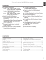
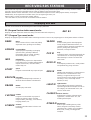
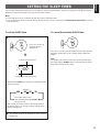
FEATURES
CONTENTS
3
English
●
5 Speaker Configuration
Front: 70W + 70W (8Ω) RMS Output
Power, 0.04% THD, 20–20,000 Hz
Center: 70W (8Ω) RMS Output Power,
0.07% THD, 1 kHz
Rear: 20W + 20W (8Ω) RMS Output
Power, 0.3% THD, 1 kHz
●
Digital Sound Field Processor
6 Programs for Digital Sound Field
Processing
2 Programs for Dolby Surround Decoding
(DOLBY PRO LOGIC and DOLBY PRO
LOGIC ENHANCED)
●
Automatic Input Balance Control for
Dolby Surround
●
Test Tone Generator for Easier Speaker
Output Balance Adjustment
●
3 Center Channel Modes
(NORMAL/WIDE/PHANTOM)
●
Multi-Functions for RDS Broadcast
Reception
●
40-Station Random Access Preset Tuning
●
Automatic Preset Tuning
●
Preset Station Shifting Capability (Preset
Editing)
●
IF Count Direct PLL Synthesizer Tuning
System
●
Video Signal Input/Output Capability
(Including S Video Connections)
●
SLEEP Timer
●
Remote Control Capability
Supplied Accessories ......................................2
Caution ............................................................4
Profile of This Unit ...........................................5
Speaker Setup for This Unit ............................6
Connections ....................................................7
Speaker Balance Adjustment ........................13
Basic Operations ...........................................16
Tuning Operations .........................................19
Preset Tuning ................................................20
Receiving RDS Stations ................................23
Using Digital Sound Field Processor (DSP)
......................................................................27
Setting the SLEEP Timer ..............................31
Remote Control Transmitter ..........................32
Notes about the Remote Control Transmitter
.......................................................................33
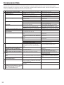
Troubleshooting .............................................34
Specifications ................................................35
Thank you for selecting this YAMAHA stereo receiver.

CAUTION : READ THIS BEFORE OPERATING YOUR UNIT.
4
1. To assure the finest performance, please read this manual
carefully. Keep it in a safe place for future reference.
2. Install this unit in a cool, dry, clean place – away from
windows, heat sources, sources of excessive vibration,
dust, moisture and cold. Avoid sources of humming
(transformers, motors). To prevent fire or electrical shock,
do not expose the unit to rain or water.
3. Never open the cabinet. If something drops into the set,
contact your dealer.
4. Do not use force on switches, controls or connection wires.
When moving the unit, first disconnect the power plug and
the wires connected to other equipment. Never pull the
wires themselves.
5. The openings on the cabinet assure proper ventilation of
the unit. If these openings are obstructed, the temperature
inside the cabinet will rise rapidly and eventually damage
the circuits. Therefore, avoid placing objects against these
openings and do not install the unit where the flow of air
through the ventilation openings could be impeded.
6. Always set the VOLUME control to “–
∞
” before starting
the audio source play. Increase the volume gradually to an
appropriate level after playback has been started.
7. Do not attempt to clean the unit with chemical solvents;
this might damage the finish. Use a clean, dry cloth.
8. Be sure to read the “TROUBLESHOOTING” section
regarding common operating errors before concluding that
the unit is faulty.
9. When not planning to use this unit for long periods of time
(ie., vacation, etc.), disconnect the AC power plug from the
wall outlet.
10.To prevent lightning damage, disconnect the AC power
plug and disconnect the antenna cable when there is an
electrical storm.
11.Grounding or polarization – Precautions should be taken
so that the grounding or polarization of an appliance is not
defeated.
12.AC outlet
Do not connect audio equipment to the AC outlet on the
rear panel if that equipment requires more power than the
outlet is rated to provide.
IMPORTANT
Please record the serial number of this unit in the space
below.
Serial No.:
The serial number is located on the rear of the unit.
Retain this Owner’s Manual in a safe place for future
reference.
WARNING
TO REDUCE THE RISK OF FIRE OR ELECTRIC SHOCK,
DO NOT EXPOSE THIS UNIT TO RAIN OR MOISTURE.
For U.K. customers
If the socket outlets in the home are not suitable for the plug
supplied with this appliance, it should be cut off and an
appropriate 3 pin plug fitted. For details, refer to the
instructions described below.
Note: The plug severed from the mains lead must be
destroyed, as a plug with bared flexible cord is hazardous if
engaged in a live socket outlet.
Special Instructions for U.K. Model
IMPORTANT
THE WIRES IN THE MAINS LEAD ARE COLOURED IN
ACCORDANCE WITH THE FOLLOWING CODE:
Blue: NEUTRAL
Brown: LIVE
As the colours of the wires in the main lead of this apparatus
may not correspond with the coloured markings identifying
the terminals in your plug, proceed as follows:
The wire which is coloured BLUE must be connected to the
terminal which is marked with the letter N or coloured
BLACK. The wire which is coloured BROWN must be
connected to the terminal which is marked with the letter L
or coloured RED. Make sure that neither core is connected
to the earth terminal of the three pin plug.
The apparatus is not disconnected from the AC power
source as long as it is connected to the wall outlet, even if
the apparatus itself is turned off.

5
English
PROFILE OF THIS UNIT
You are the proud owner of a Yamaha stereo receiver –an extremely sophisticated audio component. The Digital Sound Field
Processor (DSP) built into this unit takes full advantage of Yamaha’s undisputed leadership in the field of digital audio processing to
bring you a whole new world of listening experiences. Follow the instructions in this manual carefully when setting up your system,
and this unit will sonically transform your room into a wide range of listening environments –movie theater, concert hall, and so on.
In addition, you get incredible realism from Dolby-encoded video sources using the built-in Dolby Pro Logic Surround Decoder.
Please read this operation manual carefully and store it in a safe place for later reference.
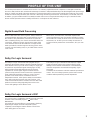
Digital Sound Field Processing
What is it that makes live music so good? Today’s advanced
sound reproduction technology lets you get extremely close to
the sound of a live performance, but chances are you’ll still
notice something missing: the acoustic environment of the live
concert hall. Extensive research into the exact nature of the
sonic reflections that create the ambience of a large hall has
made it possible for Yamaha engineers to bring you this same
sound in your own listening room, so you’ll feel all the sound of
a live concert.
What’s more, our technicians, armed with sophisticated
measuring equipment, have even made it possible to capture
the acoustics of a variety of venues such as an actual concert
hall, theater, etc. to allow you to accurately recreate one of
several actual live performance environments, all in your own
home.
Dolby Pro Logic Surround
The Dolby Pro Logic Surround Decoder program lets you
experience the dramatic realism and impact of Dolby Surround
movie theater sound in your own home. Dolby Pro Logic gets
its name from its professional-grade steering logic circuitry,
which provides greater effective front and rear channel
separation for a much higher degree of realism than the
“passive” Dolby Surround circuits found in less sophisticated
home audio/video equipment. Dolby Pro Logic Surround
provides a true center channel, so that there are four
independent channels, unlike passive Dolby Surround which
has in effect only three channels: left, right, and rear. This
center channel allows listeners seated in even less-than-ideal
positions to hear the dialog originating from action on the
screen while getting a stereo effect as well.
This Dolby Pro Logic Surround Decoder employs a digital
signal processing system. This system increases sound
stability at each channel and minimizes crosstalk between
channels compared to conventional analog Dolby signal
processing.
In addition, this unit features a built-in automatic input balance
control. This circuit always presents you the best surround
conditions without performing manual adjustments.
Dolby Pro Logic Surround + DSP
You can also enjoy a combination of Dolby Pro Logic Surround
and DSP in the sound field program “ PRO LOGIC
ENHANCED”.
It recreates the surround effect of a movie theater, effectively
duplicating its multiple surround loudspeaker system,
completely surrounding the listener with the sounds of the
action taking place on the screen.

6
SPEAKER SETUP FOR THIS UNIT
SPEAKERS TO BE USED
This unit is designed to provide the best sound-field quality with a 5 speaker configuration. The speakers to be used with this unit
will be mainly front speakers, rear speakers, and a center speaker. (You can omit the center speaker. Refer to the “4-Speaker
Configuration” shown below.)
The front speakers are used for the main source sound and the effect sound. They will probably be the speakers of your present
stereo speaker system. The rear speakers are used for the effect sound. And the center speaker is used for the center sound
(dialog etc.) encoded with the Dolby Surround. The rear and center speakers do not need to be equal in power to the front
speakers. However, all the speakers should have high enough power handling to accept the maximum output of this unit.
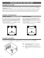
SPEAKER CONFIGURATION
5-Speaker Configuration
This configuration is the most effective and recommended one.
In this configuration, the center speaker is necessary as well as
the rear speakers. If the digital sound field program DOLBY
PRO LOGIC or DOLBY PRO LOGIC ENHANCED is selected,
conversations will be output from the center speaker and the
ambience will be excellent.
●
Set the center channel mode to the “NORMAL” or “WIDE”
position. (For details, refer to page 14.)
4-Speaker Configuration
The center speaker is not used in this configuration. If the
digital sound field program DOLBY PRO LOGIC or DOLBY
PRO LOGIC ENHANCED is selected, the center sound is
output from the left and the right front speakers. However, the
sound effect of other programs can be the same as that of the
5-speaker configuration.
●
Be sure to set the center channel mode to the “PHANTOM”
position. (For details, refer to page 14.)
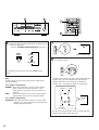
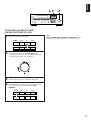
SPEAKER PLACEMENT
The recommended speaker configuration, the 5-speaker configuration, will require two speaker pairs: front speakers (your normal
stereo speakers), and rear speakers, plus a center speaker. When you place these speakers, refer to the following.
Front: In normal position. (The position of your present
stereo speaker system.)
Rear: Behind your listening position, facing slightly inward.
Nearly six feet (approx. 1.8 m) up from the floor.
Center: Precisely between the front speakers. (To avoid
interference with TV sets, use a magnetically shielded
speaker.)
Front L Center Front R
Dialogue
Surround sound
Dialogue
Surround sound
Rear L
Rear R
Front L Front R
Dialogue
Surround sound
Dialogue
Surround sound
Rear L Rear R
Front R
Center
Front L
TV set
Rear R
Rear L

7
English
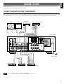
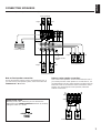
CONNECTIONS
Before attempting to make any connections to or from this unit, be sure to first switch OFF the power to this unit and to any other
components to which connections are being made.
CONNECTIONS WITH OTHER COMPONENTS
When making connections between this unit and other components, be sure all connections are made correctly, that is to say L (left)
to L, R (right) to R, “+” to “+” and “–” to “–”. Also, refer to the owner’s manual for each component to be connected to this unit.
:Refer to “ABOUT THE ACCESSORY TERMINALS” on page 11.
GND
MONITOR
OUT
S VIDEO
IN OUT
VCR 2
MONITOR
OUT
LD/TV
IN OUT
VCR 1
IN OUT
VCR 2
PHONO CD TAPE LD/TV VCR 1 VCR 2
TAPE
PB
REC
OUT
IN OUT IN OUT
A OR B:8
Ω
MIN.
/SPEAKER
A B:l6
Ω
MIN.
/SPEAKER
FRONT
C D:4ΩMIN./SPEAKER
SINGLE:8ΩMIN./SPEAKER
8
Ω
MIN.
/SPEAKER
REAR
CENTER
CD
DUAL
SINGLE
FRONT CENTER REAR
SWITCHED
l20W MAX. TOTAL
VIDEO SIGNAL
AUDIO SIGNAL
SPEAKERS
SPEAKERS
OUTPUT
AC OUTLETS
A
B
A
B
l0 dB 0 dB
-
FRONT
LEVEL
FM
ANT
AM
ANT
GND
75
Ω
UNBAL.
fc:200Hz
LOW
PASS
MAINS
OUTPUT
GND
VIDEO IN
AUDIO OUT
VIDEO OUT
VIDEO OUT
AUDIO OUT
VIDEO IN
AUDIO IN
OUTPUT
LINE OUT
LINE IN
VIDEO OUT
AUDIO OUT
AUDIO IN
VIDEO IN
(Europe model)
To AC outlet
Turntable Monitor TV
LD player,
TV tuner, etc. Video cassette recorder 2
CD player Tape deck Video cassette recorder 1

8
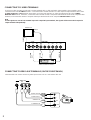
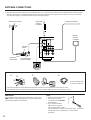
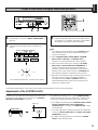
CONNECTING TO S VIDEO TERMINALS
If you have a video cassette recorder and a monitor equipped with “S” (high-resolution) video terminals, those terminals can be
connected to this unit’s S VIDEO terminals. Connect the video cassette recorder’s “S” video input and output terminals to this unit’s
S VIDEO VCR 2 IN and OUT terminals respectively, and connect the monitor’s “S” video input terminal to this unit’s S VIDEO
MONITOR OUT terminal. Otherwise, connect the video cassette recorder’s composite video terminals to this unit’s composite video
terminals, and connect the monitor’s composite video input terminal to this unit’s composite MONITOR OUT terminal.
Note
If video signals are sent to both S VIDEO input and composite input terminals, the signals will be sent to their respective
output terminals independently.
CONNECTING TO VIDEO AUX TERMINALS (ON THE FRONT PANEL)
These terminals are used to connect any video input source such as a camcorder to this unit.
MONITOR
OUT
S VIDEO
IN OUT
VCR 2
MONITOR
OUT
LD/TV
IN OUT
VCR 1
IN OUT
VCR 2
VIDEO SIGNAL
S VIDEO
IN
VIDEO
IN
S VIDEO
OUT
S VIDEO
IN
VIDEO OUT
VIDEO IN
Monitor TV
VIDEO AUX
S VIDEO VIDEO L AUDIO R
S VIDEO
L
R
VIDEO
Video cassette recorder 2
Camcorder
AUDIO OUT R
AUDIO OUT L
VIDEO OUT
S VIDEO OUT

9
English
CONNECTING SPEAKERS
A OR B:8
Ω
MIN.
/SPEAKER
A B:l6
Ω
MIN.
/SPEAKER
FRONT
C D:4
Ω
MIN./SPEAKER
SINGLE:8ΩMIN./SPEAKER
8
Ω
MIN.
/SPEAKER
REAR
CENTER
FRONT CENTER REAR
SPEAKERS
SPEAKERS
OUTPUT
A
B
A
B
l0 dB 0 dB
-
FRONT
LEVEL
fc:200Hz
LOW
PASS
CD
DUAL
SINGLE
Connect the respective speakers to this unit as figured below.
Note on front speaker connection:
One or two speaker systems can be connected to this unit. If
you connect only one speaker system, connect it to either the
SPEAKERS A or B terminals.
FRONT LEVEL switch
Normally set to “0 dB”. If desired, you can decrease the
output level at the FRONT SPEAKERS terminals by 10 dB by
setting this switch to “–10 dB”.
Note on center speaker connection:
One or two center speakers can be connected to this unit. If
you cannot place the center speaker on or under the TV, it is
recommended to use two center speakers and place them on
both sides of the TV to orient the center sound at the center
position. For connecting two center speakers, follow the
method shown below.
Rear speakers
Center speaker
FRONT LEVEL
switch
Front speakers B
Left
Right
Left
Right
Center speaker
Center speaker
Front speakers A
Left
Right
l0 dB 0 dB
FRONT
LEVEL
l
REAR
CENTER
CD
DUAL
SINGLE

10
How to Connect:
Connect the SPEAKERS terminals to your speakers with wire
of the proper gauge, cut as short as possible. If the
connections are faulty, no sound will be heard from the
speakers. Make sure that the polarity of the speaker wires is
correct, that is, + and – markings are observed. If these wires
are reversed, the sound will be unnatural and will lack bass.
Do not let the bare speaker wires touch each other and do
not let them touch the metal parts of this unit as this could
damage this unit and/or speakers.
Note
Use speakers with the specified impedance shown on the rear
of this unit.
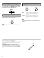
For connecting to the FRONT SPEAKERS terminals
Red: positive (+)
Black: negative (–)
➀
Unscrew the knob.
➁
Insert the bare wire.
[Remove approx. 5mm
(1/4”) insulation from
the speaker wires.]
➂
Tighten the knob and
secure the wire.
For connecting to the REAR and CENTER SPEAKERS
terminals
Red: positive (+)
Black: negative (–)
➀
Press up the tab.
➁
Insert the bare wire.
[Remove approx. 5mm
(1/4”) insulation from
the speaker wires.]
➂
Release down the tab
and secure the wire.
➁
➂
➀
1
2
3

11
English
Subwoofer system
ABOUT THE ACCESSORY TERMINALS
AC OUTLET(S) (SWITCHED)
(Europe model) ................................. 2 SWITCHED OUTLETS
(U.K. model) ........................................ 1 SWITCHED OUTLET
Use these to connect the power cords from your components
to this unit.
The power to the SWITCHED outlets is controlled by this unit’s
POWER switch or the provided remote control transmitter’s
POWER key. These outlets will supply power to any
component whenever this unit is turned on.
The maximum power (total power consumption of
components) that can be connected to the SWITCHED AC
OUTLET(S) is 120 watts.
GND terminal (For turntable use)
Connecting the ground wire of the turntable to this terminal will
normally minimize hum, but in some cases better results may
be obtained with the ground wire disconnected.
LOW PASS terminal
This terminal is for output to a monaural amplifier driving a
subwoofer. Only frequencies below 200 Hz from the front and
center channels are output.
ADDING A SUBWOOFER
You may wish to add a subwoofer to reinforce the bass
frequencies.
Connect the LOW PASS terminal to the INPUT terminal of
the subwoofer amplifier, and connect the speaker terminals
of the subwoofer amplifier to the subwoofer.
With some subwoofers, including the Yamaha Active Servo
Processing Subwoofer System, the amplifier and subwoofer
are in the same unit.
FRONT OUTPUT terminals
These terminals are for front channel line output. There is no
connection to these terminals when you use the built-in
amplifier.
However, if you drive front speakers with an external stereo
power amplifier, connect the input terminals of the external
amplifier (MAIN IN or AUX terminals of a power amplifier or an
integrated amplifier) to these terminals.
REAR OUTPUT terminals
These terminals are for rear channel line output. There is no
connection to these terminals when you use the built-in
amplifier.
However, if you drive rear speakers with an external stereo
power amplifier, connect the input terminals of the external
amplifier (MAIN IN or AUX terminals of a power amplifier or an
integrated amplifier) to these terminals.
CENTER OUTPUT terminal
This terminal is for center channel line output. There is no
connection to this terminal when you use the built-in amplifier.
However, if you drive a center speaker with an external power
amplifier, connect the input terminal of the external amplifier to
this terminal.
FRONT CENTER REAR
OUTPUT
fc:200Hz
LOW
PASS

12
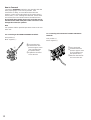
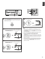
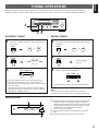
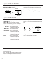
ANTENNA CONNECTIONS
●
Each antenna should be connected to the designated terminals correctly, referring to the following diagram.
●
Both AM and FM indoor antennas are included with this unit. In general, these antennas will probably provide sufficient signal
strength. Nevertheless, a properly installed outdoor antenna will give clearer reception than an indoor one. If you experience
poor reception quality, an outdoor antenna may result in improvement.
Connecting the AM loop antenna
* The AM loop antenna should be placed apart from the main unit. The antenna may be hung on a wall.
* The AM loop antenna should be kept connected, even if an outdoor AM antenna is connected to this unit.
GND terminal
For maximum safety and minimum interference, connect the
GND terminal to a good earth ground. A good earth ground is
a metal stake driven into moist earth.
Notes
●
When connecting the indoor
FM antenna, insert its
connector into the FM ANT
terminal firmly.
●
If you need an outdoor
FM antenna to improve
FM reception quality, either
300-ohm feeder or coaxial cable may be used. In locations
troubled by electrical interference, coaxial cable is
preferable.
Outdoor FM antenna
Outdoor AM antenna
AM loop
antenna
(included)
Ground
Indoor FM
antenna
(included)
75-ohm/300-ohm
antenna adapter
75-ohm
coaxial cable
300-ohm
feeder
GND
MONITOR
OUT
S VIDEO
IN OUT
VCR 2
PHONO CD
TAPE
PB
FM
ANT
AM
ANT
GND
75
Ω
UNBAL.
➀
➁
➂
Orient so that the best
reception is obtained.
12 3

1
Set to the “
∞
” position.
2 Select the front speakers to be used.
* If you use two front speaker systems, press both the A
and B switches.
3
Set to the “0” position.
4
5 Select the PRO LOGIC or PRO LOGIC
ENHANCED mode, so that the corresponding name is
illuminated on the display.
13
English
SPEAKER BALANCE ADJUSTMENT
This procedure lets you adjust the sound output level balance between the front, center, and rear speakers using the built-in test
tone generator. With this adjustment, the sound output level heard at the listening position will be the same from each speaker.
This is important for the best performance of the digital sound field processor.
The adjustment of each speaker output level should be done at your listening position with the remote control transmitter.
Otherwise, the result may not be satisfactory.
5
1
4
2
3
SPEAKERS
A
B
ON
OFF
ON
OFF
BASS
55
4
3
2
l
0
l
2
3
4
TREBLE
55
4
3
2
l
0
l
2
3
4
BALANCE
55
4
3
2
l
0
l
2
3
4
LR
POWER
TAPE MON
DIR BPLAYDIR A
REC PAUSE
LD/TVSTOPTEST
VCR 1
CNCT VIDEOENHANCED
PRO LOGIC
VCR 2DISCO
STADIUM
MONO MOVIE
CENTER
LEVEL
V AUX
EFFECT
ON/OFF
HALLROCK
VOLUME
REAR
LEVEL
SUR.
DELAY TIME
5
CONTINUED
DISCO
ROCK
CONCERT
CONCERT
HALL
PRO LOGIC
ENHANCED
CONCERT
VIDEO
MONO
MOVIE
STADIUM
DIGITAL SOUND FIELD PROCESSOR
EFFECT

6 Select the center channel output mode according to your
speaker configuration.
(Refer to “SPEAKER CONFIGURATION” on page 6.)
On the feature of each mode, refer to the “Note” shown
below.
7
8 Turn up the volume.
You will hear a test tone (like pink noise) from the left front
speaker, then the center speaker, then the right front
speaker, and then the rear speakers, for about two
seconds each. The display changes as shown below.
* The test tone from the left rear speaker and the right rear
speaker will be heard at the same time.
14
Note
In step 6, when you select the center channel output mode,
note the following.
For 5 speaker configuration)
NORMAL: Select this mode when you use a center speaker
that is smaller than the front speakers. In this
mode, the bass tone will be output from the front
speakers.
WIDE: Select this mode when you use the center speaker
approximately same sized as the front speakers.
For 4 speaker configuration)
PHANTOM: Select this mode when you do not use the center
speaker. The center sound will be output from the
left and right front speakers.
Flashes continuously.
VOLUME
CENTER
MODE
TEST
ER
TEST
NORMAL
WIDE
PHANTOM
TEST
Front (L) Center
Rear
(L and R)
Front (R)
TAPE MON
DIR BPLAYDIR A
REC PAUSE
LD/TVSTOPTEST
VCR 1
CNCT VIDEOENHANCED
PRO LOGIC
VCR 2DISCO
STADIUM
MONO MOVIE
CENTER
LEVEL
V AUX
EFFECT
ON/OFF
HALLROCK
VOLUME
REAR
LEVEL
SUR.
DELAY TIME
7
8
8
6

9 Adjust the BALANCE control so that the effect sound
output level of the left front speaker and the right front
speaker are the same.
10 Adjust the sound output level of the center speaker to
be at the same level as that of the front speakers with
the CENTER LEVEL keys.
11 Adjust the sound output level of the rear speakers to
be at the same level as that of the front speakers with
the REAR LEVEL keys.
12 Cancel the test tone.
Stops flashing and disappears
Notes
●
Once you have completed these adjustments, you can
adjust whole sound level on your audio system by using
the VOLUME control (or the VOLUME keys on the remote
control transmitter).
●
If you use external power amplifiers, their volume controls
may also be adjusted to achieve proper balance.
●
In step 10, if the center channel mode is in the
“PHANTOM” position, the sound output level of the center
speaker cannot be adjusted. This is because in this mode,
the center sound is automatically output from the left and
right front speakers.
●
If there is insufficient sound output from the center and
rear speakers, you may decrease the front speaker output
level by setting the FRONT LEVEL switch on the rear
panel to “–10 dB”.
15
English
BALANCE
55
4
3
2
l
0
l
2
3
4
LR
9
12
10
11
CENTER
LEVEL
00
CENTER
TEST
REAR
LEVEL
0
REAR
TEST
TEST
R
TEST
Lights up.
Adjustable
TAPE MON
DIR BPLAYDIR A
REC PAUSE
LD/TVSTOPTEST
VCR 1
CNCT VIDEOENHANCED
PRO LOGIC
VCR 2DISCO
STADIUM
MONO MOVIE
CENTER
LEVEL
V AUX
EFFECT
ON/OFF
HALLROCK
VOLUME
REAR
LEVEL
SUR.
DELAY TIME
Lights up.
Adjustable

1
Set to the “
∞
” position.
2
3 Select the desired input source by using the input
selector buttons.
(For video sources, turn the TV/monitor ON.)
* The name of the selected input source will appear in
the display.
4 Select the front speakers to be used.
* If you use two front speaker systems, press both the A and
B switches.
5 Play the source. (For detailed information on the
tuning operation, refer to page 19.)
6
Adjust to the desired output level.
7 If desired, adjust the BASS, TREBLE, BALANCE
controls, etc. (refer to page 18) and use the digital
sound field processor. (Refer to page 29.)
Notes on using the input selector buttons
●
Note that pressing on each input selector button selects
the source which is connected to the corresponding input
terminals on the rear panel.
* To select the source connected to the VIDEO AUX
terminals on the front panel, press VIDEO AUX.
●
The selection of TAPE MONITOR cannot be canceled by
pressing another input selector button. To cancel it, press
TAPE MONITOR again.
When you select a button other than TAPE MONITOR,
make sure that TAPE MONITOR is not also selected.
●
If you select the input selector button for a video source
without canceling the selection of TAPE MONITOR, the
playback result will be the video image from the video
source and the sound from the audio tape.
●
Once you play a video source, its video image will not be
interrupted even if the input selector button for an audio
source is selected.
To turn off the power
Press the POWER switch again.
16
BASIC OPERATIONS
TO PLAY A SOURCE
SPEAKERS
A
B
ON
OFF
ON
OFF
VIDEO AUX VCR 2 VCR 1 LD/TV
TAPE
MONITOR
TUNER CD PHONO
3
1, 6
2
4
7
7
POWER

1 Select the source to be recorded.
2
Play the source and then turn the VOLUME control
up to confirm the input source. (For detailed information
on the tuning operations, refer to page 19.)
3 Set the tape deck or VCR to the recording mode.
4 If the tape deck is used for recording, you can monitor
the sounds being recorded by pressing TAPE
MONITOR.
Note
DSP, VOLUME, BASS, TREBLE and BALANCE control
settings have no effect on the material being recorded.
17
English
TO RECORD A SOURCE TO TAPE
(OR DUB FROM TAPE TO TAPE)
VIDEO AUX VCR 2 VCR 1 LD/TV
TAPE
MONITOR
TUNER CD PHONO
VIDEO AUX VCR 2 VCR 1 LD/TV
TAPE
MONITOR
TUNER CD PHONO
1, 4
2

18
Because one or two speaker systems (as front speakers) can
be connected to this unit, the SPEAKERS switches allow you
to select speaker system A or B, or both at once.
Adjust the balance of the output volume to the left and right
speakers to compensate for sound imbalance caused by
speaker location or listening room conditions.
Note
This control is effective only for the sound from the front
speakers.
BASS : Turn this clockwise to increase (or counter-
clockwise to decrease) the low frequency
response.
TREBLE : Turn this clockwise to increase (or counter-
clockwise to decrease) the high frequency
response.
Note
These controls are effective only for the sound from the front
speakers.
When you listen with headphones
Connect the headphones to the PHONES jack. You can listen
to the sound to be output from the front speakers through
headphones.
When listening with headphones privately, set both the
SPEAKERS A and B switches to the OFF position and switch
off the digital sound field processor (so that no DSP program
name is illuminated on the display) by pressing the EFFECT
switch.
Selecting the SPEAKER system
Adjusting the BASS and TREBLE
controls
Adjusting the BALANCE control
PHONES
SPEAKERS
A
B
ON
OFF
ON
OFF
BALANCE
55
4
3
2
l
0
l
2
3
4
LR
TREBLE
55
4
3
2
l
0
l
2
3
4
BASS
55
4
3
2
l
0
l
2
3
4

19
English
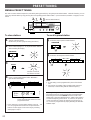
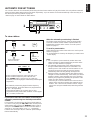
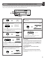
1 Select the reception band (FM or AM) while watching
the display.
2
3 Tune to a desired station manually.
* To continue tuning search, press and hold the button.
FM/AM
FM AM
or
1 Select the reception band (FM or AM) while watching
the display.
2
3
To tune to a higher frequency, press the right side once.
To tune to a lower frequency, press the left side once.
* If the station where tuning search stops is not the desired
one, press again.
* If the tuning search does not stop at the desired station
(because the signals of the station are weak), change to
the MANUAL TUNING method.
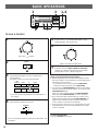
TUNING OPERATIONS
Normally, if station signals are strong and there is no interference, quick automatic-search tuning (AUTOMATIC TUNING) is
possible. However, if signals of the station you want to select are weak, you must tune to it manually (MANUAL TUNING).
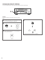
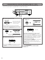
Display information
➀
Displays the band and frequency of the received station.
* If an RDS station is received, the frequency is then
replaced by the station name. (However, if the PS data
cannot be received within 5 seconds, “NO PS” flashes,
and then it returns to the frequency display.)
Refer to page 24 for details.
➁
Lights up when an FM stereo broadcast is received in
stereo.
➂
Indicates the signal level of the received station.
Note
If you tune to an FM station manually, it is received in
monaural mode automatically to increase the signal quality.
AUTOMATIC TUNING MANUAL TUNING
FM/AM
TUNING
MODE
AUTO/MAN’L MONO
TUNING
MODE
AUTO/MAN’L MONO
DOWN
TUNING UP
DOWN
TUNING UP
PRESET
MHz
FM
STEREO
0
20
l00
REAR
➀➁
➂
AUTO TUNING
“AUTO TUNING”
goes off.
FM AM
or
1 3
2

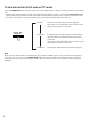
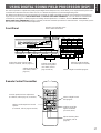
1 Tune to a desired station.
(Refer to the previous page for tuning procedure.)
2 Select a desired page (A – E) of preset station buttons
while watching the display.
3
4 Press a preset station button before “MEMORY”
goes off from the display.
* In the same way, program other stations to A2, A3 ... A8.
* You can program more stations to the preset station
buttons on other pages in the same way by selecting
other pages in step 2.
11 Select the page of preset station buttons.
22 Select the desired preset station button.
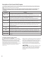
Notes
●
A new setting can be programmed in place of the former
one.
●
For presets, the setting of the reception mode (stereo or
monaural) is stored along with the station frequency.
Memory back-up
The memory back-up circuit prevents the programmed data
from being lost even if the POWER switch is set off or the
power plug is disconnected from the AC outlet or the power is
cut due to temporary power failure. If, however, the power is
cut for more than one week, the memory may be erased. If
so, it can be re-programmed by simply following the PRESET
TUNING steps.
20
MANUAL PRESET TUNING
This unit can store station frequencies (selected by tuning operation) by using the preset station buttons. With this function, you can
select any desired station by only pressing the corresponding preset station button. Up to 40 stations (8 stations x 5 pages) can be
stored.
PRESET TUNING
To store stations
To recall a preset station
3
2, 11
4, 22 (Preset station buttons)
A/B/C/D/E
PRESET
MEMORY
MAN’L/AUTO FM
MEMORY
A/B/C/D/E
PRESET
Flashes on and off
for about 5 seconds.
l 2345 67 8
PRESET STATIONS
l 2345 67 8
PRESET STATIONS
PRESET
MHz
FM
STEREO
0
20
l00
REAR
AUTO TUNING
Shows the displayed station has been
programmed to A1.
PRESET
A página está carregando...
A página está carregando...
A página está carregando...
A página está carregando...
A página está carregando...
A página está carregando...
A página está carregando...
A página está carregando...
A página está carregando...
A página está carregando...
A página está carregando...
A página está carregando...
A página está carregando...
A página está carregando...
A página está carregando...
A página está carregando...
-
 1
1
-
 2
2
-
 3
3
-
 4
4
-
 5
5
-
 6
6
-
 7
7
-
 8
8
-
 9
9
-
 10
10
-
 11
11
-
 12
12
-
 13
13
-
 14
14
-
 15
15
-
 16
16
-
 17
17
-
 18
18
-
 19
19
-
 20
20
-
 21
21
-
 22
22
-
 23
23
-
 24
24
-
 25
25
-
 26
26
-
 27
27
-
 28
28
-
 29
29
-
 30
30
-
 31
31
-
 32
32
-
 33
33
-
 34
34
-
 35
35
-
 36
36


Yamaha RX-V590RDS Manual do usuário
- Categoria
- Receptor
- Tipo
- Manual do usuário
em outras línguas
- español: Yamaha RX-V590RDS Manual de usuario
- français: Yamaha RX-V590RDS Manuel utilisateur
- italiano: Yamaha RX-V590RDS Manuale utente
- English: Yamaha RX-V590RDS User manual
- русский: Yamaha RX-V590RDS Руководство пользователя
- Nederlands: Yamaha RX-V590RDS Handleiding
- Deutsch: Yamaha RX-V590RDS Benutzerhandbuch
- dansk: Yamaha RX-V590RDS Brugermanual
- čeština: Yamaha RX-V590RDS Uživatelský manuál
- svenska: Yamaha RX-V590RDS Användarmanual
- polski: Yamaha RX-V590RDS Instrukcja obsługi
- Türkçe: Yamaha RX-V590RDS Kullanım kılavuzu
- suomi: Yamaha RX-V590RDS Ohjekirja
- română: Yamaha RX-V590RDS Manual de utilizare