Sony Ericsson XR-C7500RX Manual do usuário
- Categoria
- Toca-fitas
- Tipo
- Manual do usuário

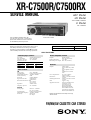
SERVICE MANUAL
FM/MW/LW CASSETTE CAR STEREO
AEP Model
UK Model
XR-C7500R/C7500RX
E Model
XR-C7500RX
Model Name Using Similar Mechanism XR-C7300/C5300R
Tape Transport Mechanism Type MG-25G-136
SPECIFICATIONS
XR-C7500R/C7500RX
Dolby noise reduction manufactured under license
from Dolby Laboratories Licensing Corporation.
“DOLBY” and the double-D symbol ; are trade-
marks of Dolby Laboratories Licensing Corporation.
Photo: XR-C7500R
General
Outputs Audio output
Power aerial relay control
lead
Power amplifier control
lead
Telephone ATT control
lead
Power requirements 12 V DC car battery
(negative earth)
Dimensions Approx. 178 × 50 × 183 mm
(w/h/d)
Mounting dimensions Approx. 182 × 53 × 162 mm
(w/h/d)
Mass Approx. 1.2 kg
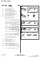
Supplied accessories Parts for installation and
connections (1 set)
Front panel case (1)
Rotary commander
RM-X4S (XR-C7500R/
XR-C7500RX: AEP, UK)
Card remote commander
RM-X91 (XR-C7500RX: E)
Design and specifications are subject to change
without notice.
Cassette player section
Tape track 4-track 2-channel stereo
Wow and flutter 0.08 % (WRMS)
Frequency response 30 – 18,000 Hz
Signal-to-noise ratio
Tuner section
FM
Tuning range 87.5 – 108.0 MHz
Aerial terminal External aerial connector
Intermediate frequency 10.7 MHz/450 kHz
Usable sensitivity 8 dBf
Selectivity 75 dB at 400 kHz
Signal-to-noise ratio 66 dB (stereo),
72 dB (mono)
Harmonic distortion at 1 kHz
0.6 % (stereo),
0.3 % (mono)
Separation 35 dB at 1 kHz
Frequency response 30 – 15,000 Hz
MW/LW
Tuning range MW: 531 – 1,602 kHz
LW: 153 – 279 kHz
Aerial terminal External aerial connector
Intermediate frequency 10.7 MHz/450 kHz
Sensitivity MW: 30 µV
LW: 40 µV
Power amplifier section
Outputs Speaker outputs
(sure seal connectors)
Speaker impedance 4 – 8 ohms
Maximum power output 50 W × 4 (at 4 ohms)
Cassette type
TYPE II, IV
TYPE I
Dolby NR off
61 dB
58 dB
Dolby B NR
67 dB
64 dB
(XR-C7500R/C7500RX: AEP, UK)
For RM-X4S (Remote Commander),
please refer to RM-X4S Service Manual
(9-925-698-S) previously issued.

2
TABLE OF CONTENTS
1. SERVICING NOTES ............................................... 2
2. GENERAL
Location of Controls ....................................................... 3
Setting the Clock ............................................................. 3
Installation....................................................................... 4
Connections ..................................................................... 6
3. DISASSEMBLY ......................................................... 10
4. ASSEMBLY OF MECHANISM DECK........... 12
5. MECHANICAL ADJUSTMENTS ....................... 15
6. ELECTRICAL ADJUSTMENTS
Test Mode ........................................................................ 15
Tape Deck Section .......................................................... 16
Tuner Section .................................................................. 16
7. DIAGRAMS
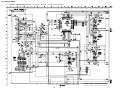
7-1. Block Diagram – TUNER/TAPE Section – ................... 17
7-2. Block Diagram – MAIN Section – ................................. 18
7-3. Block Diagram
– DISPLAY/KEY CONTROL Section –........................ 19
7-4. Block Diagram
– BUS CONTROL/POWER SUPPLY Section – ........... 20
7-5. Note for Printed Wiring Boards and
Schematic Diagrams ....................................................... 21
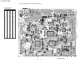
7-6. Printed Wiring Board
– Main Board (Component Side) – ................................ 22
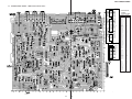
7-7. Printed Wiring Board
– Main Board (Conductor Side) – .................................. 23
7-8. Schematic Diagram – Main Board (1/4) – ..................... 24
7-9. Schematic Diagram – Main Board (2/4) – ..................... 25
7-10. Schematic Diagram – Main Board (3/4) – ..................... 26
7-11. Schematic Diagram – Main Board (4/4) – ..................... 27
7-12. Printed Wiring Board – SUB Board – ........................... 28
7-13. Schematic Diagram – SUB Board – ............................... 28
7-14. Printed Wiring Board – KEY Board –........................... 30
7-15. Schematic Diagram – KEY Board – .............................. 31
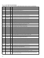
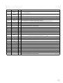
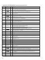
7-16. IC Pin Function Description ........................................... 34
8. EXPLODED VIEWS ................................................ 40
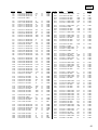
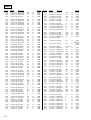
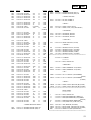
9. ELECTRICAL PARTS LIST ............................... 43
Notes on chip component replacement
• Never reuse a disconnected chip component.
• Notice that the minus side of a tantalum capacitor may be dam-
aged by heat.
Flexible Circuit Board Repairing
• Keep the temperature of the soldering iron around 270 ˚C dur-
ing repairing.
• Do not touch the soldering iron on the same conductor of the
circuit board (within 3 times).
• Be careful not to apply force on the conductor when soldering
or unsoldering.
SECTION 1
SERVICING NOTES
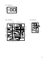
MODEL IDENTIFICATION
The XR-C7500R and XR-C7500RX have three types of MAIN
boards respectively.
TUX1
R606
R607
CN201
– MAIN BOARD (Conductor Side) –
TYPE A TYPE B TYPE C
R606 × aa
R607 a × a

3
SECTION 2
GENERAL
This section is extracted from
instruction manual.
5
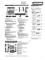
Location of controls
1 MENU button
9, 11, 12, 13, 15, 17, 18, 20, 21, 23, 24,
26, 27, 30, 31, 33, 34, 35
2 Volume control dial
3 SOURCE (TUNER/TAPE/CD/MD) button
6, 8, 10, 12, 13, 19, 20, 24, 25, 26, 27, 31,
34
4 PRST/DISC +/– (cursor up/down) buttons
8, 9, 11, 12, 13, 15, 17, 18, 19, 20, 21, 22,
23, 24, 26, 27, 30, 31, 32, 33, 34, 35
During radio reception:
Preset stations select 13
During CD/MD playback:
Disc change 32
5 DSPL/PTY (display mode change/
programme type) button
11, 18, 23, 31, 33
6 LIST button
Disc memo 33
List-up 22, 34
7 Display window
8
Z (eject) button (located on the front side
of the unit behind the front panel)
10
9 OPEN button 7, 10, 36
q; DSO button 26
qa SOUND button 24, 25, 26
qs OFF button* 6, 7, 8, 10
qd Reset button (located on the front side
of the unit behind the front panel) 7
qf SEEK/AMS –/+ (cursor left/right) buttons
8, 9, 10, 11, 12, 13, 15, 17, 18, 19, 21, 23,
24, 25, 26, 27, 30, 31, 32, 33, 35
Seek 13, 15, 19
Automatic Music Sensor 10, 32
Manual search 13, 32
XR-C7500RX/XR-C7500R
D
I
S
C
+
P
R
S
T
+
D
I
S
C
–
P
R
S
T
-
SOURCE
DSPL
LIST
AF
OFF
PTY
ENTER
MENU
SOUND
1 2 3 4 56
-
SEEK/AMS
REP SHUF
TA
OPEN
MODE
DSO
qg ENTER button
9, 11, 12, 13, 15, 17, 18, 20, 21, 22, 23,
24, 26, 27, 30, 31, 33, 34, 35
qh MODE button 10, 11, 12, 13, 19, 20, 31,
34
During tape playback:
Playback direction change 10
During radio reception:
BAND select 12, 13
During CD/MD playback:
CD/MD unit select 31
qj Receptor for the card remote
commander
qk Number buttons
During radio reception:
Preset number select
12, 13, 16, 17, 20, 21
During tape playback:
(1) REP 11
During CD/MD playback:
(1) REP 32
(2) SHUF 32
ql AF button 15, 17
w; TA button 16, 17
* Warning when installing in a car
without ACC (accessory) position on
the ignition key switch
Be sure to press (OFF) on the unit for two
seconds to turn off the clock display after
turning off the engine.
When you press (OFF) only momentarily,
the clock display does not turn off and this
causes battery wear.
Refer to the pages listed for details.
2
Press (ENTER).
The clock starts.
After the clock setting is complete, the
display returns to normal playback mode.
Tips
• You can use the convenient CT function to set
the clock automatically (page 18).
• When the D.Info mode is set to on, the time is
always displayed (page 30).
Setting the clock
The clock uses a 24-hour digital indication.
Example: To set the clock to 10:08
1
Press (MENU), then press either side of
(PRST/DISC) repeatedly until “Clock”
appears.
1 Press (ENTER).
The hour indication flashes.
2 Press either side of (PRST/DISC) to set
the hour.
3 Press (+) side of (SEEK/AMS).
The minute indication flashes.
4 Press either side of (PRST/DISC) to set
the minute.
A unit turned off by pressing (OFF) for two seconds cannot be operated with the card remote
commander unless (SOURCE) on the unit is
p
ressed or a casette is inserted to activate the unit first.
Card remote commander RM-X91
The corresponding buttons of the card
remote commander control the same
functions as those on this unit.
1 OFF button
2 MENU button
3 SOURCE button
4 SEEK/AMS (cursor </,) buttons
5 SOUND button
6 DSPL/PTY button
7 ATT button
8 LIST button
9 DISC/PRST (cursor M/m) buttons
q; ENTER button
qa MODE button
qs VOL buttons
OFF
SEEK SEEK
OPEN/CLOSE
MENU LIST
SOUND
ENTER
DISC
DISC
SOURCE
DSPL MODE
VO LAT T
(XR-C7500RX: E)

4
15
cm
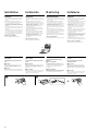
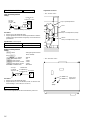
Installation
Precautions
•If you mount other Sony equipment with this
unit, it is better to mount this unit in the lower
position.
•There must be a distance of at least 15 cm
between the cassettes slot of the unit and shift
lever to insert cassette easily. Choose the
installation location carefully so the unit does
not interfere with gear shifting and other driving
operations.
•Choose the installation location carefully so that
the unit will not interfere with normal driving
operations.
•Avoid installing the unit in areas subject to dust,
dirt, excessive vibration, or high temperatures,
such as in direct sunlight or near heater ducts.
•Use only the supplied mounting hardware for a
safe and secure installation.
Mounting angle adjustment
Adjust the mounting angle to less than 20°.
Instalación
Precauciones
•Si monta otro equipo Sony con esta unidad, es
preferible montar esta unidad en la posición más
baja.
•Para que sea posible insertar la cinta con
facilidad, debe haber una distancia de al menos
15 cm entre la ranura de inserción de cintas de la
unidad y la palanca de cambios.
Instale la unidad en un lugar que no entorpezca
las operaciones de cambio de marchas o de
conducción en general.
•Elija cuidadosamente el lugar de montaje de
forma que la unidad no dificulte las funciones
normales de conducción.
•Evite instalar la unidad donde pueda quedar
sometida a altas temperaturas, como a la luz
solar directa o al aire de calefacción, o a polvo,
suciedad o vibraciones excesivas.
•Para realizar una instalación segura y firme,
utilice solamente la ferretería de montaje
suministrada.
Ajuste del ángulo de montaje
Ajuste el ángulo de montaje a menos de 20°.
Montering
Säkerhetsföreskrifter
•Om du monterar annan Sony-utrustning till
denna enhet är det bäst att montera denna enhet
i det undre läget.
•För att du ska kunna sätta i och ta ut bandet
måste avståndet vara minst 15 cm mellan
kassettfacket på enheten och växelspaken. När
du installerar enheten väljer du en plats så att
enheten inte är i vägen när du kör.
•Var noga när du väljer var i bilen du monterar
bilstereon, så att den inte sitter i vägen när du
kör.
•Montera inte bilstereon där den utsätts för
värme, t ex solsken eller varmluft, eller där den
utsätts för damm, smuts och/eller vibrationer.
•Använd endast de medföljande
monteringstillbehören för att vara säker på att
bilstereon monteras på ett säkert och korrekt
sätt.
Tillåten monteringsvinkel
Monteringsvinkeln får inte vara större än 20 grader.
Instalação
Precauções
•É preferível montar este aparelho na posição
mais baixa, se quiser montar simultaneamente
outros equipamentos da Sony.
•Para colocar com facilidade a cassete, deve haver
uma distância de pelo menos 15 cm entre a
ranhura de introduçäo da cassete e a alavanca
das mudanças.
Escolha o local de instalaçäo de forma a que o
aparelho näo interfira com as mudanças de
velocidade ou com as outras manobras de
conduçäo.
•Escolha com cuidado um local apropriado para
a montagem do aparelho, para que este não
interfira com as manobras necessárias à
condução do veículo.
•Evite instalar o aparelho onde possa estar sujeito
a altas temperaturas, como em locais expostos
directamente à luz do sol, ao ar quente dos
aquecimentos, ou sujeitos a pó, sujidade ou
vibração excessiva.
•Para efectuar uma instalação segura utilize
unicamente o hardware de montagem fornecido.
Ajuste do ângulo de montagem
Ajuste o ângulo de montagem a menos de 20°.
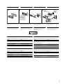
A
How to detach and attach the
front panel
Before installing the unit, detach the front
panel.
A To detach
Before detaching the front panel, be sure to press
(OFF). Press (OPEN), then slide the front panel to
the right side, and pull out the left side.
BTo attach
Place the hole A in the front panel onto the spindle
B on the unit as illustrated, then push the left side in.
Forma de extraer e instalar el
panel frontal
Antes de instalar la unidad, extraiga el panel
frontal.
A Para extraerlo
Antes de extraer el panel frontal, ceriórese de pulsar
(OFF). Después pulse (OPEN) para abrirlo, deslícelo
hacia la derecha, por último, tire de su parte
izquierda.
B Para instalarlo
Coloque el orificio A del panel frontal en el eje B
de la unidad, como se muestra en la ilustración, y
después presione la parte izquierda.
Ta loss/fästa frontpanelen
Ta loss frontpanelen innan du monterar
bilstereon.
A Ta loss frontpanelen
Var noga med att trycka på (OFF) innan
frontpanelen tas loss. Tryck därefter på (OPEN) för
att öppna frontpanelen. Skjut frontpanelen åt höger
och dra dess vänstra del utåt för att ta loss
frontpanelen.
B Fästa frontpanelen
Placera frontpanelen så att hålet A på frontpanelen
träs över axeln B på bilstereon enligt illustrationen.
Tryck därefter frontpanelens vänstra del inåt.
Para retirar e colocar o painel
frontal
Retire o painel frontal antes de iniciar a
instalação do aparelho.
A Para retirar
Antes de retirar o painel frontal, tem de carregar
primeiro em (OFF). A seguir, carregue em (OPEN)
para soltar o painel frontal e empurre-o para a
direita. Depois puxe o lado esquerdo do painel para
fora.
B Para colocar
Coloque o orificio A do painel frontal no eixo B do
aparelho tal como ilustrado, e depois carregue no
lado esquerdo para dentro.
B
c

5
Installation in the dashboard Instalación en el salpicadero Montera på instrumentbrädan Instalação no tablier
1 2 3
Fire wall
Panel cortafuegos
Brandsäker
mellanvägg
Painel corta-fogo
Dashboard
Salpicadero
Instrumentbräda
Tablier
Bend these claws outward
for a tight fit, if necessary.
Si es necesario, doble estas
uñas hacia afuera para que
encaje firmemente.
För att få en tät passning
böj dessa flikar vid behov.
Se necessário, dobre as
unhas para prender melhor.
2
3
4
4
5
7
7
5
5
7
182 m
m
53 m
m
Reset button
When the installation and connections are complete,
be sure to press the reset button with a ballpoint pen,
etc.
Botón de restauración
Cuando finalice la instalación y las conexiones,
cerciórese de pulsar el botón de restauración con un
bolígrafo, etc.
Nollställningsknappen
Kom ihåg att använda en penna eller något annat
spetsigt föremål för att trycka på
nollställningsknappen när anslutningen och
monteringen är klar.
Botão de reinicialização
Quando terminar a instalação e as ligações, não se
esqueça de carregar no botão de reinicialização com a
ponta de uma caneta, esferográfica, etc.
1
1
Note
To prevent malfunction, install only with the supplied
screws 5.
Nota
Para evitar fallos de funcionamiento, realice la
instalación únicamente con los tornillos suministrados
5.
Observera
Använd bara de medföljande skruvarna 5, så
undviker du onödiga fel.
Nota
Para evitar avarias, instale o aparelho apenas com os
parafusos fornecidos 5.
Troubleshooting guide
The following check will assist in the correction of most problems which you may encounter with your unit.
Before going through the check list below, refer to the connection and operating procedures.
Cause
Leads are not matched correctly with the car’s
accessory power connector.
The car doesn’t have an ACC position.
The power aerial does not have a relay box.
Problem
•Memorised stations and correct time are erased.
•The fuse has blown.
•Makes noise when the ignition key is the ON, ACC and
OFF positions.
•No power is being supplied to the unit.
•The power is continuously supplied to the unit.
The power aerial does not extend.
Felsökning
De flesta problem som kan uppstå med enheten kan åtgärdas genom att kontrollera följande. Innan du går igenom
punkterna nedan bör du läsa instruktionerna för anslutning och handhavande.
Orsak
Kablarna är inte kopplade på rätt sätt till bilens
anslutning för tillbehör.
Bilen har inte något ACC-läge.
Motorantennen har ingen relädosa.
Problem
•Minneslagrade stationer och aktuell tid har raderats.
•Säkringen har gått.
•Brus när tändningsnyckeln är i läge ON, ACC och OFF.
•Ingen ström till enheten.
•Kontinuerlig ström till enheten.
Motorantennen åker inte ut.
Guia de detecção de avarias
A verificação seguinte ajuda-o a corrigir a maioria das avarias que podem ocorrer no aparelho. Antes de utilizar a
lista de verificação abaixo, consulte as instruções de funcionamento e de ligação.
Causa
A correspondência entre os fios de ligação e o
conector de alimentação de acessórios não está
correcta.
O carro não tem posição ACC.
A antena eléctrica não tem caixa de relé.
Problema
•As estações memorizadas e a hora correcta são apagadas.
•O fusível rebentou.
•Faz ruído se a chave de ignição estiver nas posições ON,
ACC e OFF.
•O aparelho não está a receber corrente.
•O aparelho está a receber continuamente corrente.
A antena eléctrica não estica.
Guía de solución de problemas
La siguiente lista de comprobaciones le ayudará a solucionar la mayoría de los problemas que puedan surgir con
la unidad. Antes de consultar la lista, compruebe los procedimientos de conexión y funcionamiento.
Causa
Los cables no coinciden correctamente con el
conector de alimentación accesoria del automóvil.
El automóvil no dispone de posición ACC.
La antena motorizada no tiene un dispositivo de
relé.
Problema
•Se han borrado las emisoras memorizadas y la hora
correcta.
•El fusible se ha fundido.
•Se produce ruido cuando la llave de encendido se
encuentra en las posiciones ON, ACC y OFF.
•La unidad no recibe alimentación.
•La unidad recibe alimentación de forma continua.
La antena motorizada no se despliega.

6
Connections
Cautions
•This unit is designed for negative earth 12 V DC
operation only.
•Be careful not to pinch any wires between a
screw and the body of the car or this unit or
between any moving parts such as the seat
railing, etc.
•Connect the power connecting cord 8 to the
unit and speakers before connecting it to the
auxiliary power connector.
•Run all earth wires to a common earth point.
•Connect the yellow cord to a free car circuit
rated higher than the unit’s fuse rating. If you
connect this unit in combination with other
stereo components, the car circuit they are
connected to must be rated higher than the sum
of the individual components’ fuse rating. If
there are no car circuits rated as high as the
unit’s fuse rating, connect the unit directly to the
battery. If no car circuits are available for
connecting this unit, connect the unit to a car
circuit rated higher than the unit’s fuse rating in
such a way that if the unit blows its fuse, no
other circuits will be cut off.
Conexiones
Precauciones
•Esta unidad ha sido diseñada para alimentarse
con 12 V CC, negativo a masa, solamente.
•Tenga cuidado de no atrapar ningún cable entre
algún tornillo y la carrocería del automóvil o
esta unidad o entre las partes móviles, como por
ejemplo los raíles del asiento, etc.
•Conecte el cable de conexión de alimentación 8
a la unidad y los altavoces antes de conectarlo al
conector de alimentación auxiliar.
•Conecte todos los cables de puesta a masa a
un punto común.
•Conecte el cable amarillo a un circuito libre del
automóvil de potencia nominal superior a la del
fusible de la unidad. Si conecta esta unidad en
combinación con otros componentes estéreo, la
potencia nominal del circuito del automóvil a los
que dichos componentes estén conectados debe
ser superior a la suma de la potencia nominal
del fusible de los componentes. Si no existen
circuitos de automóvil de potencia nominal tan
alta como la del fusible de la unidad, conecte
ésta directamente a la batería. Si no hay circuitos
de automóvil disponibles para conectar esta
unidad, conecte la misma a un circuito de
automóvil de potencia nominal superior a la del
fusible de la unidad de forma que no se
desactiven otros circuitos si el fusible de dicha
unidad se funde.
Anslutning
Säkerhetsföreskrifter
•Denna bilstereo är endast avsedd för anslutning
till ett negativt jordat, 12 V bilbatteri.
•Var noga med att inga kablar kläms mellan
någon skruv eller att de blir klämda mellan
rörliga delar som t.ex. bilsätet.
•Anslut strömkabeln 8 till enheten och
högtalarna innan du ansluter den till den yttre
strömanslutningen.
•Dra samtliga jordledningar till en och samma
jordningspunkt.
•Anslut den gula kabeln till en ledig bilkrets med
ett högre amperetal än enhetens. Om du kopplar
både denna enhet och andra stereokomponenter
till en och samma bilkrets, måste den bilkrets de
kopplas till ha en högre ampere än summan av
de enskilda delarnas amperestyrka. Om det inte
finns några bilkretsar med en så hög
amperestyrka som enhetens ska du ansluta
enheten direkt till batteriet. Om inga bilkretsar
finns för anslutning till enheten ska du ansluta
enheten till en bilkrets med ett högre amperetal
än enhetens säkring, så att det är denna som går
i stället för bilens.
Ligações
Cuidado
•Este aparelho foi concebido para funcionar
somente com corrente contínua de 12 V com
negativo à massa.
•Tenha cuidado para que os fios não fiquem
entalados entre os parafusos e a carroçaria do
automóvel ou a caixa do aparelho, nem entre as
peças móveis, por exemplo, as calhas dos
bancos, etc.
•Ligue o cabo de alimentação de corrente 8 ao
aparelho e aos alifalantes antes de o ligar ao
conector de corrente auxiliar.
•Ligue todos os cabos de massa num ponto de
massa comum.
•Ligue o cabo amarelo a um circuito eléctrico
livre do automóvel, cuja potência nominal seja
superior à dos fusíveis do aparelho. Se ligar este
aparelho em série com outros componentes
estéreo, a potência nominal do circuito eléctrico
do automóvel onde os ligar tem de ser superior
à soma da potência nominal dos fusíveis de
todos os componentes individuais. Se não
houver nenhum circuito eléctrico do automóvel
com uma potência nominal tão elevada como a
dos fusíveis do aparelho, ligue-o directamente à
bateria. Se não estiver disponível nenhum
circuito eléctrico do automóvel para ligação
deste aparelho, ligue-o a um circuito eléctrico do
automóvel com uma potência nominal superior
à dos fusíveis do aparelho, de tal modo que, se o
aparelho rebentar os fusíveis respectivos,
nenhum outro circuito seja cortado.
Notes of connection example
Notes on the control leads
• The power aerial control lead (blue) supplies +12 V
DC when you turn on the tuner or when you
activate the ATA (Automatic Tuner Activation), AF
(Alternative Frequency) or the TA (Traffic
Announcement) function.
• A power aerial without a relay box cannot be used
with this unit.
• When your car has a built-in FM/MW/LW aerial in
the rear/side glass, it is necessary to connect the
power aerial control lead (blue) or the accessory
power input lead (red) to the power terminal of the
existing aerial booster. For details, consult your
dealer.
Warning
If you have a power aerial without a relay box,
connecting this unit with the supplied power
connecting cord 8 may damage the aerial.
Memory hold connection
When the yellow power input lead is connected,
power will always be supplied to the memory circuit
even when the ignition switch is turned off.
Notes on speaker connection
• Before connecting the speakers, turn the unit off.
• Use speakers with an impedance of 4 to 8 ohms, and
with adequate power handling capacities.
Otherwise, the speakers may be damaged.
• Do not connect the terminals of the speaker system
to the car chassis, and do not connect the terminals
of the right speaker with those of the left speaker.
• Do not attempt to connect the speakers in parallel.
• Do not connect any active speakers (with built-in
amplifiers) to the speaker terminals of the unit.
Doing so may damage the active speakers. Be sure
to connect passive speakers to these terminals.
Notas de ejemplo de conexiones
Notas sobre cables de control
• El cable de control (azul) de la antena motorizada
suministra + 12 V CC al activar el sintonizador o la
función ATA (activación automática del
sintonizador), AF (frecuencias alternativas) o TA
(anuncios de tráfico).
• Con esta unidad no podrá utilizarse una antena
motorizada sin caja de relés.
• Si el automóvil dispone de antena de FM/MW/LW
incorporada en el cristal trasero/lateral, será
necesario conectar el cable de control de antena
motorizada (azul) o el cable de entrada de
alimentación accesoria (rojo) al terminal de potencia
del amplificador de antena existente. Para más
información, consulte con el proveedor.
Advertencia
Si dispone de una antena motorizada sin dispositivo
de relé, la conexión de esta unidad con el cable de
conexión de alimentación 8 suministrado puede
dañar la antena.
Conexión para protección de la memoria
Si conecta el cable de entrada de alimentación
amarillo, el circuito de la memoria recibirá siempre
alimentación, incluso aunque ponga la llave de
encendido en la posición de apagado.
Notas sobre la conexión de los altavoces
• Antes de conectar los altavoces, desconecte la
alimentación de la unidad.
• Utilice altavoces con una impedancia de 4 a
8 ohmios, y con la potencia máxima admisible
adecuada, ya que de lo contrario podría dañarlos.
• No conecte los terminales del sistema de altavoces al
chasis del automóvil, ni los del altavoz izquierdo a
los del derecho.
• No intente conectar los altavoces en paralelo.
• No conecte altavoces activos (con amplificadores
incorporados) a los terminales de altavoces de la
unidad. Si lo hiciese, podría dañar tales altavoces.
Por lo tanto, cerciórese de conectar altavoces pasivos
a estos terminales.
Att observera angående
anslutningsexemplen
Att observera angående de olika styrkablarna
• Motorantennens styrkabel (blå) leder + 12 V likström
när kanalväljaren slås på eller när
radiomottagningsautomatik ATA, mottagning av
alternativa frekvenser AF eller mottagning av
trafikmeddelanden TA aktiverats.
• En motorantenn utan styrrelädosa kan inte anslutas
till denna bilstereo.
• Om bilen har en FM/MW/LW-antenn som är inbyggd
i sido- eller bakrutan, måste du ansluta
motorantennens styrkabel (blå) eller
tilbehörsströmkabeln (röd) till strömterminalen på
antennförstärkaren. Din återförsäljare kan ge dig
mer information.
Varning
Om du har en motorantenn utan relädosa kan
antennen skadas om du ansluter enheten med den
medföljande strömkabeln 8.
Anslutning för minnesstöd
När du anslutit den gula, ingående strömkabeln
försörjs minneskretsen med ström hela tiden, även när
tändlåset slås ifrån.
Att observera angående högtalarnas anslutning
• Slå av bilstereon innan du ansluter högtalarna.
• Anslut endast högtalare, vars impedans varierar från
4 till 8 ohm och som har tillräcklig
effekthanteringskapacitet för att skydda högtalarna
mot skador.
• Anslut inte något av högtalaruttagen till bilens
chassi. Anslut inte heller uttagen på höger högtalare
till uttagen på vänster högtalare.
• Anslut inte högtalarna parallellt.
• Anslut inte aktiva högtalare (med inbyggda slutsteg)
till bilstereons högtalaruttag, eftersom de kan skada
de aktiva högtalarna. Var noga med att bara ansluta
passiva högtalare till dessa uttag.
Notas sobre o exemplo de ligação
Notas sobre os fios de controlo
• O fio de controlo da antena eléctrica (azul) fornece
+12 V CC quando ligar o sintonizador ou quando
activar as funções ATA (Activação automática do
sintonizador), AF (frequência alternativa) ou TA
(Informações de trânsito).
• Não pode utilizar uma antena eléctrica sem caixa de
relé com este aparelho.
• Se o seu automóvel tiver uma antena de FM/MW/LW
montada no vidro traseiro/lateral, tem de ligar o fio
de controlo da antena eléctrica (azul) ou o fio de
entrada de alimentação para os acessórios
(vermelho) ao terminal de alimentação do
intensificador do sinal da antena existente.
Advertência
Se a antena eléctrica não tiver uma caixa de relé, o
facto de ligar este aparelho com o cabo de
alimentação 8 fornecido, pode provocar danos na
antena.
Ligação para alimentação contínua da memória
Quando o fio amarelo de entrada de alimentação for
ligado, os circuitos de memória ficarão com
alimentação continua, mesmo se a chave de ignição
estiver desligada.
Notas sobre a ligação dos altifalantes
• Antes de ligar os altifalantes, desligue o aparelho.
• Utilize altifalantes com impedância de 4 a 8 ohm, e
com potência máxima admissível adequada. Caso
contrário, os altifalantes poderão sofrer avarias.
• Não ligue os terminais do sistema de altifalantes ao
chassis do automóvel, e não ligue os terminais do
altifalante direito aos terminais do altifalante
esquerdo.
• Não tente ligar os altifalantes em paralelo.
• Não ligue nenhum sistema de altifalantes activos
(com amplificadores incorporados) aos terminais dos
altifalantes do aparelho. Caso o faça, poderá avariar
o sistema de altifalantes activos. Portanto, não se
esqueça de ligar altifalantes passivos a estes
terminais.
Warning when installing in a car
without ACC (accessory) position on
the ignition key switch
Be sure to press (OFF) on the unit for two
seconds to turn off the clock display after
turned off the engine.
When you press (OFF) momentarily, the clock
display does not turn off and this causes battery
wear.
Advertencia sobre la instalación en
un automóvil que no disponga de
posición ACC (accesorios) en el
interruptor de la llave de encendido
Asegúrese de pulsar (OFF) en la unidad
durante dos segundos para desactivar la
indicación del reloj una vez apagado el motor.
Si pulsa (OFF) momentáneamente, la indicación del
reloj no se desactivará y esto causará el desgaste de la
batería.
Aviso sobre a instalação num
automóvel sem posição ACC
(acessórios) na chave de ignição
Verifique se carregou em (OFF) no aparelho
durante dois segundos para desactivar o visor
do relógio depois de ter desligado o motor.
Se carregar ligeiramente em (OFF), não desactiva o
visor do relógio o que provoca o desgaste da bateria.
Var försiktig när du gör
installationen i en bil där
tändningslåset saknar
tillbehörsläge (ACC)
Glöm inte att trycka på (OFF) på enheten
under två sekunder för att stänga av klockans
teckenfönster efter det att du har stängt av
motorn.
Om du bara trycker på (OFF) ett kort ögonblick
slocknar inte klockans teckenfönster vilket kan leda
till att batteriet laddas ur.
Después de realizar la conexión
Una vez realizada la conexión, recoja el cable de
conexión del mando con el resto de los cables de
conexión del equipo de audio mediante el fijador de
cables qa. Como muestra la ilustración, procure dejar
un espacio en el cable de conexión entre el enchufe y
el fijador de cables.
After connecting
After connecting, bundle up the connecting cord of
the rotary commander with other connecting cords of
the audio equipment by attaching the supplied
cramper qa. Be sure to leave some slack in the
connecting cord between the plug and the cramper as
illustrated.
Efter anslutningen
När du är klar fäster du ihop sladden till
vridkontrollen och andra sladdar till
ljudutrustningen med medföljande krampa qa. Se till
så att sladdarna mellan kontakten och
fästanordningen inte blir för hårt spända, se bilden.
Depois de efectuar a ligação
Depois de ter efectuado a ligação, ate o cabo de
ligação do comando aos outros cabos de ligação do
equipamento áudio mediante a utilização da
braçadeira qa fornecida. Deixe alguma folga no cabo
de ligação entre a ficha e a braçadeira, conforme a
ilustração.
qa

7
6
AMP REM
ATT
Max. supply current 0.3 A
Corriente máx. de alimentación de 0,3 A
Maximal strömtillförsel 0,3 A
Corrente máxima de 0,3 A
to the interface cable of a car telephone
al cable de interfaz de un teléfono para
automóvil
till mobiltelefonens gränssnittskabel
Ao cabo de interface de um telefone para
automóvel
to a car’s speaker connector
a un conector de altavoces del automóvil
till bilens högtalaranslutning
ao conector de um altifalante do automóvel
Light blue
Azul celeste
Ljusblå
Azul claro
Blue/white striped
Con raya azul/blanca
Blå/vit-randig
Azul com listras brancas
to a car’s auxiliary power connector
a un conector de alimentación auxiliar del automóvil
till bilens yttre strömanslutning.
a um conector de alimentação auxiliar do automóvel
7
8
switched power supply
suministro conmutado de alimentación
switchad strömförsörjning
alimentação de corrente comutada
earth
toma de tierra
jord
Terra
Yellow
Amarillo
Gul
Amarelo
Blue
Azul
Blå
Azul
Orange/
White
Naranja/
blanco
Orange/vit
Cor de laranja/
branco
Red
Rojo
Röd
Vermelho
Black
Negro
Svart
Preto
continuous power supply
suministro de alimentación continua
kontinuerlig strömförsörjning
alimentação de corrente contínua
power aerial control
control de antena motorizada
styrning av motorantenn
antena eléctrica
switched illumination power supply
fuente de alimentación de iluminación
conmutada
Switchad strömförsörjning till belysning
fonte de alimentação comutada para
iluminação
Speaker, Rear, Right
Altavoz, parte posterior, derecho
Högtalare, bakre, höger
Altifalante, Parte de trás, Direito
Speaker, Rear, Right
Altavoz, parte posterior, derecho
Högtalare, bakre, höger
Altifalante, Parte de trás, Direito
Speaker, Front, Right
Altavoz, parte frontal, derecho
Högtalare, främre, höger
Altifalante, Parte da frente, Direito
Speaker, Front, Right
Altavoz, parte frontal, derecho
Högtalare, främre, höger
Altifalante, Parte da frente, Direito
Speaker, Front, Left
Altavoz, parte frontal, izquierdo
Högtalare, främre, vänster
Altifalante, Parte da frente, Esquerdo
Speaker, Front, Left
Altavoz, parte frontal, izquierdo
Högtalare, främre, vänster
Altifalante, Parte da frente, Esquerdo
Speaker, Rear, Left
Altavoz, parte posterior, izquierdo
Högtalare, bakre, vänster
Altifalante, Parte de trás, Esquerdo
Speaker, Rear, Left
Altavoz, parte posterior, izquierdo
Högtalare, bakre, vänster
Altifalante, Parte de trás, Esquerdo
Purple
Púrpura
Violett
Violeta
Negative polarity positions 2, 4, 6, and 8 have striped cords.
Las posiciones de polaridad negativa 2, 4, 6 y 8 tienen cables con raya.
De negativa polpositionerna 2, 4, 6 och 8 har randiga kablar.
As posi
ç
ões 2, 4, 6 e 8 (polaridade ne
g
ativa) têm cabos às riscas.
Green
Verde
Grön
Verde
White
Blanco
Vit
Branco
Grey
Gris
Grå
Cinzento
+
–
+
–
Positions 1, 2 and 3 do not have pins.
Las posiciones 1, 2 y 3 no disponen de terminales.
Positionerna 1, 2 och 3 saknar stift.
As posições 1, 2 e 3 não têm terminais.
Exemplo de ligações
*
1
Nota referente à ligação da antena
Se a antena do automóvel for uma antena de tipo
ISO (International Organization for
Standardization), utilize o adaptador fornecido 6
para fazer a ligação respectiva.
Ligue primeiro a antena do automóvel ao
adaptador fornecido e depois à tomada de antena
do sistema principal.
*
2
Cabo de terminais RCA (não fornecido)
Anslutningarna enligt exemplet
*
1
Angående antennanslutning
Om motorantennen är av ISO-typ (International
Organization for Standardization), använder du
medföljande adapter 6 för att ansluta den.
Anslut först motorantennen till medföljande
adapter och därefter till antennuttaget på
huvudenheten.
*
2
Kabel med RCA-kontakter (medföljer inte)
Ejemplo de conexiones
*
1
Nota sobre la conexión de la antena
Si la antena del automóvil es del tipo ISO
(International Organization for Standardization),
emplee el adaptador suministrado 6 para
conectarla.
En primer lugar, conecte la antena del automóvil al
adaptador suministrado y, a continuación, a la
toma de antena de la unidad principal.
*
2
Cable con clavijas RCA (no suministrado)
Connection example
*
1
Note for the aerial connecting
If your car aerial is an ISO (International
Organisation for Standardisation) type, use the
supplied adaptor 6 to connect it.
First connect the car aerial to the supplied adaptor,
then connect it to the aerial jack of the master unit.
*
2
RCA pin cord (not supplied)
Source selector
(not supplied)
Selector de fuente (no
suministrado)
Väljare för ljudkälla
(medföljer inte)
Selector de fonte (não
fornecido)
XA-C30
BUS AUDIO IN
AUDIO OUT FRONT
BUS
CONTROL IN
AUDIO OUT REAR
REMOTE IN
Supplied to XA-C30
Suministrado con el XA-C30
Medföljer XA-C30
Fornecido para o XA-C30
Supplied to the CD/MD changer
Suministrado con el cambiador de CD/MD
Medföljer CD/MD-växlaren
Fornecido para o permutador de CD/MD
from car aerial*
1
de la antena del automóvil*
1
från bilantenn*
1
da antena do automóvel*
1
WARNING
Auxiliary power connectors may vary depending on
the car. Be sure to check the power connection
diagram. Improper connections may damage your car.
If the supplied power connecting cord can not be used
with your car, consult your nearest Sony dealer.
ADVERTENCIA
Los conectores de alimentación auxiliar pueden variar
en función del automóvil. Asegúrese de consultar el
diagrama de conexión de alimentación. Las conexiones
incorrectas pueden dañar el automóvil. Si no es
posible utilizar con el automóvil el cable de conexión
de alimentación suministrado, póngase en contacto
con el proveedor Sony más próximo.
VARNING
Typen av yttre strömanslutning varierar från bil till bil.
Kontrollera strömanslutningsschemat som medföljer
enheten så att du ansluter på rätt sätt. Felaktig
anslutning kan skada bilen. Kontakta närmaste Sony-
återförsäljare om den medföljande strömkabeln inte
passar till din bil.
ADVERTÊNCIA
Os conectores de corrente auxiliar podem variar de
carro para carro. Não se esqueça de verificar o
diagrama de ligação de corrente fornecido com o
aparelho. As ligações mal executadas podem
danificar o seu carro. Se não puder utilizar o cabo de
alimentação fornecido no seu carro, contacte o
agente Sony da sua zona.
Rotary commander RM-X4S
Mando rotativo RM-X4S
Vridkontroll RM-X4S
Comando rotativo RM-X4S
Fuse (10 A)
Fusible (10 A)
Säkring (10 A)
Fusivel (10 A)
8
*
2
Insert with the cord upwards.
Insertar con el cable hacia arriba.
Sätt in med kabeln vänd uppåt.
Inserir com o fio virado para cima.
5
6
7
8
1
2
3
4
+
–
+
–
4
5
6
(XR-C7500R/XR-C7500RX: AEP, UK)

8
(XR-C7500RX: E)

9
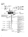
Power connection diagram
Auxiliary power connector may vary depending on
the car. Check your car’s auxiliary power connector
diagram to make sure the connections match
correctly. There are three basic types (illustrated
below). You may need to switch the positions of the
red and yellow leads in the car stereo’s power
connecting cord.
After matching the connections and switched power
supply leads correctly, connect the unit to the car’s
power supply. If you have any questions and
problems connecting your unit that are not covered
in this manual, please consult the car dealer.
Diagrama de conexión de
alimentación
El conector de alimentación auxiliar puede variar en
función del automóvil. Compruebe el diagrama del
conector de alimentación auxiliar del automóvil para
asegurarse de que las conexiones coinciden
correctamente. Existen tres tipos básicos, ilustrados a
continuación. Es posible que sea necesario cambiar
las posiciones de los cables rojo y amarillo del cable
de conexión de alimentación del sistema estéreo del
automóvil.
Después de hacer coincidir correctamente las
conexiones y los cables de alimentación conmutada,
conecte la unidad al suministro de alimentación del
automóvil. Si desea realizar alguna consulta o
solucionar algún problema referentes a la conexión
de la unidad que no aparezcan en este manual,
consulte con el concesionario automovilístico.
Strömanslutningsschema
Typen av yttre strömanslutning varierar från bil till
bil. Kontrollera schemat till strömanslutningen så att
du ansluter på rätt sätt. Det finns tre grundläggande
anslutningstyper (visas nedan). Du kan behöva skifta
plats på bilstereons röda och gula
strömförsörjningskablar.
Koppla kablarna för kontinuerlig respektive switchad
strömförsörjning på rätt sätt och anslut sedan
enheten till bilens strömanslutning. Om du får
problem eller har frågor som inte besvaras i den här
bruksanvisningen kan du kontakta bilåterförsäljaren.
Diagrama de ligação de corrente
O conector auxiliar de corrente pode variar de carro
para carro. Verifique o diagrama do conector auxiliar
de corrente para se certificar de que as ligações estão
bem feitas. Existem três tipos de conectores
(ilustrados abaixo).
Depois de fazer a correspondência entre as ligações e
os terminais de alimentação de corrente comutada,
ligue o aparelho à fonte de alimentação do carro. Se
tiver alguma dúvida ou problema relacionado com o
aparelho que não esteja incluído neste manual,
consulte o concessionário.
Auxiliary power connector
Conector de alimentación auxiliar
Yttre strömanslutning
Conector de corrente auxiliar
4
7
Yellow
Amarillo
Gul
Amarelo
Red
Rojo
Röd
Vermelho
continuous power supply
suministro de alimentación continua
kontinuerlig strömförsörjning
alimentação de corrente contínua
switched power supply
suministro conmutado de alimentación
switchad strömförsörjning
alimentação de corrente comutada
Red
Rojo
Röd
Vermelho
the car without ACC position
automóvil sin posición ACC
bil utan ACC-läge
o carro sem posição ACC
Red
Rojo
Röd
Vermelho
Red
Rojo
Röd
Vermelho
Red
Rojo
Röd
Vermelho
Yellow
Amarillo
Gul
Amarelo
Yellow
Amarillo
Gul
Amarelo
Yellow
Amarillo
Gul
Amarelo
Yellow
Amarillo
Gul
Amarelo
4
7
Yellow
Amarillo
Gul
Amarelo
Red
Rojo
Röd
Vermelho
switched power supply
suministro conmutado de alimentación
switchad strömförsörjning
alimentação de corrente comutada
continuous power supply
suministro de alimentación continua
kontinuerlig strömförsörjning
alimentação de corrente contínua
Red
Rojo
Röd
Vermelho
Red
Rojo
Röd
Vermelho
Yellow
Amarillo
Gul
Amarelo
Yellow
Amarillo
Gul
Amarelo
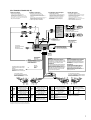
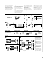
Connection diagram
AC
Equipment used in illustrations
(not supplied)
Equipo utilizado en las ilustraciones
(no suministrado)
Utrustning som visas i illustrationer
(medföljer inte)
Equipamento utilizado nas ilustrações
(não fornecido)
Notes
• For connecting two or more CD/MD
changers, the source selector XA-C30
(optional) is necessary.
• Be sure to connect the earth cord before
connecting the amplifier.
• If you connect an optional power amplifier
and do not use the built-in amplifier, the
beep sound will be deactivated.
Notas
• Si desea conectar dos o más cambiadores,
necesitará el selector de fuente XA-C30
(opcional).
• Asegúrese de conectar primero el cable de
puesta a masa antes de realizar la conexión
al amplificador.
• Si conecta un amplificador de potencia
opcional y no utiliza el incorporado, los
pitidos se desactivarán.
Obsevera
• För anslutning av två eller flera växlare
krävs väljarna XA-C30 (tillval).
• Var noga med att först ansluta jorden,
innan du ansluter förstärkaren.
• Om du väljer att använda en annan
förstärkare i stället för den inbyggda,
kommer ljudsignalen att avaktiveras.
Notas
• Para ligar um ou mais permutadores, é
necessário o selector de fonte XA-C30
(opcional).
• Antes de fazer a ligação ao amplificador
tem de ligar primeiro o cabo de ligação à
massa.
• Se ligar um amplificador de potência
opcional e não utilizar o amplificador
integrado, desactiva o sinal sonoro.
Diagrama de conexiones Kopplingsschema Diagrama de ligações
BUS
AUDIO IN
AUDIO OUT
FRONT
Source selector*
Selector de fuente*
Väljare för ljudkälla*
Selector de fonte*
BUS
CONTROL IN
AUDIO OUT
REAR
Front speaker
Altavoz delantero
Främre högtalare
Altifalante dianteiro
Rear speaker
Altavoz trasero
Bakre högtalare
Altifalante traseiro
Power amplifier
Amplificador de potencia
Effektförstärkare
Amplificador de potência
CD/MD changer
Cambiador de CD/MD
CD/MD-skivväxlare
Permutador CD/MD
SUB OUT
BUS CONTROL IN
BUS AUDIO IN
BUS AUDIO IN
BUS CONTROL IN
B
DAB tuner unit*
Sintonizador DAB*
DAB-tunerenhet*
Sintonizador DAB*
XT-100DAB
* not supplied
no suministrado
medföljer inte
não fornecido
* not supplied
no suministrado
medföljer inte
não fornecido

10
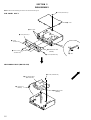
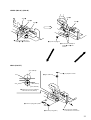
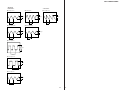
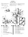
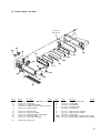
SECTION 3
DISASSEMBLY
SUB PANEL ASS’Y
MECHANISM DECK (MG-25G-136)
Note: Follow the disassembly procedure in the numerical order given.
4 two claws
1 screw (PTT2.6 × 5)
2 cover
3 screw
(PTT2.6 × 6)
6 sub panel ass’y
3 four screws
(PTT2.6 × 6)
3 screw (PTT2.6 × 6)
5 flexible flat cable
(CN580)
4 claw
3 screw (PTT2.6 × 6)
4 mechanism deck
(MG-25G-136)
1 flexible boar
d
(CN250)
2 connector
(CN201)

11
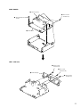
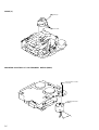
MAIN BOARD
HEAT SINK (2P)
2 three ground point
screws
3 rubber cap (25)
1 three screws
(PTT2.6 × 8)
4 main board
1 three screws
(PTT2.6 × 8)
2 two screws
(PTT2.6 × 12)
1 three screws
(PTT2.6 × 8)
3 heat sink (2P)

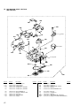
12
HOUSING
ARM (SUCTION)
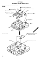
Note: Follow the assembly procedure in the numerical order given.
SECTION 4
ASSEMBLY OF MECHANISM DECK
A part
C part
B part
D part
8 Hold the hanger by
bending the claw.
6 Fit projection on D part.
4 Fit claw on B part.
3 Put the housing
under A part.
5 Fit projection on C part.
1 Install the catch to the hanger.
2 Install the hanger onto
two claws of the housing.
7 Hold the hanger by bending the claw.
hanger
housing
2 Move the arm (suction) in the arrow
direction and fit on projection.
1 Fit the arm (suction) on the shaft.
projection

13
LEVER (LDG-A) / (LDG-B)
GEAR (LDG-FT)
shaft A
shaft B
shaft C
1 Fit the lever (LDG-A) on
shafts A – C and install it.
shaft A
shaft B
2 Fit the lever (LDG-B) on
shafts A and B and
install it.
3 type-E stop ring 2.0
gear (LDG-D)
5 gear (LDG-FT)
6 polyethylene washer
2 tension spring (LD-2)
2 tension spring (LD-1)
gear (LDG-FB)
lever (LDG-A)
hole
hole
4 Align hole in the gear (LDG-D)
with hole the lever (LDG-A).
3 Move the lever (LDG-B)
in the direction of the arrow .
1

14
GUIDE (C)
MOUNTING POSITION OF CAPSTAN/REEL MOTOR (M901)
2 guide (C)
1 three claws
two precision screws
(P2 × 2)
capstan/reel motor
(M901)
30˚

15
SECTION 5
MECHANICAL ADJUSTMENTS
• Tape Tension Measurement
1. Clean the following parts with a denatured-alcohol-moistened
swab:
playback head pinch roller
rubber belt capstan
idler
2. Demagnetize the playback head with a head demagnetizer.
3. Do not use a magnetized screwdriver for the adjustments.
4. After the adjustments, apply suitable locking compound to the
parts adjusted.
5. The adjustments should be performed with the power supply
voltage unless otherwise noted.
• Torque Measurement
Mode Torque Meter Meter Reading
2.95 – 6.37 mN•m
Forward CQ-102C (30 – 65 g•cm)
(0.42 – 0.90 oz•inch)
Forward
0.05 – 0.44 mN•m
CQ-102C (0.5 – 4.5g•cm)
Back Tension
(0.01 – 0.06 oz•inch)
2.95 – 6.37 mN•m
Reverse CQ-102RC (30 – 65 g•cm)
(0.42 – 0.90 oz•inch)
Reverse
0.05 – 0.44 mN•m
CQ-102RC (0.5 – 4.5g•cm)
Back Tension
(0.01 – 0.06 oz•inch)
5.89 – 19.61 mN•m
FF, REW CQ-201B (60 – 200 g•cm)
(0.83 – 2.78 oz•inch)
Mode Tension Meter Meter Reading
more than 8.83 mN•m
Forward CQ-403A (more than 90 g)
(more than 3.18 oz)
more than 8.83 mN•m
Reverse CQ-403R (more than 90 g)
(more than 3.18 oz)
SECTION 6
ELECTRICAL ADJUSTMENTS
TEST MODE
This set has the test mode function.
<Set the Test Mode>
1. Turn ON the regulated power supply. (The clock is displayed)
Note: Press the [OFF] button, if the clock is not displayed.
2. Press the preset [4] button.
3. Press the preset [5] button.
4. Press the preset [1] button for more than two seconds.
5. Then the display indicates all lights, the test mode is set.
<Release the Test mode>
1. Press the [OFF] button.

16
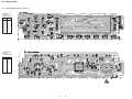
Adjustment Location:
– SET UPPER VIEW –
– SET BOTTOM VIEW –
Tape Speed Adjustment
Setting:
Procedure:
1. Put the set into the FWD PB mode.
2. Adjust adjustment resistor for inside capstan motor so that the
reading on the speed checker or frequency counter becomes in
specification.
Specification: Constant speed
Dolby Level Adjustment
Setting:
[MENU] button : ON (light up SET UP and
PLAY MODE)
Preset [DISC +]
t [+ ] (t) buttons : NR off
[DSO] (BAS, TRE) button : off
[SOUND] (BAL) button : Center
[SOUND] (FAD (Front)) button : Center
[SOUND] (FAD (Rear)) button : Center
VOLUME CONTROL dial : Maximum
Procedure:
1. Put the set into the FWD PB mode.
2. Adjust RV230 (L-CH) and RV240 (R-CH) so that the level
meter reading is –6±0.5 dB (0.37 to 0.41 V).
set
+
–
test tape
P-4-D400
(400Hz, 0 dB) level mete
r
MAIN board
TP (DOLBY-L)/
TP (DOLBY-R)
0 dB=0.775 V
TAPE DECK SECTION
Speed checker Frequency counter
–1.5 to +2.5% 2,955 to 3,075 Hz
set
+–
test tape
WS-48A
(3 kHz, 0 dB)
LINE OUT REAR jack (CN13)
10 kΩ
speed checker
or
frequency counte
r
> M
TUX1
Tape Speed Adjustment
RV240
Dolby Level Adjustment (R-CH)
RV230
Dolby Level Adjustment (L-CH)
TP (DOLBY-R)
TP (DOLBY-L)
Dolby Level
Adjustment
TP
(GND)
TUNER SECTION
Tuner section adjustments are done automatically in this set.

1717
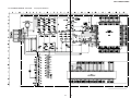
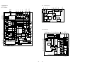
XR-C7500R/C7500RX
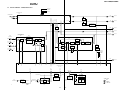
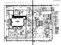
SECTION 7
DIAGRAMS
7-1. BLOCK DIAGRAM – TUNER/TAPE Section –
1
2
FM-ANT
AM-ANT
53
VSM
AMSIN
32
TUNATT
14
S-METER
10
MPX
8
AM-DET
9
RDSDET
05
MUTING
Q22
BUFFER
Q50
MUTING
Q21
D20
FM/AM TUNER UNIT
TUX1
SYSTEM CONTROLLER
IC600 (1/4)
17
EEPROM SDL
J1
(FM/AM ANTENNA)
5
VCC
TUNER VCC
16
VDD
TUNER +5V
11
BU 5V
10
52
MPTH
75
DAVN
RDS DECODER
IC50
INTERFACE
REGISTER
IIC BUS
SLAVE
TRANSCEIVER
OSCILLATOR
& CLOCK
X50
4.332MHz
4
8
5
OSCI
OSCO
SDA
SCL
DAVN
57 kHz
BAND-PASS
FILTER
CLOCKED
COMPARATOR
RDS/RDBS
DEMODULATOR
& DECODER
SIGNAL
QUALITY
DECODER
16
18
19
MPX
CIN
4
5
SC
OUT
MULTI
PATH
DETECTOR
20
2
LVIN
MPTH
50
QUALITY
56
NS MASK
BAND-PASS
FILTER
IC90
MUTING CONTROL
SWITCH
Q20
NOISE DET
DISCHARGE
SWITCH
Q601
DATA
CLOCK
DATA,CLOCK
(Page 18)
MPX
(Page 18)
A
AM
(Page 18)
B
LEVEL
(Page 18)
F
BACKUP +5V
T. ROM-SDA
18
EEPROM SCL
T. ROM-SCL
SDA
SCL
4
FM AGC
51
FM AGC
BUFFER
Q11
DATA
12 13
AM-IF
19
CLOCK
10
E
AM-IF
(Page 18)
C
9
RV230
DOLBY LEVEL (L)
TAPE EQUALIZER AMP,
DOLBY NR AMP, AMS
IC250
34
32
R-CH
PBF
IN1
FWD
L-CH
HP901
(PLAYBACK)
FWD
R-CH
REV
L-CH
REV
R-CH
PBR
IN1
R-CH
R-CH
R-CH
R-CH
R-CH
R-CH
EQ AMP
29 27
MUTE
DOLBY
NR AMP
PB
OUT1
TAPE
IN1
AMS
DET
+
19
DRSW
18
TAPESW
20
INSW
DOLBY
MSSW
24
LINE
OUT1
14
MS
OUT
TAPE L
(Page 18)
D
• SIGNAL PATH
: MW/LW
: FM
: TAPE PLAY
REGULATOR
CONTROL SWITCH
Q202
CAPSTAN/REEL
MOTOR DRIVE
Q204
TAPEON
CM-ON
VCC
REEL SENSOR B+
BATT B+
BATT B+
Q205
IN1
IN2
OUT1
OUT2
LOADING/TAPE OPERATION
MOTOR DRIVE
IC201
61
M
M
M901
(CAPSTAN/REEL)
9
7
MOTOR
DRIVE
3
4
1
LM-EJ
59
LM-LOD
60
REGULATOR
Q203
62
LOADING/TAPE
OPERATION
TAPE OPERATION
SWITCH
BUFFER
TAKE-UP
REEL
SENSOR
SUPPLY
REEL
SENSOR
REEL SENSOR BOARD
REEL
5865 – 68
POS0 – POS3
TAPE
DETECT
EJECT/FF/REW/
REV/FWD MODE DETECT
11
2
AMSON
3
TAPE ATT
9
DOLBY
120
MTLOUT
57
F/R
7
16
17

1818
XR-C7500R/C7500RX
05
H
(Page 20)
AMPON
SYSTEM CONTROLLER
IC600 (2/4)
CN13 (2/2)
AUDIO
OUT FRONT
AUDIO
OUT REAR
MUTING
Q311
MUTING
Q411
MUTING
Q331
MUTING
Q431
FL+
1
12
14
5
3
OUT2+
OUT2–
21
23
OUT4+
OUT4–
IN2
IN4
11
9
7
OUT1+
OUT1–
IN1
15
17
19
OUT3+
OUT3–
IN3
22
MUTE
16
105
15
AC GND
4
STBY
CN700 (1/2)
(POWER CONNECTOR)
POWER AMP
IC700
FL–
9
FR+
4
FR–
12
RL+
2
RL–
10
RR+
3
RR–
11
TEST
15
TEL-ATT
13
R-CH
R-CH
41
40
XTLI38
X100
16.9344MHz
XTLO38
LOW-PASS
FILTER
IC301
CENTER VOLTAGE
GENERATOR
(FOR BIAS)
IC41
DIGITAL SIGNAL PROCESSOR,
DIGITAL FILTER,
D/A CONVERTER
IC100
27
29
AOUTL1
AOUTR1
54
52
AOUTR3
AOUTL3
60
61
35
LIN
46
RIN
REDY
TRDT
63
RVDT
59
SCK
62
57
TRDT
XLAT
REDY
DSPRST
SCK
RVDT
TRDT
XLAT
REDY
DSPRST
DSPDATA
DSPCKO
SCK
RVDT
L
R
L
R
L
R
R-CH
R-CH
CN13 (1/2)
BUS
AUDIO IN
MONO FADER MIXER
SUBWOOFER+
PHASE CONTROL
MONO
FADER
34
ACINLF
33
35
ACINLR
SWINR
29
30
OUTLF
OUTLR
OUTSWR
ELECTRICAL VOLUME
IC10 (2/2)
XLAT
36
78
DSPREADY
35
26
DSPSO
27
DSPCKO
25
DSPSI
DSPLAT
DSPRST
R-CH
R-CH
FL-OUT
RL-OUT
FR-OUT
RR-OUT
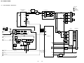
• SIGNAL PATH
: TAPE PLAY
: FM
: MW/LW
: BUS AUDIO IN
XRST
AUDIO
+9V
R-CH
OUTPUT
SELECTOR
25
LINE
DRIVER
IC300
MUTING
CONTROL SWITCH
Q700, 701
I
(Page 20)
BUIN
LEVEL SHIFT
Q600
38
18
11
20
1
SEL
AM
FD1L–
12
AMIF
13
MPX
R-CH
SOFT
MUTE
TONE
CONTROL
LOUDNESS/
VOLUME
INPUT SELECT, FM MPX
IC10 (1/2)
PILOT
CANCELATION
DIGITAL
CONTROL
L.P.F.
PLL
QUAL
IIC BUS
SDA
SCL
DATA
CLOCK
QUALITY
PILOT
DET
+STEREO ADJUST
+STEREO BLEND
L.P.F. S & H HIGH-CUT
D/A
CONVERTER
MULTIPATH
DETECTOR
DEMODULATOR
21 18
MPOUT
16
MPIN
15
LEVEL
14
INPUT
MULTIPLEXER
LOUDNESSMUTE
AM/FM
NOISE
BLANKER
TO
OUTPUT
SELECTOR
ACOUTL
SM
B
(Page 17)
AM
D
(Page 17)
TAPE L
C
(Page 17)
AM-IF
A
(Page 17)
MPX
E
(Page 17)
DATA, CLOCK
F
(Page 17)
LEVEL
G
(Page 19)
DSPDATA, DSPCKO
31
VOLATT
70
I2C-SDA
71
I2C-SCL
DATA
CLOCK
84
TESTIN
96
TELATT
55
AMPON
5
ATT
4
MUTING
Q312
MUTING
Q412
MUTING
Q332
MUTING
Q432
R-CH
R-CH
AMPATT
BEEP
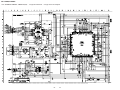
7-2. BLOCK DIAGRAM – MAIN Section –

1919
XR-C7500R/C7500RX
LED910 – 915
(LCD BACK LIGHT)
(XR-C7500RX)
(XR-C7500R) (XR-C7500R)
05
80
REIN1
KEYACK
GREEN
79
62
TX
13
85
96
OSC
KEYIN1
REIN0
116 115
KEYIN0
X1
X0
X1A
X0A
RCIN0
RCIN1
46
47
48 72
93
92
73
74
KEY ACTIVE
SWITCH
Q406, 407
OSC
D580
D520
AMBER
AD-ON
117
NOSE-SW
RX
G
(Page 18)
J
(Page 20)
DSPDATA,DSPCKO
LSW801,901–917,
S901 – 904
S600
(NOSE DETECT)
ROTARY
ENCODER
RE901
B/U +5V
CN901
FRONT PANEL SIDE
CNP801
(XR-C7500R)
CN801
(XR-C7500RX)
MAIN BODY SIDE
BATT B+
8 1
LED
DRIVE
Q902
X601
3.68MHz
X600
32.768kHz
XTAL
EXTAL
85
86
X800
18.432MHz
C953, R957
SYSTEM CONTROLLER
IC600 (3/4)
LIQUID CRYSTAL DISPLAY
DRIVE CONTROLLER
IC800 (1/2)
LIQUID CRYSTAL DISPLAY DRIVER
IC901
1 – 74
SEG1 – SEG74
83 – 76
COM1 – COM8
LIQUID CRYSTAL DISPLAY
LCD901
VOLUME/BALANCE/
FADER CONTROL
RE901
J520
REMOTE IN
DOORIND
118
LED DRIVE
Q580
LCD-DATA
100
LCD-CLK
99
LCD-CE
98
TX/LCD-DATA
60
RX
12
LCD-SCK
64 66
LCD-CE1
SP-SCK
61
SP-SI
TRDT
SCK
63
SP-LAT
BOOT
33 57
4
106
SA LAT
BOOT
LED801
(TAPE WINDOW),
LSW801
84
DIMMER
86
LED DRIVE
Q903
Z
(XR-C7500RX)
LED
DRIVE
Q901
LCD B+
LSW901 – 908,
LSW910 – 917
RX
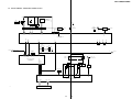
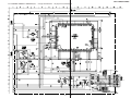
7-3. BLOCK DIAGRAM – DISPLAY/KEY CONTROL Section –

2020
XR-C7500R/C7500RX
B/U +5V
RESET SIGNAL
GENERATOR
IC560
REMOTE CONTROL
RECEIVER
IC951
SIRCS
BUFFER
Q503
BATTERY
DETECT
Q500
S500
6
8
4
CLK
CLK IN
DATA OUT
DATA
2
RST
RESET
SWITCH
BUS ON
SWITCH
13
11
1
BUS ON
OUT
BUS
ON IN
12
9
DATA IN
SONY BUS INTERFACE
IC500
SYSTEM CONTROLLER
IC600 (4/4)
BUS ON/OFF SWITCH
Q502
BATT
BATT B+
BUIN
BUS ON
DATA
CLK
RESET
7
6
5
4
2
SIRCS
3
CN500
BUS CONTROL IN
(FOR SONY BUS)
05
RST
3
BATT
BATTERY
SWITCH
10
BU IN
77
14
19
UNICKO
17
UNISI
18
UNISO
86
HSTX
6
24
SIRCS
85
RAMBU
90
TH501
D507
D500
B+ SWITCH
Q81, 82
FLASH ON
83
82
RESET
SYSRST
BU-IN
BUS-ON
PWON
113
TUNON
LEVEL SHIFT
Q501
LIQUID CRYSTAL DISPLAY
DRIVE CONTROLLER
IC800 (2/2)
UNISI
97
UNISO
50
LINK OFF
UNICKI
52ILL-ON
BU-IN
BUS-ON
RESET
101
38
49
NMI (H)
82
81
98
RESET
LEVEL SHIFT
IC801
AMP-R
AMPON
ANT-R
B+
5
6
16
ACC
7
D501
RAM RESET
IC570
B/U +5V
D591
D592
ACCESSORY
CHECK
Q660
ILL
14
ILLUMINATION
LINE DETECT
Q640
D703
D705
ACCIN
81
ILLIN
95
TH700
TH701
ANTENNA
REMOTE SWITCH
Q710, 711
AMP
REMOTE SWITCH
Q720, 721
H
(Page 18)
I
(Page 18)
AUDIO +9V
B/U +5V
DSP CIRCUIT
B+
DIGITAL +3.3V
ANALOG +3.3V
TUNER VCC
TUNER CIRCUIT
B+
BATT B+
POWER AMP
(IC700) B+
LCD B+
LCD DRIVER
(IC901) B+
TUNER +5V
TUNER CIRCUIT/
RDS DECODER
(IC50) B+
+10V REGULATOR
Q582
D801
RX
J
(Page 19)
BATTERY OFF
MUTE DRIVER
Q704, 705
POWER ON/OFF
SWITCH
Q583
REGULATOR
CONTROL SWITCH
Q581
CN700 (2/2)
(POWER CONNECTOR)
+5V REGULATOR
Q70
+9V REGULATOR
IC530
+3.3V REGULATOR
IC130, Q130
+3.3V REGULATOR
IC170
+5V REGULATOR
IC550
LED901 – 904
(ILLUMINATION)
LSW909
DSO
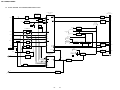
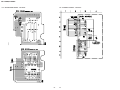
7-4. BLOCK DIAGRAM – BUS CONTROL/POWER SUPPLY Section –
A página está carregando...
A página está carregando...
A página está carregando...
A página está carregando...
A página está carregando...
A página está carregando...
A página está carregando...
A página está carregando...
A página está carregando...
A página está carregando...
A página está carregando...
A página está carregando...
A página está carregando...
A página está carregando...
A página está carregando...
A página está carregando...
A página está carregando...
A página está carregando...
A página está carregando...
A página está carregando...
A página está carregando...
A página está carregando...
A página está carregando...
A página está carregando...
A página está carregando...
A página está carregando...
A página está carregando...
A página está carregando...
A página está carregando...
A página está carregando...
A página está carregando...
A página está carregando...
-
 1
1
-
 2
2
-
 3
3
-
 4
4
-
 5
5
-
 6
6
-
 7
7
-
 8
8
-
 9
9
-
 10
10
-
 11
11
-
 12
12
-
 13
13
-
 14
14
-
 15
15
-
 16
16
-
 17
17
-
 18
18
-
 19
19
-
 20
20
-
 21
21
-
 22
22
-
 23
23
-
 24
24
-
 25
25
-
 26
26
-
 27
27
-
 28
28
-
 29
29
-
 30
30
-
 31
31
-
 32
32
-
 33
33
-
 34
34
-
 35
35
-
 36
36
-
 37
37
-
 38
38
-
 39
39
-
 40
40
-
 41
41
-
 42
42
-
 43
43
-
 44
44
-
 45
45
-
 46
46
-
 47
47
-
 48
48
-
 49
49
-
 50
50
-
 51
51
-
 52
52


Sony Ericsson XR-C7500RX Manual do usuário
- Categoria
- Toca-fitas
- Tipo
- Manual do usuário
Outros documentos
-
Sony XR-C7500R Manual do proprietário
-
-
-
-
-
-
-
-
CAME RBE-RE Guia de instalação
-
Realistic DX-200 Manual do usuário