
28A
24A
bi-amped, active
loudspeaker systems

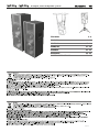
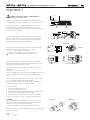
28A - 24A bi-amped, active loudspeaker systems
ITALIANO 3 - 8
ENGLISH 9 - 14
DEUTSCH 15 - 20
FRANÇAIS 21 - 26
ESPAÑOL 27 - 32
APPENDIX 33 - 42
SAFETY INSTRUCTIONS 43 - 45
July 2009

28A - 24A bi-amped, active loudspeaker systems
__________________________________________
__________________________________________
__________________________________________
__________________________________________
__________________________________________
__________________________________________
__________________________________________
__________________________________________
__________________________________________
__________________________________________
__________________________________________
INDICE
Introduzione
Descrizione
Pannello controlli e connessioni
Importante !!!
Appendice:
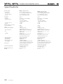
Dati tecnici
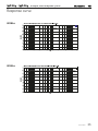
Curva di risposta
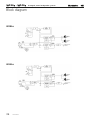
Schema a blocchi
Connettori
Esempi di collegamento
Parti di ricambio
4
4
5
6 - 8
33 - 43
34
35
36
37
38 - 40
41 - 42
ITALIANO
ITALIANO
3
Il lampo con la freccia inserito in un triangolo equilatero avvisa l'utilizzatore della presenza
di tensione pericolosa, senza isolamento, all'interno dell'apparecchio che potrebbe essere
sufcientemente alta da generare il rischio di scossa elettrica.
Il punto esclamativo inserito in un triangolo equilatero avvisa l'utilizzatore della presenza di
importanti istruzioni per l'utilizzo e per la manutenzione.
CONTENUTO DELL’IMBALLO
Sistema attivo biamplicato
Connettore PowerCon
®
Manuale istruzioni
Certicato di garanzia
Dichiarazione di conformità CE
IMPORTANTE ! Norme di sicurezza
ATTENZIONE
Nell'interesse della propria e della altrui sicurezza, e per non invalidare
la garanzia, si raccomanda una attenta lettura di questa sezione prima di
utilizzare il prodotto.
- Questo apparecchio è stato progettato e costruito per venire utilizzato come sistema
di altoparlanti con amplicatore nel contesto tipico di un sistema di amplicazione
sonora e/o di un sistema di registrazione sonora. L'utilizzo per scopi diversi da questi
non è contemplato dal costruttore, ed avviene pertanto sotto la diretta responsabilità
dell'utilizzatore/installatore.
- Questo apparecchio è conforme alla Classe di isolamento I (è necessario il
collegamento alla terra di protezione).
PER EVITARE IL RISCHIO DI INCENDIO E/O DI FOLGORAZIONE:
• Non esporre il prodotto alla pioggia, non utilizzarlo in presenza di elevata umidità
o vicino all'acqua. Non lasciare penetrare all'interno dell'apparecchio alcun liquido,
né alcun oggetto solido. In caso ciò avvenga, scollegare immediatamente
l'apparecchio dalla rete elettrica e rivolgersi ad un servizio di assistenza qualicato
prima di adoperarlo nuovamente. Non appoggiare candele accese od altre sorgenti
di amma nuda sopra l'apparecchio.
• Prima di collegare l'apparecchio alla rete elettrica assicurarsi che la tensione
corrisponda a quella indicata sull'apparecchio stesso.
• Collegare questo apparecchio esclusivamente ad una presa di corrente dotata
di contatto di terra, rispondente alle norme di sicurezza vigenti, tramite il cavo di
alimentazione in dotazione. Nel caso in cui il cavo necessiti di sostituzione, utilizzare
esclusivamente un cavo di identiche caratteristiche.
• L'apparecchio è collegato alla rete anche quando l'interruttore di rete è in posizione
'0' (spento) e la spia luminosa è spenta. All'interno sono presenti potenziali elettrici
pericolosi. Prima di qualunque intervento di manutenzione, scollegare il cavo di
alimentazione dalla presa di rete.
• Non appoggiare alcun oggetto sul cavo di alimentazione. Non posarlo dove possa
costituire intralcio e causare inciampo. Non schiacciarlo e non calpestarlo.
• Installare questo apparecchio prevedendo ampio spazio circostante per un'abbon-
dante circolazione d'aria, necessaria al raffreddamento. Non ostruire le aperture o
le prese d'aria presenti sull'apparecchio. Lasciare spazio sufciente per accedere alla
presa di alimentazione elettrica e al connettore di rete sul pannello posteriore.
• In caso di sostituzione del fusibile esterno, utilizzare esclusivamente un fusibile di
caratteristiche identiche, come riportato sull'apparecchio.
• Prima di effettuare qualsiasi operazione di collegamento, assicurarsi che l'interruttore
di accensione dell'apparecchio sia in posizione '0'.
• Prima di effettuare qualsiasi spostamento del prodotto già installato o in funzione,
rimuovere tutti i cavi di collegamento.
• Per scollegare l'apparecchio dalla rete elettrica, non tirare mai lungo il cavo, ma
afferrarlo sempre per il connettore.
ATTENZIONE!
Questo apparecchio non contiene parti interne destinate all'intervento
diretto da parte dell'utilizzatore. Per evitare il rischio di incendio e/o
folgorazione, non smontarlo e non rimuovere il pannello posteriore.
Per qualsiasi intervento di manutenzione o riparazione, rivolgetevi alla
Elettronica Montarbo srl e/o a personale altamente qualicato
specicamente segnalato da questa.
- Nel predisporre l'apparecchio all'utilizzo, assicurarsi che la forma e la portata
della supercie di appoggio siano idonee a sostenerlo. Nel caso si desideri installare
la cassa su di un'asta di supporto, utilizzarne una di portata adeguata al peso del
prodotto, inserendola nell'apposito adattatore. Qualora si desideri sospendere il
sistema, accertarsi che vengano rispettate le prescrizioni riportate a pag. 7.
- Per evitare urti, calci, inciampi, riservate come luogo per l'istallazione del prodotto
un'area protetta inaccessibile a personale non qualicato. Qualora l'apparecchio
venga utilizzato in presenza di bambini e animali, si rende necessaria una strettissima
sorveglianza.
- Questo prodotto è in grado di generare pressioni acustiche molto elevate, pericolose
per la salute del sistema uditivo. Evitarne quindi l'utilizzo ad elevati livelli acustici se il
pubblico si trova eccessivamente vicino al prodotto (almeno ad 1 m di distanza).
Non esporre i bambini a forti sorgenti sonore.

28A - 24A bi-amped, active loudspeaker systems
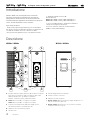
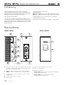
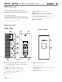
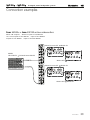
Descrizione
4
ITALIANO
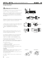
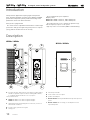
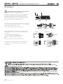
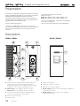
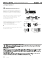
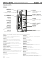
A Tromba a direttività costante (dispersione 60° H x 40° V) accoppiata
ad un driver a compressione da 2" in neodimio; bobina mobile
(da 4" per W28As, da 3" per W24As ) in piattina di
alluminio, centratore in kapton, diaframma in titanio.
B W28As: 2 woofer da 15", con magnete in neodimio.
W24As: 2 woofer da 12", con magnete in neodimio.
C Costruzione in multistrato di betulla ad incollaggio fenolico,
rinforzata internamente con angolari di acciaio.
D Griglia in acciaio (verniciatura epossidica).
E Tubi di accordo.
F Pratiche maniglie laterali per il trasporto.
G Pannello controlli e connessioni.
H Adattatore per asta di supporto.
I W28As / W24As: Binari per anelli di ancoraggio standard che con
sentono la sospensione della cassa.
L W28As / W24As: Anelli ad incasso che consentono di regolare
l'inclinazione della cassa sospesa.
W28As / W24As
POWER
I
0
SERIAL N.
FUSE
F 6,3AL
MAINS LINKMAINS INPUT
230V 50/60Hz
( 10K 0,775V RMS )
INOUT LINK
XLR BAL.
1 = GND
2 = HOT
3 = COLD
VOL.
100
H.F.
100
processor controlled active speaker system
1200W (900+300)
2A8
POUR ÉVITER TOUT RISQUE DE CHOC
ELECTRIQUE, NE PAS OUVRIR
POUR ÉVITER TOUT RISQUE DE FEU TOUJOURS REMPLACER
LE FUSIBLE PAR UN DE MÊMES CARACTERISTIQUES
CET APPAREIL DOIT ÊTRE RELIÉ A LA TERRE
TO PREVENT RISK OF FIRE ALWAYS REPLACE
FUSES WITH SAME TYPE AND RATING
THIS APPARATUS MUST BE EARTHED
TO PREVENT ELECTRIC SHOCK,
DO NOT REMOVE COVERS
CAUTION !
AVIS !
PUSH
3
12
NEUTRIK
B
L
D
E
H
A
C
G
L
Introduzione
W28As e W24As sono sistemi professionali ad altissime
prestazioni, progettati per rispondere alle situazioni più
impegnative sia del musicista che del service professionale,
rivelandosi ideali per applicazioni che richiedono alta pressione
sonora, massima denizione e suono cristallino.
Ogni sistema incorpora:
Componenti progettati appositamente per le caratteristiche
del sistema e perciò perfettamente integrati con l'elettronica ad
essi dedicata. L'utilizzo di woofer e driver in neodimio
offre la più elevata qualità in un peso estremamente ridotto.
2 amplicatori MosFet in classe AB.
Potenza di uscita:
W28As 900 + 300 W continui, 1200 + 350 W di picco
W24As 800 + 250 W continui, 1100 + 350 W di picco
2 processori indipendenti che ottimizzano la dinamica
e la risposta in frequenza del sistema.
Crossover elettronico attivo ad elevata pendenza
(24dB per ottava, Linkwitz-Riley).
F
I
W28As / W24As

28A - 24A bi-amped, active loudspeaker systems
POWER
I
0
SERIAL N.
FUSE
F 6,3AL
MAINS LINKMAINS INPUT
230V 50/60Hz
( 10K 0,775V RMS )
INOUT LINK
XLR BAL.
1 = GND
2 = HOT
3 = COLD
VOL.
100
H.F.
100
processor controlled active speaker system
1200W (900+300)
2A8
POUR ÉVITER TOUT RISQUE DE CHOC
ELECTRIQUE, NE PAS OUVRIR
POUR ÉVITER TOUT RISQUE DE FEU TOUJOURS REMPLACER
LE FUSIBLE PAR UN DE MÊMES CARACTERISTIQUES
CET APPAREIL DOIT ÊTRE RELIÉ A LA TERRE
TO PREVENT RISK OF FIRE ALWAYS REPLACE
FUSES WITH SAME TYPE AND RATING
THIS APPARATUS MUST BE EARTHED
TO PREVENT ELECTRIC SHOCK,
DO NOT REMOVE COVERS
CAUTION !
AVIS !
PUSH
3
12
NEUTRIK
5
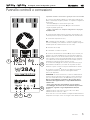
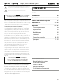
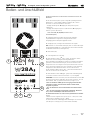
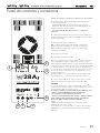
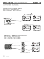
Pannello controlli e connessioni
ITALIANO
3
4
5
76
1
2
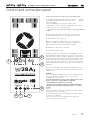
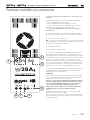
Il pannello controlli e connessioni è uguale per tutti e tre i modelli.
1 I sistemi acustici W28As e W24As sono dotati di prese XLR maschio
(OUT) e femmina (IN) collegate in parallelo: ciò semplica il collegamento
di più sistemi.
uscita mixer ingresso sistema acustico (presa 'IN')
uscita sistema acustico (presa 'OUT') ingresso del sistema da
collegare in parallelo (presa 'IN').
Vedere "connettori" ed "esempi di collegamento" alle pagine
19, 20, 21 e 22.
2 Volume generale (VOL). Permette di regolare i livelli di ingresso dei
2 nali di potenza incorporati, per adattarli al livello di uscita del mixer.
3 Volume delle frequenze alte (H.F.).
N.B: se utilizzate un mixer Montarbo, o comunque un mixer avente
livello di uscita 0dB, per un rendimento ottimale consigliamo di regolare
entrambi questi due volumi al massimo (in senso orario).
4 Interruttore di rete (I/0).
5 Portafusibile con fusibile incorporato.
6 Connettore di alimentazione PowerCon
®
tipo A (di colore blu), che
garantisce un contatto afdabile anche in presenza di forti vibrazioni.
Utilizzare solamente un cavo di alimentazione dotato di conduttore di
terra e riportante i marchi di sicurezza applicabili nel paese di impiego,
con conduttori di sezione adeguata alla corrente assorbita e spina di
alimentazione certicata per questo valore di corrente.
Per le istruzioni di cablaggio del connettore, fare riferimento a pag. 8.
Nell'installazione del diffusore, accertarsi che sia possibile accedere
facilmente a questo connettore e alla presa di alimentazione elettrica.
7 Connettore PowerCon
®
tipo B (di colore grigio) che permette il
collegamento (link) alla rete elettrica di altre apparecchiature
(max. 13,7A disponibili).
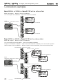
ATTENZIONE: la corrente massima che il connettore di alimentazione
PowerCon (6) può trasportare è pari a 20A. La corrente massima che
può essere fornita dal connettore 'AC LOOP OUT' (7) è pari a 13,7A.
Nel caso venga utilizzato il connettore 'AC Loop Out' (7) per
alimentare altre apparecchiature, è responsabilità dell'utente
vericare che:
- questo valore massimo di assorbimento non sia superato,
- l'assemblaggio del cordone di rete sia effettuato da personale
specializzato seguendo le regole impiantistiche nazionali.
Esempio:
3 W28As assorbono circa 19 A (6,3 A x 3) -> OK (19 A < 20 A)
4 W28As assorbono circa 25 A -> NO !
Nel secondo caso è necessario utilizzare 2 collegamenti di alimentazione
indipendenti (ad esempio: 2 linee che collegano 2 mod. W28As ciascuna).

28A - 24A bi-amped, active loudspeaker systems
Importante !
6
ITALIANO
Cura e manutenzione del prodotto
• Questo prodotto è stato progettato per essere utilizzato in climi
tropicali e particolarmente caldi.
• Non porre sulla cassa sorgenti di amme nude, quali candele accese.
• Posizionare la cassa lontano da fonti di calore (caloriferi o qualsiasi
altro oggetto che produca calore).
• Evitare di esporre la cassa alla radiazione solare diretta, ad eccessive
vibrazioni e ad urti violenti.
• Evitare l'uso ed il deposito dell'apparecchio in ambienti polverosi
o umidi: si eviteranno così cattivi funzionamenti e deterioramento
anticipato delle prestazioni.
• Evitare l'uso dell'apparecchio vicino a fonti di interferenze
elettromagnetiche (monitor video, cavi elettrici di alta potenza).
Ciò potrebbe compromettere la qualità audio.
• Nel caso in cui il sistema venga utilizzato all’aperto fare attenzione
a proteggerlo dalla pioggia.
• Proteggere l'apparecchio dal rovesciamento accidentale di liquidi
o sostanze di qualsiasi tipo. In particolare nelle condizioni di utilizzo
tipiche, prestare la massima attenzione alla collocazione dell'apparec-
chio onde evitare che il pubblico, i musicisti, i tecnici o chicchessia
possa poggiarvi sopra bicchieri, tazze, contenitori di cibo o di bevande,
posacenere o sigarette accese.
• Non togliere la griglia di protezione dalla cassa.
• Per rimuovere la polvere usare un pennello o un sofo d'aria,
non usare mai detergenti, solventi o alcool.
• Avere cura dei cavi di collegamento, avvolgerli evitando nodi
e torsioni.
• Non forzare i connettori ed i comandi.
• Accertarsi che l'interruttore di rete sia in posizione '0' (spento)
prima di effettuare qualsiasi collegamento.
• All’interno dell’apparecchio possono essere presenti potenziali elettrici
pericolosi anche quando l’interruttore di rete è in posizione '0' (spento)
e la spia luminosa è spenta. Prima di qualunque intervento di
manutenzione, scollegare il cavo di alimentazione dalla presa di rete
Collegamento alla rete
• Accertarsi che l'interruttore di rete sia in posizione "0".
• Accertarsi che la tensione di alimentazione corrisponda a quella
indicata sul pannello.
• Collegare il cavo di alimentazione ad una presa di corrente dotata
di contatto di terra di sicura efcienza. Utilizzare solamente il cavo di
alimentazione fornito con l’apparecchio o un altro dotato di contatto di
terra e riportante i marchi di sicurezza applicabili nel paese di impiego.
• Lasciare spazio sufciente per accedere alla presa di alimentazione
elettrica e al connettore di rete sul pannello posteriore.
All’interno dell’apparecchio possono essere presenti potenziali elettrici
pericolosi anche quando l’interruttore di rete è in posizione '0' (spento)
e la spia luminosa è spenta. Prima di qualunque intervento di
manutenzione, scollegare il cavo di alimentazione dalla presa di rete.
Collegamento al mixer
Se il mixer ha uscite bilanciate XLR: utilizzare dei normali connettori
XLR bilanciati.
Se il mixer ha uscite sbilanciate XLR e non è un Montarbo: è bene
accertarsi che le uscite XLR del mixer siano sbilanciate a norme IEC 268 e
cioé 1 = massa (GND), 2= caldo (HOT), 3=massa (GND).
Se il mixer ha uscite JACK bilanciate (Jack stereo): è possibile
utilizzare adattatori Jack stereo-XLR bilanciati, a norme IEC 268 e cioé
pin 1 = massa, pin 2 = punta, pin 3 = anello.
Se il mixer ha uscite JACK sbilanciate (Jack mono): è possibile
utilizzare adattatori Jack-XLR maschio sbilanciati a norme IEC 268 e
cioé pin 1 = massa, pin 2 = punta, pin 3 = massa.
Vedere "connettori" a pagina 37.
• Utilizzare sempre solo cavi SCHERMATI (cavi di segnale) di adeguata
sezione e di buona qualità.
• Prima di effettuare i collegamenti tra casse attive e mixer accertarsi
che tutti gli interruttori di rete siano spenti (0).
In tal modo si eviteranno fastidiosi rumori e picchi di segnale talvolta
pericolosi per le casse stesse.
Collegamento in parallelo di più sistemi
• Utilizzare sempre cavi SCHERMATI (cavi di segnale) di adeguata
sezione e di buona qualità. Collegare l’uscita (LINK OUT) del primo
sistema all’ingresso (LINK IN) del secondo, l’uscita (LINK OUT) del
secondo all’ingresso (LINK IN) del terzo ecc.
Vedere "esempi di collegamento" a pagina 38.

28A - 24A bi-amped, active loudspeaker systems
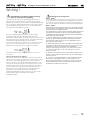
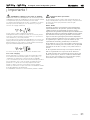
Sensibilità e clipping. Come evitare il clipping.
Ogni sistema amplicatore-altoparlante è caratterizzato da una
sensibilità di ingresso. La sensibilità è denita come il valore del segnale
di ingresso all'amplicatore che produce la massima potenza in uscita.
Aumentando il segnale oltre tale valore, infatti, non si ottiene una
maggiore potenza di uscita, ma soltanto un fenomeno di distorsione
detto 'clipping' (saturazione).
In questa situazione l'altoparlante lavora in modo improprio. Si hanno
delle sovraescursioni e una dissipazione anomala nella bobina mobile,
che si surriscalda e può rompersi. I processori attivi possono evitare solo
parzialmente il clipping, abbassando il guadagno dell'amplicatore.
È possibile, in casi estremi, oltrepassare anche questo tipo di protezione.
Ciò che il processore non può modicare è un'onda che arrivi già
distorta in ingresso all'amplicatore.
Gli effetti di un segnale di questo tipo sono gli stessi descritti sopra.
Come evitare il clipping
Il metodo più semplice sta nel controllare i livelli della catena del segna-
le. Partendo dal canale del mixer bisogna impostare i controlli (gain ed
equalizzatori) in modo tale che il VU-meter del PFL non oltrepassi mai
(o solo occasionalmente) gli 0dB o, in mixer più semplici, che la spia
'clip' o 'peak' non si accenda mai (o solo occasionalmente).
Se si oltrepassano tali livelli occorre diminuire il gain del canale.
Una volta impostato il giusto mix, bisogna fare attenzione ad imposta-
re il livello di uscita in modo tale che il VU-meter non oltrepassi mai il
livello della sensibilità di ingresso della cassa amplicata o del nale di
potenza. Nel caso dei modelli W28As e W24As la sensibilità di ingresso
è 0dB .
7
ITALIANO
Importante !
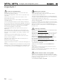
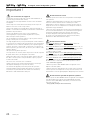
Sospensione dei sistemi
W28As - W24As
Incorporano su entrambi i lati un binario per anello di ancoraggio
standard per la sospensione del cabinet e sulla parte posteriore 2 anelli
ad incasso che ne consentono l'inclinazione secondo le necessità.
W28As - W24As
Ricordare sempre che nel caso di installazione sospesa, questa
deve avvenire sotto la responsabilità dell'installatore, nel rispetto
di tutte le precauzioni e le norme di sicurezza applicabili nel caso
specico. Non è possibile fornire regole e consigli dettagliati
e validi per tutti i casi, ma ricordiamo che, per la sicurezza
dell'installazione, occorre seguire alcune precauzioni importanti:
1 - Per la sospensione, utilizzare accessori (conformi alle nome
di sicurezza applicabili nel paese di impiego) il cui produttore
ne dichiari e ne garantisca la portata.
2 - Non usare un solo accessorio per la sospensione (ad esempio,
una sola catena), ma almeno due, di portata adeguata. In caso di
rottura di uno di essi, l’altro sarà in grado di sostenere il sistema.
3 - Non agganciare mai un diffusore a quello superiore. Ogni
diffusore deve essere agganciato ai sostegni autonomamente.
4 - Vericare sempre che la struttura cui i diffusori sono sospesi
sia in grado di sopportarne il peso, anche in condizioni avverse.
Considerare l’effetto di altri carichi (ad esempio, il vento nelle
installazioni all’aperto).

28A - 24A bi-amped, active loudspeaker systems
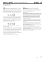
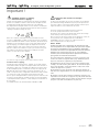
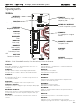
connettore chiuso
corpo
bussolaserracavo
cavo
morsetti
vista interna
inserto
fili
cavo
fili
20 mm
8 mm
Importante !
8
ITALIANO
Inserimento Disinserimento
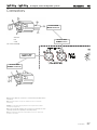
Cablaggio del cavo di alimentazione sul
connettore PowerCon
®
(fornito con l'apparecchio).
L'assemblaggio del cordone di rete deve essere effettuato da personale
specializzato seguendo le regole impiantistiche nazionali.
Spelare il cavo per una lunghezza di 20 mm ed ogni singolo lo per una
lunghezza di 8 mm. Consigliamo l'utilizzo di un cavo di alimentazione
con conduttori aventi sezione di almeno 2,5 mm
2
(i morsetti dell'in-
serto possono comunque portare un cavo con li aventi sezione no a
4mm
2
/12AWG).
Inlare il cavo prima nella bussola poi nel serracavo (bianco per un cavo
con diametro 5÷11mm; nero per un cavo con diametro 9.50 ÷ 15mm).
Effettuare i collegamenti dei conduttori ai morsetti dell'inserto.
I conduttori potranno essere serrati nei morsetti oppure saldati, facendo
però sempre attenzione ai simboli che compaiono sul connettore stesso:
L (Line - corrispondente al lo di colore marrone),
N (Neutro - corrispondente al lo di colore azzurro) e
(Terra - corrispondente al lo di colore giallo e verde).
Effettuati i collegamenti dei li sull'inserto inlare il cavo nel corpo e
avvitare quest'ultimo alla bussola utilizzando una chiave da 3/4"con
una coppia di serraggio minima pari a 2,5Nm.
Il cavo utilizzato per il cablaggio deve essere conforme alle normative
vigenti nel paese di utilizzo. La sezione minima dei conduttori è:
2,5mm
2
per cavo collegato al connettore NC3 MPA (AC Line In)
1,5mm
2
per cavo collegato al connettore NC3 MPB (AC Loop Out)
La spina di corrente sul lato opposto deve essere certicato per una
corrente pari almeno a 20A (es: IEC309 32 A).
Quando, per qualunque motivo, il cavo di alimentazione risulta danneg-
giato, occorre provvedere alla sua riparazione prima di riutilizzarlo.
Per la sostituzione del cavo:
1 - scollegare il cavo completamente
2 - svitare la bussola (chiave 3/4")
3 - mediante cacciavite, scollegare i 3 conduttori dal connettore.
4 - rimuovere serracavo e bussola dal cavo
5 - utilizzando un nuovo cavo conforme ai requisiti indicati, procedere
al montaggio del connettore (vedi sopra)
ATTENZIONE:
- Prima di collegare e/o scollegare il connettore Powercon, è necessario
spegnere tutte le apparecchiature alle quali è collegato il cavo e
disconnettere il cavo dalla rete elettrica.
- Occorre utilizzare sempre questa procedura anche quando si procede
allo spostamento delle casse.
Per scolegare o collegare il connettore operare come indicato nel dise-
gno qui a lato.

28A - 24A bi-amped, active loudspeaker systems
__________________________________________
__________________________________________
__________________________________________
__________________________________________
__________________________________________
__________________________________________
__________________________________________
__________________________________________
__________________________________________
__________________________________________
__________________________________________
10
10
11
12 - 14
33 - 43
34
35
36
37
38 - 40
41 - 42
ENGLISH
9
ENGLISH
INDEX
Introduction
Description
Control and connection panel
Important !!!
Appendix
Technical Specications
Response curve
Block diagram
Connectors
Connection examples
Spare parts
The lighting ash with arrowhead symbol within an equilateral triangle, is intended to alert
the user to the presence of uninsulated 'dangerous voltage' within the product's enclosure,
that may be of sufcient magnitude to constitute a risk of electric shock to humans.
The exclamation point within an equilateral triangle, is intended to alert the user to the
presence of important operating and maintenance (servicing) instructions.
PACKAGE CONTENTS
Bi-amplied active system
PowerCon
®
connector
Owner’s manual
Warranty certicate
CE declaration of conformity
IMPORTANT ! SAFETY INSTRUCTIONS
WARNING
In order to protect your own and others' safety and to avoid invalidation
of the warranty of this product, please read this section carefully
before operating this product.
- This product has been designed and manufactured for being operated as active
speaker system in the applications tipical of a sound reinforcement system or of a
sound recording system. Operation for purposes and applications other than these
has not been covered by the manufacturer in the design of the product, and is
therefore to be undertaken at end user's and/or installer's sole risk and responsability.
- This unit conforms to Class I insulation, and for safe use it is required that the
protective earth contact is connected to a grounded (earthed) outlet.
TO AVOID THE RISK OF FIRE AND/OR ELECTRIC SHOCK:
• Never expose this product to rain or moisture, never use it in proximity of water
or on a wet surface. Never let any liquid, as well as any object, enter the product.
In case, immediately disconnect it from the mains supply and refer to servicing before
operating it again. Never place burning candles or other sources of open ame on
top of the device.
• Before connecting this product to the mains supply, always make sure that the
voltage on the mains outlet corresponds to that stated on the product.
• This product must be connected only to a grounded mains outlet complying to
the safety regulations in force via the supplied power cable. In case the power cable
needs to be substituted, use exclusively a cable of the same type and characteristics.
• This device is connected to the power line even when the mains switch is in the
O (off) position and the power indicator is off. As long as it is plugged in there are
dangerous electrical potentials inside the device, so, before undertaking any sort of
maintenance work etc., always make sure it has been unplugged from the mains
socket.
• Never place any object on the power cable. Never lay the power cable on a
walkway where one could trip over it. Never press or pinch it.
• Never install the product without providing adequate airow to cool it.
Never obstruct the air intake openings on it. Leave enough room to get to the
mains power socket and the mains connector on the back panel.
• In case the external fuse needs replacement, substitute it only with one of the
same type and rating, as stated on the product.
• Always make sure the Power switch is in its '0' (= off) position before doing any
operation on the connections of the product.
• Before attempting to move the product after it has been installed, remove all
the connections.
• To disconnect the power cable of this product from the mains supply never pull
the cable directly. Hold the body of the plug rmly and pull it gently from the mains
supply outlet.
CAUTION!
This product does not contain user serviceable parts.
To prevent re and/or electrical shock, never disassemble it or
remove the rear panel. For maintenance and servicing always
refer to the ofcial Montarbo Distributor in your Country or
to qualied personnel specically authorised by the Distributor.
- Before placing the product on a surface of any kind, make sure that its shape and
load rating safely match the product size and weight. When installing the speaker
system on a stand, use a stable stand that will t in the adapter and may carry the
loudspeaker weight.
If you wish to suspend the system, follow the directions at page 13.
- To avoid shocks, kicks, or whatever action, always reserve a protected area with
no access to unqualied personnel as installation site of the product.
In case the product is used near children and animals closest supervision is necessary.
- This product can generate very high acoustic pressures which are dangerous for the
hearing system. Always avoid operation at loud levels if anyone is excessively near to
the product (at least 1 m of distance).
Never expose children to high sound sources.

28A - 24A bi-amped, active loudspeaker systems
10
ENGLISH
Introduction
Ideally suited to applications requiring high sound pressure
levels, maximum denition and clean sound, W28As and W24A
professional loudspeaker systems provide outstanding sound
performance in the most diverse situations
Each system is equipped with:
The custom made neodymium-based transducers combine high
performance with great weight saving and operate in complete
synergy with the dedicated electronic circuitry.
Two class A-B MosFet power ampliers.
Output powers:
W28As 900 + 300 W continuous, 1200 + 350 W peak
W24As 800 + 250 W continuous, 1100 + 350 W peak
Two independent processors optimize the dynamic range
and the frequency response of the system.
High slope active crossover lter (24dB/oct Linkwitz-Riley).
A Constant directivity, high frequency horn (dispersion 60°H x 40°V)
with 2" neodymium compression driver featuring (4" in W28As,
3" in W24As) aluminum at wire voice coil, kapton
former, titanium dome.
B W28As: 2 x 15" woofers with neodymium magnet
W24As: 2 x 12" woofers with neodymium magnet
C High grade phenyl-glued multiply birch construction, reinforced
with internal steel braces.
D Powder coated, perforated steel grid.
E Tuning ports.
F Side transport handles.
G Controls and connections panel.
H Speaker stand adaptor.
I W28As / W24As: Industry standard aluminium y-track suspension
system.
L W28As / W24As: Recessed rings, for tilt adjustment of the
suspended speaker.
Description
W28As / W24As
POWER
I
0
SERIAL N.
FUSE
F 6,3AL
MAINS LINKMAINS INPUT
230V 50/60Hz
( 10K 0,775V RMS )
INOUT LINK
XLR BAL.
1 = GND
2 = HOT
3 = COLD
VOL.
100
H.F.
100
processor controlled active speaker system
1200W (900+300)
2A8
POUR ÉVITER TOUT RISQUE DE CHOC
ELECTRIQUE, NE PAS OUVRIR
POUR ÉVITER TOUT RISQUE DE FEU TOUJOURS REMPLACER
LE FUSIBLE PAR UN DE MÊMES CARACTERISTIQUES
CET APPAREIL DOIT ÊTRE RELIÉ A LA TERRE
TO PREVENT RISK OF FIRE ALWAYS REPLACE
FUSES WITH SAME TYPE AND RATING
THIS APPARATUS MUST BE EARTHED
TO PREVENT ELECTRIC SHOCK,
DO NOT REMOVE COVERS
CAUTION !
AVIS !
PUSH
3
12
NEUTRIK
B
L
D
E
H
A
B
C
G
L
F
I
W28As / W24As

28A - 24A bi-amped, active loudspeaker systems
11
ENGLISH
POWER
I
0
SERIAL N.
FUSE
F 6,3AL
MAINS LINKMAINS INPUT
230V 50/60Hz
( 10K 0,775V RMS )
INOUT LINK
XLR BAL.
1 = GND
2 = HOT
3 = COLD
VOL.
100
H.F.
100
processor controlled active speaker system
1200W (900+300)
2A8
POUR ÉVITER TOUT RISQUE DE CHOC
ELECTRIQUE, NE PAS OUVRIR
POUR ÉVITER TOUT RISQUE DE FEU TOUJOURS REMPLACER
LE FUSIBLE PAR UN DE MÊMES CARACTERISTIQUES
CET APPAREIL DOIT ÊTRE RELIÉ A LA TERRE
TO PREVENT RISK OF FIRE ALWAYS REPLACE
FUSES WITH SAME TYPE AND RATING
THIS APPARATUS MUST BE EARTHED
TO PREVENT ELECTRIC SHOCK,
DO NOT REMOVE COVERS
CAUTION !
AVIS !
PUSH
3
12
NEUTRIK
Control and connection panel
3
4
5
76
1
2
Controls and connections are the same for the three models.
1 The W28As and W24As speaker systems are equipped with XLR
male (OUT) and female (IN) parallel connected sockets allowing
easier daisy-chaining.
Mixer output Input ('IN' socket) of the speaker system
Output ('OUT' socket) of the speaker system Input ('IN' socket) of
the speaker system to be connected in parallel.
See 'connectors' and 'connection examples' at pages 19, 20, 21
and 22.
2 Main volume (VOL). Adjusts the input levels of the two built-in
ìpower ampliers to adapt them to the output level of the mixer.
3 High frequencies level control (H.F.).
Note: if you are using a Montarbo mixer (or any mixer having an
output level of 0dB) for optimum performance it is advisable to set
both controls fully clockwise (to their maximum settings).
4 POWER / 0 - I: Mains power on/off switch.
5 Fuse holder with built-in fuse.
6 Mains supply inlet socket with type A PowerCon
®
(blue) connector,
which guarantees a reliable, vibration-proof contact. Use only a mains
cable with suitable conductors capable of handling the current involved,
equipped with a ground conductor, marked with the applicable, country
specic, safety approvals and tted with a power plug certied for the
actual current value. Refer to page 14 for connector wiring instructions.
When installing make sure that it is easy to get to this socket and to the
mains plug.
7 Power 'AC LOOP OUT' socket (type B gray PowerCon
®
connector)
that allows you to link other devices to the mains power (max. current
available: 13.7 A).
CAUTION
The power supply PowerCon® socket (6) is rated for a 20 A maximum
current. The maximum current that may be sourced from the
'AC LOOP OUT' socket is 13.7 A.
If the 'AC LOOP OUT' (7) socket is used to supply power to other
devices, it is the user's responsibility to verify that:
- this maximum current drain is not exceeded,
- the power cord assembly is made by a qualied techncian in
compliance with the national regulations in force for electrical
systems.
Example:
Three model W28As speakers have a maximum current drain of about
19 A (6.3 A x 3) > OK (19 A < 20 A).
Four model W28As speakers have a maximum current drain of about
25 A (6.3 A x 4) > NOT OK!
In this case you must use two independent power supply cables.
(two lines, each powering two W28As).

28A - 24A bi-amped, active loudspeaker systems
Important !
12
ENGLISH
Product care and maintenance
• This product has been designed for use in tropical climates and
particularly warm weather conditions.
• Never place burning candles or other sources of open ame on top
of the device.
• Never expose the enclosure to heat sources (heaters or other
products that produce heat).
• Never expose the enclosure to direct sunlight, excessive vibrations
or mechanical shocks.
• Avoid operating and storing the enclosure in damp or dusty places:
this may lead to malfunctions and premature degrading of specications.
• Avoid using the enclosure close to strong sources of electromagnetic
interferences (e.g. video monitors, high power electrical cabling).
This may lead to degradation of audio quality.
• When setting up the system up outdoors, be sure to protect it
against rain.
• Care should be taken so that objects do not fall and liquid is not
spilled onto the enclosure. In public event don't let people, musicians,
technicians or anyone put glasses, cups, ashtrays or cigarettes on the
enclosure.
• Always leave the protective grid mounted on the enclosure.
• Use a soft brush or a jet of air to clean the enclosure. Do not use
alcohol, solvents or detergents.
• Take care of your connector cables. Make sure that they are not
damaged, knotted or twisted.
• Do not force connectors and controls.
• Make sure the mains power switch is off ('0') before starting any con-
nection.
• As long as it is plugged in there can be dangerous electrical potentials
inside the device, so, before undertaking any sort of maintenance work
etc., always make sure it has been unplugged from the mains socket.
Mains power connection
• Make sure the mains power switch is off ('0').
• Check that mains voltage corresponds to the voltage indicated
on the panel, under the mains socket.
• Use only the factory supplied mains cable or, if a different plug style
is needed, a suitable cable with a ground connection and marked with
the safety approvals valid in the country of use.
• Leave enough room to get to the mains power socket and the mains
connector on the back panel.
As long as it is plugged in there can be dangerous electrical potentials
inside the device, even when the mains switch is in the '0' (off) position
and the power indicator is off so, before undertaking any sort of
maintenance work etc., always make sure it has been unplugged from
the mains socket
Connection to the mixer
If the mixer has XLR balanced outputs: use standard balanced XLR
connectors.
If the mixer has XLR unbalanced outputs: in this case, unless using
a Montarbo mixer, make sure that the XLR outputs on the mixer are
unbalanced to IEC 268 standard 1 = GND, 2 = HOT, 3 = GND.
If the mixer has JACK balanced outputs (stereo jacks): it is
possible to use stereo jack-XLR adapters, wired according to IEC 268
pin 1 = ground (sleeve), pin 2 = tip, pin 3 = ring.
If the mixer has JACK unbalanced outputs (mono jacks):
use suitable Jack-XLR male adapters unbalanced according to IEC 268
pin 1 = ground, pin 2 = tip, pin 3 = ground.
See 'connectors' at page 37.
• Always use only heavy gauge, high quality SHIELDED cables
(signal cables).
• Always make sure that the mixer and the powered enclosures are
switched off before connecting them.
This will to avoid annoying noises and signal peaks, which can also be
dangerous for the enclosures themselves.
Parallel connection of two or more systems
• Always use only heavy gauge, high quality SHIELDED cables (signal
cables). Connect the LINK OUT socket of the rst system to the LINK IN
socket the second system and the LINK OUT of the second system to
the LINK IN of the third, and so on.
See 'connection examples' at page 38.

28A - 24A bi-amped, active loudspeaker systems
Input sensitivity and clipping. How to avoid clip-
ping
Every amplied speaker system is characterized by a value of input
sensitivity. The sensitivity is dened as the value of the amplier's input
signal that will result in maximum power output. An increase in input
signal over that threshold will result, not in increased power, but in a
distortion phenomenon called 'clipping' (output stage saturation).
In this condition, the speaker will operate improperly. The diaphragm
will exceed it's excursion limits, and the voice coil will overheat beyond
it's thermal limits, resulting in overheating and premature failure.
The active processors will help in avoiding clipping, by reducing the
amplier gain and thus the input sensitivity, but this type of protections
may be overridden in very extreme conditions.
What the active processor cannot modify is a signal that is distorted
before getting to the active speaker's input.
The effects of this type of signal are the same as described above.
How to avoid clipping
The simplest way to avoid clipping is to check each level in the signal's
chain. Start from each input channel of the mixer and adjust the gain
control and the equalizer's controls so that the PFL meter will never (or
only occasionally) indicate more than 0dB. In simpler mixers, check that
the 'clip' or 'peak' indicator is always off, or blinks only occasionally.
If these levels are exceeded, reduce the channel's input gain.
Once the desired mix is obtained, adjust the output level so that it never
exceeds the active speaker's or the power amplier's input sensitivity,
as displayed on the master output VU-meter.
In models W28As and W24As the input sensitivity is 0dB.
13
ENGLISH
Important !
Hanging the speakers. Tips and warnings.
W28As - W24As
Both sides of their cabinet embody a slide guide for standard anchor
ring to allow the loudspeaker suspension.
On the rear side there are
two recessed rings allowing tilt adjustment.
W28As - W24As
Please bear in mind that all hanging installation jobs are carried
out under the sole responsibility of the person doing the actual
work and must be done in full compliance with all the applicable
safety rules and regulations. We do not attempt to provide
detailed guidelines for all the potential ways in which these
extremely exible systems can be installed, but do want to
remind you that to ensure a safe installation, it is necessary
to adhere to the following:
1 - When hanging the speakers, use only means of suspension
(in accordance with the safety regulation valid in the country
of use) having a carrying capacity rated and guaranteed by the
manufacturer.
2 - Never depend on only one means of suspension for hanging
speakers (for example one chain); always use at least two of
them and make sure they are sufciently strong. So, if one fails
the other will sustain the load.
3 - Never hook a speaker to the one above.
Each speaker must be individually hooked to the supports.
4 - Always make sure that the truss structure intended to support
the speakers is sturdy enough to hold their weight, even under
stressful, adverse conditions.
Always consider the effect of additional loads (for example, the
wind in case of outdoor installations).

28A - 24A bi-amped, active loudspeaker systems
Important !
power con
®
connector
housing
bushingchuck
cable
setscrews
inside view
insert
wires
cable
wires
20 mm
8 mm
14
ENGLISH
Plugging Unplugging
Wiring of the power cable for the PowerCon
®
connector (supplied with the unit).
The power cord assembly must be made by a qualied techncian in
compliance with the national regulations in force for electrical systems.
Strip the cable for 20 mm of length and strip each wire for 8 mm of
length. We suggest to use a power cable with 2,5 mm
2
section
wires (the insert terminals can however support a cable with wires up
to a section of 4 mm
2
/12AWG).
Insert the power cable into the bushing and into the chuck (white
chuck for a cable diameter of 5 ÷ 11 mm; black chuck for a cable
diameter of 9.50 ÷ 15 mm). Insert the wires into the terminals and
fasten the clamping device by a at screw driver.
The wire ends can be clamped in or soldered to the terminal, always
paying attention to the symbols shown on the connector:
L (Live - corresponding to the brown wire),
N (Neutral - corresponding to the light blue wire) and
(Ground - corresponding to the yellow and green wire).
Once the wires have been connected to the insert, lead the cable
through the housing and screw down the bushing by means of a 3/4"
fork wrench (min. torque 2.5 Nm / 1.8 lb-ft).
The cable must comply with the applicable, country specic, safety
regulations.
The minimum conductor size must be:
2.5 mm
2
(13 AWG) for the cable wired to the NC3 MPA (AC line in) plug
1.5 mm
2
(15 AWG) for the cable wired to the NC3 MPB (AC loop out)
plug.
The mains power plug on the other end of the cable must be certied
for a current equal to 20A at least (eg: IEC309 32A).
When, for any reason, the power cable show signs of damage, it is
mandatory to replace or repair it before any further use.
To replace the cable:
1 - disconnect the cable at both ends
2 - unscrew the bushing (3/4" wrench)
3 - using a screwdriver, disconnect all three conductors from the insert
4 - remove the chuck and the bushing from the cable
5 - using a new cable, complying with the previous reported require-
ments, proceed with the connector's assembly, as described above.
CAUTION:
- Before plugging and/or unplugging the PowerCon connector, it is
mandatory to switch off all the equipment that is connected to the
cable and to disconnect the cable from AC mains.
- Follow this procedure also when the speakers must be moved.
Operate as illustrated in the side drawing when you have to plug and/or
unplug the connector.

28A - 24A bi-amped, active loudspeaker systems
15
DEUTSCH
Das Blitzsymbol mit Pfeilspitze innerhalb eines gleichschenkligen Dreiecks warnt den
Benutzer vor dem Vorhandensein nicht isolierter gefährlicher Netzspannungen im
Inneren des Geräts, die so stark sein können, dass für Menschen die Gefahr eines
Stromschlags besteht.
Das Ausrufezeichen innerhalb eines gleichschenkligen Dreiecks macht den Benutzer
auf das Vorhandensein wichtiger Betriebs- und Wartungsanleitungen aufmerksam.
WICHTIG ! Sicherheitsvorschriften
ACHTUNG
Im Interesse Ihrer eigenen Sicherheit und der Sicherheit anderer
und um die Garantie nicht zu gefährden, sollte der vorliegende
Abschnitt vor Gebrauch des Produkts aufmerksam gelesen werden.
- Dieses Gerät wurde für den Gebrauch als Aktivlautsprechersystem im Rahmen
typischer Anwendungen von Verstärkungssystemen und/oder Tonaufnahmesystemen
entwickelt und hergestellt. Der Gebrauch zu anderen als den genannten Zwecken ist
vom Hersteller nicht vorgesehen und erfolgt somit unter direkter Verantwortung des
Benutzers/Installateurs.
- Dieses Gerät entspricht der Isolierungsklasse 1 (Schutzerdung ist unbedingt
erforderlich).
Zur Vermeidung der Gefahr von Bränden oder elektrischen Schlägen:
• Dieses Produkt nicht Regen oder Feuchtigkeit aussetzen und nicht in der Nähe von
Wasser betreiben. Verhindern, dass in das Gerät Flüssigkeiten oder Gegenstände
eindringen. Sollte dies dennoch geschehen, unverzüglich das Gerät vom Stromnetz
abnehmen und vor der erneuten Inbetriebnahme durch einen qualizierten Service-
techniker überprüfen lassen. Stellen Sie keine offenen Flammen, beispielsweise
angezündete Kerzen, auf das Gerät.
• Vor dem Anschluss an das Stromnetz sicherstellen, dass die Netzspannung mit der
auf dem Gerät angegebenen Nennspannung übereinstimmt.
• Das Gerät ausschließlich mit dem mitgelieferten Netzkabel an eine Steckdose mit
Schutzkontakt anschließen, die den geltenden Sicherheitsvorschriften entspricht.
Muss das Netzkabel ersetzt werden, ausschließlich ein Netzkabel mit identischen
Eigenschaften verwenden.
• Selbst wenn der Netzschalter sich in der Stellung '0' (aus) bendet, ist das Gerät
nicht vollständig vom Netz getrennt und kann gefährliche elektrische Potentiale
aussenden. Vor jedem Wartungseingriff ist das Gerät vom Stromnetz zu trennen
(Netzkabel ausstecken)
• Zum Ausstecken des Netzkabels aus der Steckdose keinesfalls am Netzkabel ziehen,
sondern das Kabel stets direkt am Stecker anfassen.
• Keine Gegenstände auf dem Netzkabel abstellen. Das Netzkabel so verlegen, dass
es kein Hindernis darstellt und keine Stolpergefahr besteht. Das Netzkabel nicht quet-
schen und nicht darauf treten.
• Bei der Installation genug freien Raum um das Gerät lassen, um eine ausreichende
Luftzirkulation für die Kühlung zu gewährleisten. Die Lüftungs- und Ansaugöffnungen
nicht verdecken. Genug freien Raum lassen um die Steckdose und den Netzstecker
auf der Rückeite zu erreichen.
• Muss die externe Sicherung ausgetauscht werden, ausschließlich eine Sicherung
mit identischen Eigenschaften gemäß den Angaben auf dem Gerät verwenden.
• Vor dem Anschluss des Geräts sicherstellen, dass sich der Ein/Aus-Schalter in
Schaltstellung '0' bendet.
• Vor dem Transport des bereits installierten oder bereits in Betrieb bendlichen
Geräts zunächst alle Anschlusskabel abnehmen.
ACHTUNG!
Dieses Gerät enthält keine Teile, bei denen ein direkter Eingriff seitens des
Benutzers vorgesehen ist. Das Gerät keinesfalls auseinanderbauen oder
die Rückwand abnehmen, um die Gefahr von Bränden und elektrischen
Schlägen zu vermeiden. Für Wartungs- und Reparatureingriffe aller Art
wenden Sie sich stets an das Unternehmen Elettronica Montarbo srl und/
oder qualizierte Fachtechniker, die vom Unternehmen genannt werden.
- Bei der Vorbereitung des Geräts auf den Betrieb sollte sichergestellt werden, dass
die Form und die Tragfähigkeit der Auageäche für die Aufstellung desselben
geeignet sind. Sollte die Lautsprecherbox auf einem Stativ installiert werden, so
sollte dieses hinsichtlich der Tragfähigkeit dem Gewicht des Produktes entsprechend
ausgelegt sein, und in den hierfür vorgesehenen Adapter eingesteckt werden.
Wird das System aufgehängt, müssen die auf Seite 19 aufgeführten
Vorschriften beachtet werden.
- Zur Vermeidung von Stößen, Tritten und sonstigen gewaltsamen Einwirkungen das
Gerät nur an einem geschützten und Unbefugten nicht zugänglichen Ort aufstellen.
Wenn das Gerät in Gegenwart von Kindern oder Haustieren betrieben wird, ist eine
strikte Überwachung erforderlich.
- Dieses Gerät kann sehr hohe Schalldruckwerte erzeugen, die zu Gehörschäden
führen können. Daher sind hohe Lautstärkepegel zu vermeiden, wenn sich das
Publikum in großer Nähe zum Gerät bendet. Sicherstellen, dass ein Abstand von
mindestens 1m zwischen Gerät und Publikum gewährleistet ist.
Niemals Kinder starken Schallemissionen aussetzen !
__________________________________________
__________________________________________
__________________________________________
__________________________________________
__________________________________________
__________________________________________
__________________________________________
__________________________________________
__________________________________________
__________________________________________
__________________________________________
INHALTSVERZEICHNIS
Einführung
Beschreibung
Bedien- und Anschlußfeld
Wichtig !!!
Appendix
Technische Daten
Frequenzkurve
Blockdiagramm
Anschlüsse
Anschlussbeispiele
Ersatzteile
16
16
17
18 - 19
33 - 43
34
35
36
37
38 - 40
41 - 42
DEUTSCH
PACKUNGSINHALT
Aktives Lautsprechersystem
PowerCon
®
Netz Kabelstecker
Bedienungsanleitung
Garantiebescheinigung
EG-Konformitätserklärung

28A - 24A bi-amped, active loudspeaker systems
16
DEUTSCH
Einführung
W28As und W24As wurden für Leistungen auf höchstem
Niveau entwickelt. Beide Systemen stellen die ideale Lösung für
Anwendungen dar, die einen hohen Schalldruck, eine maximale
Auösung und einen kristallklaren Ton erfordern.
Beide Systemen verfügen über:
Nach Montarbo-Angaben speziell gefertigten Komponenten, die
mit der für sie vorgesehenen Elektronik perfekt übereinstimmen.
Sowohl der Tieftöner als auch der Mittel/Hochtontreiber sind aus
NEODYM gefertigt und bieten höchste Qualität bei einem äußert
geringen Gewicht.
2 MosFet-Verstärker der Klasse AB.
Ausgangsleistungen:
W28As 900 + 300 W Dauerleistung, 1200 + 350 W Spitzenleistung
W24As 800 + 250 W Dauerleistung, 1100 + 350 W Spitzenleistung
z
2 unabhängige Prozessoren optimieren den Frequenzgang
und die Dynamik des Systems.
Elektronische aktive Frequenzweiche (24dB/oct., Linkwitz-Riley).
A 2"-Neodym-Kompressionstreiber (Titanmembrane; 4" Schwingspule
bei W28A, 3" Schwingspule bei W22A und W24A) und Horn mit
abgeregeltem Abstrahl (60°H x 40°V).
B W28As: Zwei 15" Hochleistungs-Tieftöner mit Neodymmagnet.
W24As: Zwei 12" Hochleistungs-Tieftöner mit Neodymmagnet
C Konstruktion aus phenolverleimtem Birkenholz, intern verstärkt
mit Stahlwinkeln.
D Stahlgitter mit Epoxydharzbeschichtung.
E Reexöffnungen.
F Praktische seitliche Tragegriffe für den Transport.
G Bedien- und Anschlußfeld.
H Adapter für Hochständer.
I W28As / W24As: Schiene für den Standard-Verankerungsring zur
Aufhängung der Lautsprecherbox.
L W28As / W24As: Versenkter Ring zur Einstellung des
Neigungswinkels der Lautsprecherbox.
Beschreibung
W28As / W24As
POWER
I
0
SERIAL N.
FUSE
F 6,3AL
MAINS LINKMAINS INPUT
230V 50/60Hz
( 10K 0,775V RMS )
INOUT LINK
XLR BAL.
1 = GND
2 = HOT
3 = COLD
VOL.
100
H.F.
100
processor controlled active speaker system
1200W (900+300)
2A8
POUR ÉVITER TOUT RISQUE DE CHOC
ELECTRIQUE, NE PAS OUVRIR
POUR ÉVITER TOUT RISQUE DE FEU TOUJOURS REMPLACER
LE FUSIBLE PAR UN DE MÊMES CARACTERISTIQUES
CET APPAREIL DOIT ÊTRE RELIÉ A LA TERRE
TO PREVENT RISK OF FIRE ALWAYS REPLACE
FUSES WITH SAME TYPE AND RATING
THIS APPARATUS MUST BE EARTHED
TO PREVENT ELECTRIC SHOCK,
DO NOT REMOVE COVERS
CAUTION !
AVIS !
PUSH
3
12
NEUTRIK
B
L
D
E
H
A
B
C
G
L
F
I
W28As / W24As

28A - 24A bi-amped, active loudspeaker systems
DEUTSCH
17
POWER
I
0
SERIAL N.
FUSE
F 6,3AL
MAINS LINKMAINS INPUT
230V 50/60Hz
( 10K 0,775V RMS )
INOUT LINK
XLR BAL.
1 = GND
2 = HOT
3 = COLD
VOL.
100
H.F.
100
processor controlled active speaker system
1200W (900+300)
2A8
POUR ÉVITER TOUT RISQUE DE CHOC
ELECTRIQUE, NE PAS OUVRIR
POUR ÉVITER TOUT RISQUE DE FEU TOUJOURS REMPLACER
LE FUSIBLE PAR UN DE MÊMES CARACTERISTIQUES
CET APPAREIL DOIT ÊTRE RELIÉ A LA TERRE
TO PREVENT RISK OF FIRE ALWAYS REPLACE
FUSES WITH SAME TYPE AND RATING
THIS APPARATUS MUST BE EARTHED
TO PREVENT ELECTRIC SHOCK,
DO NOT REMOVE COVERS
CAUTION !
AVIS !
PUSH
3
12
NEUTRIK
Bedien- und Anschlußfeld
3
4
5
76
Bedienungselemente und Anschluße sind identisch für die drei
Modellen.
1 Das Anschlussfeld jedes Systems verfügt über parallelgeschaltene
XLR-Buchsen - sowohl männlich (OUT) als weiblich (IN) - die den
Anschluss von weiteren Aktivboxen erleichtern.
Ausgang des Mischpults Eingang des Lautsprechersystems
('IN'-Buchse).
Ausgang des Lautsprechersystems ('OUT'-Buchse) Eingang eines
weiteren Systems ('IN'-Buchse).
Siehe Seiten 37, 38, 39, 40 (Anschlusse und
Anschlußbeispiele).
2 Eingangspegelkontrolle (VOL). Damit kann die Eingangs-
empndlichkeit der integrierten Leistungsendstufe an den
Ausgangspegel des Mischpults angepaßt werden.
3 Klangregler (H.F.). Verringert den Höhenanteil des Signals.
N.B: Benutzen Sie ein Montarbo-Mischpult, bzw. ein anderes Mischpult
mit Ausgangspegel 0dB, ist es empfehlenswert diese beiden Lautstärke
auf Maximal einzustellen (im Uhrzeigersinn).
4 Netzschalter (I/0).
5 Sicherungshalter mit Sicherung.
6 Netzverbinder PowerCon
®
(Typ A - blau), der auch bei starken
Vibrationen einen zuverlässigen Kontakt gewährleistet.
Nur ein Netzkabel mit Erdungsleiter und den im jeweiligen Einsatzland
geltenden Sicherheitskennzeichnungen, mit Leitern mit einem dem
aufgenommenen Strom angemessenen Querschnitt und mit einem für
diesen Stromwert zertizierten Stecker verwenden. Für die Anleitung
bezüglich des Netzverbinderanschlusses auf Seite 20 nachlesen.
Bei der Installation darauf achten, dass sowohl der Netzverbinder als
auch die Steckdose leicht erreichbar sind.
7 Netzverbinder PowerCon
®
(Typ B - grau) für die Verbindung (Link)
von anderen Geräten an das Stromnetz (max. 13,7 A verfügbar).
ACHTUNG: Der höchste Stromwert, den der Netzverbinder PowerCon
®
(6) transportieren kann, beträgt 20 A. Der höchste Stromwert, der vom
Netzverbinder 'LINK' (7) geliefert werden kann, beträgt 13,7 A.
Sollte der Verbinder 'LINK' (7) zur Versorgung anderer Geräte
verwendet werden, ist der Benutzer dafür verantwortlich,
Folgendes zu prüfen:
- dass der Höchstwert der Stromaufnahme nicht überschritten
wird.
- dass der Versorgungskreis (elektrische Schalttafel, Netzsteck-
dose, Stecker und Kabel) korrekt dimensioniert ist.
Im Zweifelsfall wenden Sie sich an einen qualizierten Techniker.
Beispiel:
3 W28As nehmen ungefähr 19 A (6,3 A x 3) aus -> OK (19 A < 20 A)
4 W28 nehmen ungefähr 25 A auf -> NEIN!
Im zweiten Fall sind 2 unabhängige Netzverbindungen zu verwenden
(zum Beispiel: 2 Leitungen, die je 2 Mod. W28As verbinden).
1
2

28A - 24A bi-amped, active loudspeaker systems
Pege und Wartung des Geräts
• Die Lautsprecherbox ist entfernt von Wärmequellen (Heizkörpern
oder jedem anderen Gerät, das Wärme produziert) aufzustellen.
• Stellen Sie keine offenen Flammen, beispielsweise angezündete
Kerzen, auf das Gerät.
• Setzen Sie das Gerät nicht für längere Zeit direkter
Sonneneinstrahlung aus. Vermeiden Sie starke Vibrationen und Stöße.
• Die Lautsprecherbox darf nicht in feuchter oder staubiger Umgebung
betrieben oder gelagert werden. Sie darf niemals Regen ausgesetzt
werden. Somit vermeiden Sie Störungen und eine vorzeitige Verschlech-
terung der Leistungen oder gar elektrische Stromschläge bzw. Brand.
• Achten Sie beim Einsatz im Freien darauf, dass Ihr System vor Regen
geschützt aufgestellt wird.
• Vermeiden Sie den Betrieb des Systems in der Nähe von elektro-
magnetischen Störquellen (wie Video-Monitoren, Starkstromkabel etc.).
Dies könnte die Tonqualität beeinträchtigen.
• Keine Gegenstände auf die Lautsprecherbox fallen lassen.
Keine Flüssigkeiten auf die Lautsprecherbox stellen. Achten Sie
besonders darauf, dass keine Gläser, Tassen, Aschenbecher und
Zigaretten auf die Lautsprecherbox gelegt werden.
• Zum Säubern sollte eine weiche Bürste oder Druckluft verwendet wer-
den. Benutzen Sie keine Reinigungs- oder Lösungsmittel oder Alkohol.
• Schutzgitter keinesfalls entfernen.
• Vergewissern Sie sich stets, dass die Kabel intakt sind und
vermeiden Sie das Knoten und Knicken von Kabeln.
• Vermeiden Sie das Anstoßen an die Bedienungselemente.
• Vor dem Anschluss sicherstellen, dass sich der Netzschalter des
Systems in Schaltstellung '0' (aus) bendet.
• Selbst wenn der Netzschalter sich in der Stellung '0' (aus) bendet,
ist das Gerät nicht vollständig vom Netz getrennt und kann gefährliche
elektrische Potentiale aussenden. Vor jedem Wartungseingriff ist das
Gerät vom Stromnetz zu trennen (Netzkabel ausstecken)
Wichtig !
Netzanschluss
• Überprüfen, ob die Netzspannung mit der auf dem Bedienfeld
angegebenen Spannung übereinstimmt.
• Das Netzkabel mit einer Steckdose verbinden, deren Erdung sicher
gewährleistet ist. Nur jenes Kabel verwenden, das zusammen mit
dem Gerät geliefert wurde, ansonsten muß ein Kabel mit Erdungsleiter
verwendet werden, das die im jeweiligen Einsatzland geltenden
Sicherheitskennzeichnungen aufweist.
• Genug freien Raum hinter der Box lassen um die Steckdose und den
Netzstecker auf der Rückseite zu erreichen.
Selbst wenn der Netzschalter sich in der Stellung '0' (aus) bendet, ist
das Gerät nicht vollständig vom Netz getrennt und kann gefährliche
elektrische Potentiale aussenden. Vor jedem Wartungseingriff ist das
Gerät vom Stromnetz zu trennen (Netzkabel ausstecken).
Anschluss an das Mischpult
• Verfügt das Mischpult über symmetrische XLR-Ausgänge,
werden normale Kabel mit symmetrischen XLR-Steckern benutzt.
• Verfügt das Mischpult über unsymmetrische XLR-Ausgänge
und stammt nicht aus dem Haus Montarbo, prüfen Sie vorher, ob
die Ausgänge gemäß der IEC-Norm 268 unsymmetriert sind, d.h.:
1 = Masse (GND), 2 = heiß (HOT), 3 = Masse (GND).
• Verfügt das Mischpult über symmetrische Klinken-Ausgänge
(Stereo-Klinken) werden Kabel mit Adapter-Klinken symmetrischer XLR
benutzt, die gemäß der IEC-Norm 268 symmetriert sind, und zwar:
Pin 1 = Masse, Pin 2 = Spitze, Pin 3 = Ring.
• Verfügt das Mischpult über unsymmetrische Klinken-Ausgänge
(Mono-Klinken), werden Kabel mit Klinken-XLR-Adapter verwendet,
die gemäß der IEC-Norm 268 unsymmetriert sind, und zwar:
pin 1 = Masse, pin 2 = Spitze, pin 3 = Masse.
Siehe Anschlüsse auf Seite 37
• Stets ausschließlich ABGESCHIRMTE Kabel (Signal-Kabel) mit
ausreichendem Querschnitt und von guter Qualität benutzen.
• Sicherstellen, dass sich alle Netzschalter in Position '0' (aus) benden,
bevor die Anschlüsse zwischen den Aktivlautsprechern und dem
Mischpult vorgenommen werden. Auf diese Weise können
unangenehme Geräusche sowie Signalübersteuerungen vermieden
werden, die für die Boxen selbst eine Gefahr darstellen können.
Parallelanschluss mehrerer Systeme
• Stets ausschließlich ABGESCHIRMTE Kabel (Signal-Kabel) mit
ausreichendem Querschnitt und von guter Qualität benutzen.
Den Ausgang (LINK OUT) des ersten Systems an den Eingang (LINK IN)
des zweiten Systems anschließen, den Ausgang des zweiten Systems
an den Eingang des dritten Systems usw. anschließen.
Siehe Anschlussbeispiele auf Seite 38.
18
DEUTSCH

28A - 24A bi-amped, active loudspeaker systems
Empndlichkeit und Clipping (Übersteuerung).
Tipps zur Vermeidung von Clipping.
Jedes Aktiv-System ist durch einen Eingangsempndlichkeitwert
gekennzeichnet. Die Empndlichkeit ist deniert als den Eingangs-
signalwert des Verstärkers, der die maximale Ausgangsleistung erzeugt.
Eine Steigerung des Eingangssignals über diesen Wert, führt zu keiner
höheren Ausgagsleistung sondern zu einem Verzerrungsphänomen,
das sogenanntes Clipping (Übersteuerung)
Unter dieser Bedingung wird der Lautsprecher falsch arbeiten.
Die Membran wird stark überschwingen und die Spule wird
überhitzten und kaputt gehen. Die integrierte Aktiv-Prozessoren können
das Clipping nur teilweise verhindern, durch Verminderung des Gains
(und daher der Eingangsempndlichkeit) des Verstärkers.
In extreme Fälle wird jedoch auch dieser Typ von Schutz überschritten.
Was der Prozessor nicht ändern kann ist eine verzerrte Welle am
Eingang des im Lautsprechersystems eingebauten Verstärkers.
Die Wirkungen eines solchen Signals sind dieselbe wie die oben
beschrieben.
Tipps zur Vermeidung von Clipping.
Die einfachste Weise um das Clipping zu verhindern ist alle Pegel der
Signalkette zu kontrollieren. Auf allen Kanälen des Mischpults, jeweils
nur ein Kanal, Gain und Klangregelungen so einstellen, daß der
VU-meter des PFL nie oder nur gelegentlich 0dB überschreitet, oder
bei einfachere Mischpulte, daß die Peak (oder Clip)-LED nie oder nur
gelegentlich aueuchtet. Werden solche Pegelgrenzen überschritten,
soll man den Gain des Kanals zurückdrehen. Nachdem man den
gewünschten Mix erreicht hat muß man den Ausgangspegel des
Mischpults so einstellen, daß der VU-Meter den Pegel der
Eingangsempndlichkeit des Aktiv-Lautsprechers nie überschreitet.
Bei den Modellen W28As und W24As ist die Eingangs-
empndlichkeit 0dB.
19
DEUTSCH
Wichtig !
Aufhängung der Lautsprecher
W28As - W24As
In die Lautsprecherbox ist auf beiden Seiten des Gehäuses eine Schiene
für den Standard-Verankerungsring zur Aufhängung der Lautsprecher-
box integriert und an der Rückseite der Lautsprecherbox benden sich
zwei versenkte Ringe zur individuellen Einstellung des Neigungswinkels.
W28As - W24As.
Bei Installationen in hängender Position muss die Lautsprecherbox
unter Beachtung der jeweiligen Sicherheitsanforderungen durch
einen Installateur ausgeführt werden.
Es ist nicht möglich, an dieser Stelle allgemein gültige Regeln und
Vorschriften zu formulieren, die für alle Installationslösungen
anwendbar sind. Die folgenden wichtigen Vorsichtsmaßnahmen
sollten jedoch beachtet werden:
1 - Für die Aufhängung ist Installationszubehör zu verwenden,
das mit den im Einsatzland geltenden Sicherheitsvorschriften
übereinstimmt und dessen Hersteller die Tragfähigkeit dieser
Teile angibt und dafür haftet.
2 - Die Aufhängung sollte nicht mit lediglich einem Zubehörteil
ausgeführt werden (beispielsweise mit nur einer Kette) sondern
mit mindestens zwei, die hinsichtlich der Tragfähigkeit
entsprechend ausgelegt sind. Sollte eines dieser Teile versagen,
so ist dennoch das andere in der Lage, das System in seiner
Position zu halten.
3 - Niemals einen Lautsprecher an einen anderen Lautsprecher
hängen. Jeder Lautsprecher muss einzeln an einer Aufhängung
befestigt werden.
4 - Es sollte stets überprüft werden, ob die Struktur, an der die
Lautsprecher aufgehängt werden, für dieses Gewicht auch
unter widrigen Bedingungen ausgelegt ist. Hierbei ist auch die
Einwirkung anderer Lasten zu berücksichtigen (beispielsweise
der Wind bei Installationen im Freien).

28A - 24A bi-amped, active loudspeaker systems
20
DEUTSCH
Vorbereitung des Speisekabels für den Verbinder
PowerCon
®
(zusammen mit der Box geliefert)
Das Kabel auf einer Länge von 20mm, jeden einzelnen Draht auf
einer Länge von 8mm bloßlegen. Es wird die Verwendung von
Speisekabeln empfohlen, die einen Querschnitt von 1,5 ÷ 2mm
2
aufweisen (die Einsatzklemmen sind jedoch für Drähte mit einem
Querschnitt von bis zu 4mm
2
/ 12AWG konzipiert).
Das Kabel zuerst in die Spannhülse, anschließend in die Spannzange
stecken (weiß für ein Kabel mit Durchmesser 5 ÷ 11mm; schwarz für
ein Kabel mit Durchmesser 9.50 ÷ 15mm).
Anschließend die Drähte an den Einsatz anschließen.
Diese Endungen können in den Klemmen festgeschraubt oder
überhaupt festgeschweisst werden, wobei immer auf die Symbole
zu achten ist:
L Linie - entspricht dem braunen Draht),
N (Neutral - entspricht dem hellblauen Draht) und
(Boden - entspricht dem gelb-grünen Draht).
Diese Symbole benden sich auf dem Verbinder selbst.
Sind die Drähte an den Einsatz angeschlossen, wird das Kabel in
das Gehäuse gesteckt und letzteres mit Hilfe der Spannhülse
festgeschraubt.
Wichtig !
zusammengesteckter
verbinder
gehäuse
spannhülsespannzange
kabel
klemmen
innenansicht
einsatz
drähte
kabel
drähte
20 mm
8 mm
A página está carregando...
A página está carregando...
A página está carregando...
A página está carregando...
A página está carregando...
A página está carregando...
A página está carregando...
A página está carregando...
A página está carregando...
A página está carregando...
A página está carregando...
A página está carregando...
A página está carregando...
A página está carregando...
A página está carregando...
A página está carregando...
A página está carregando...
A página está carregando...
A página está carregando...
A página está carregando...
A página está carregando...
A página está carregando...
A página está carregando...
A página está carregando...
A página está carregando...
A página está carregando...
A página está carregando...
A página está carregando...
-
 1
1
-
 2
2
-
 3
3
-
 4
4
-
 5
5
-
 6
6
-
 7
7
-
 8
8
-
 9
9
-
 10
10
-
 11
11
-
 12
12
-
 13
13
-
 14
14
-
 15
15
-
 16
16
-
 17
17
-
 18
18
-
 19
19
-
 20
20
-
 21
21
-
 22
22
-
 23
23
-
 24
24
-
 25
25
-
 26
26
-
 27
27
-
 28
28
-
 29
29
-
 30
30
-
 31
31
-
 32
32
-
 33
33
-
 34
34
-
 35
35
-
 36
36
-
 37
37
-
 38
38
-
 39
39
-
 40
40
-
 41
41
-
 42
42
-
 43
43
-
 44
44
-
 45
45
-
 46
46
-
 47
47
-
 48
48


Montarbo W24 As Manual do usuário
- Tipo
- Manual do usuário
- Este manual também é adequado para
em outras línguas
- español: Montarbo W24 As Manual de usuario
- français: Montarbo W24 As Manuel utilisateur
- italiano: Montarbo W24 As Manuale utente
- English: Montarbo W24 As User manual
- Deutsch: Montarbo W24 As Benutzerhandbuch
Outros documentos
-
Yamaha S4115HII Manual do proprietário
-
Klipsch 75TH Manual do proprietário
-
dBTechnologies CONTROL 8 Manual do proprietário
-
Turbosound M12 Guia rápido
-
Behringer F1220D Guia rápido
-
AKG WMS 40 PRO FLEXX Manual do proprietário
-
Behringer K10S Guia rápido
-
-
Roland MMP-2 Manual do usuário
-
Peavey PVXp 800-Watt 15 inch Powered Subwoofer Manual do proprietário